*I couldn't find my LabView file at the moment. Once I find it from my old HDD, I'll upload it here
The LabView consists of a Front Panel and a Back end programing Panel. The coding is done diagrammatically using code blocks. This eases the hardship of assembly language coding of microprocessors.
The Front Panel is the Man-Machine-Interface side. Using the MMI, technicians can control the systems. For example, if one needs to switch off a specific system since the paint tank is not used for the day’s target, they can turn it off from the MMI and thus save power. This allows remote control of the systems.
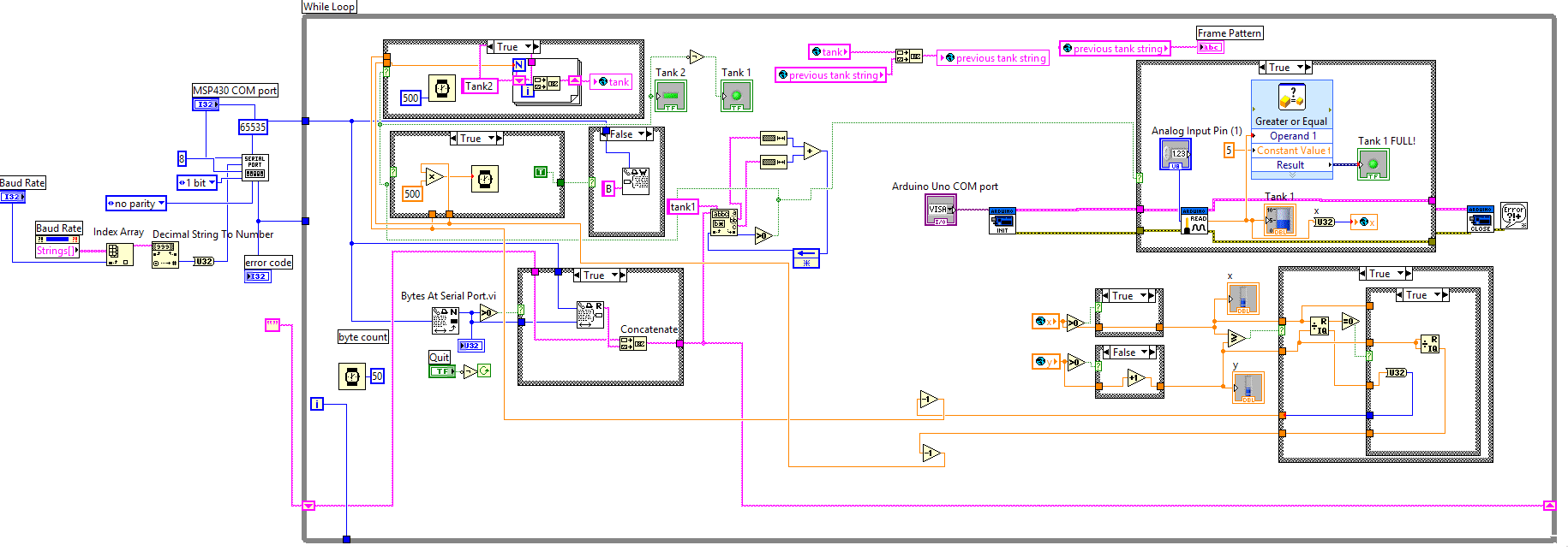
The Back end programing Panel consists of blocks representing equations and I/O lines of the microprocessor. It computes the needed values and takes decision based on it.
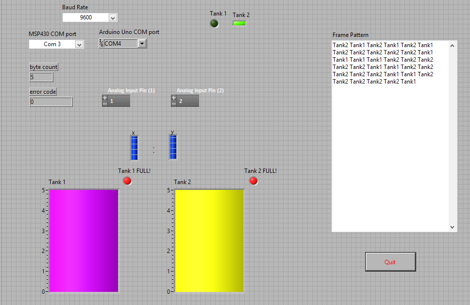
In the Front Panel, the Baud rate for data communication is selected. Analog pins which display the voltage from the pressure sensor fixed to the paint tanks are selected. Calculations are done by the CPU based on these values to fix their priorities and to display the tank level in the front panel. LEDs are used to indicate the shifts in pinging process and also to alert the controller in case the tank is full. The frame format is used to display how the weighed TDMA works. Higher the priority, more the timeslots allocated for reading a tank’s level.
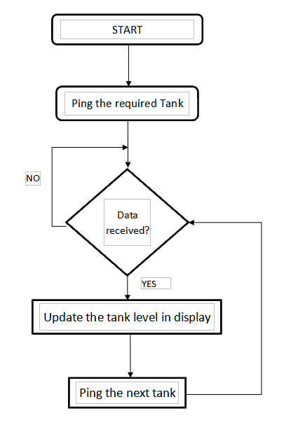
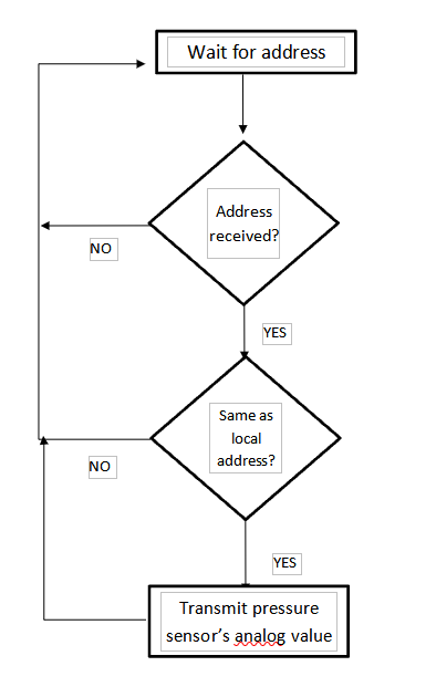
In the Back Panel, blocks represent the coding for the entire process. Basic initialization processes would be the serial port initializations, global variable declaration and fixing of buffer size. The DCS will ping each tank using their address. The authenticated tank will transmit its analog voltage value from the pressure sensor to the DCS. This value is stored in the global variable and buffered till other such values from every tank is achieved. The ratios between the type casted integer values of the analog inputs are found. They are then simplified using mathematical calculations. This helps to set priority to the tanks. Time slots are then divided based on the priority and the process is done all over again once a cycle is completed. The tank levels are updated in the front panel for the controller to view. If in case a tank is full, there is a feature to auto turn off the diaphragm pump. The paint is auto transferred from Mix tank to the Supply tank. When the Supply tank is full, the pump is again turned off and the paint is transferred to the painting robotic arms and to the paint guns. Finally the serial ports are closed and refreshed before receiving the address and analog values from the next cycle of processing.