Repository navigation
Home
This project was initiated to assess the frequency accuracy of a test bench. General principles of the test bench:
- A CPU is updating a simulation model of a plant.
- IO boards are transmitting the state vector of the plant to various control computers under tests.
The CPU is running an OS that is not of hard real-time type. However this OS meets roughly the requirements, except for some short and exceptional situations where some cycles (or OS ticks) may be delayed, or even lost. The purpose was therefore to deploy a tool able to monitor the jitter affecting the OS ticks. When a real time issue is detected in the test results, the monitoring tool is first checked to decide whether the root cause is the test bench jitter, or located in the design of the system under tests.
The following picture depicts the time organisation of the simulation:
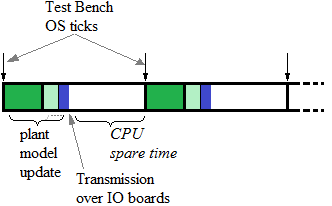
The goal of the Jitter-Meter is to assess the fluctuations affecting the OS ticks period (aka jitter). In this purpose, the bench software is instrumented by adding the transmission of an RS232 NULL character at the very begining of each cycle. The NULL character is made of:
- 1 start bit at "zero" level;
- 8 bits at "zero" level also; and
- 1 stop bit with a "one" level
The RS232 line then keeps on its space state ("one" level at UART output; low voltage on RS232 line). This globally results in a 9-bit pulse width:
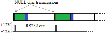
The rising edges of this signal are a materialization of the CPU ticks. The Jitter-Meter associates a time tag to each rising edge and delivers these successive time tags over a COM port to a PC. The time tags are issued from the arduino timer (LSB of 1 µs, resolution of 4µs, 32-bit word width)
The input #2 of the arduino is used, since it is able to trigger an interrupt. The sole issue is to adapt the electrical levels from ±12V (RS232 levels) to the Arduino levels (5V/0V). This is achieved by inserting a 22kΩ resistor in the signal path ... :
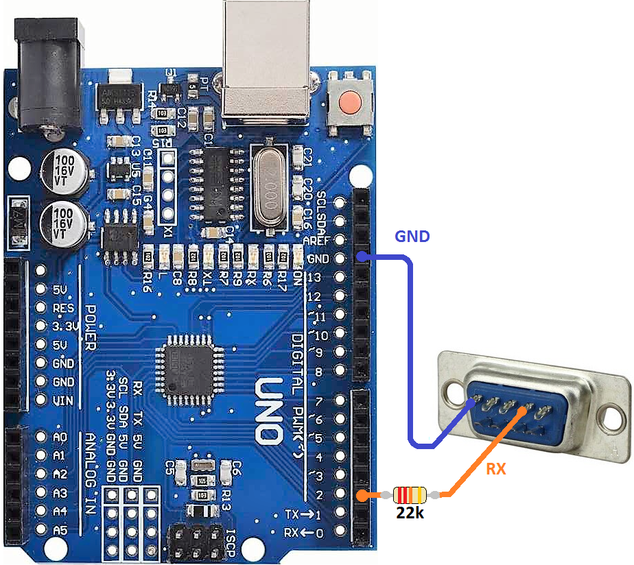
... and the clipping diodes inside the arduino MPU are doing the rest of the job.
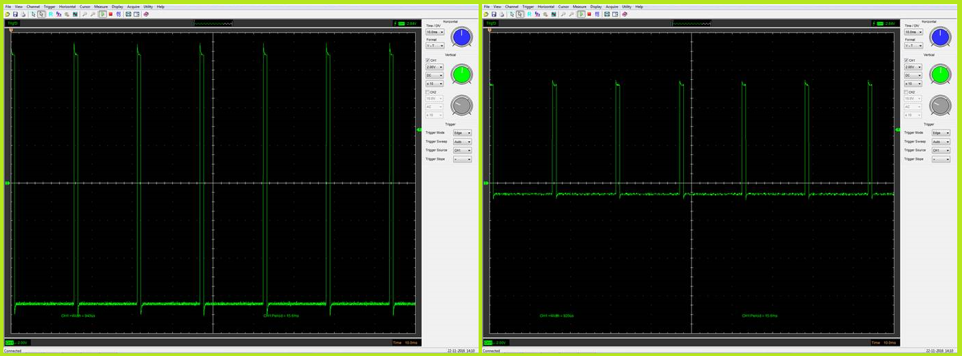
The following oscilloscope snapshots depict the effect of the clipping diodes associated with the series resistor. The left picture corresponds to the RS232 TX signal at the output of the bench CPU board. The right one is the input #2 of the arduino. The vertical scales are the same. It can be noticed that the RS232 voltage swing is only of ±7V rather than ±12V as expected from RS232 standard. This is due to the USB<=>RS232 device that was used to perform the test. In these devices, only a +5V power supply is available. A simple capacitor-based voltage doubler is operated, where a trippler would be required to meet ±12V. But ±7V is enough to comply with the standard:
Beside the initialization phase (setup) where the serial link is opened and where the IO pins are properly configured, all the stuff lays into the ISR (Interrupt Service Routine) associated to the rising edge on input #2 event. This ISR is only made of one instruction:
Serial.println((unsigned long int)micros(), HEX);
It can be noticed that the loop() function also contains some lines of code. These are dedicated to the generation of a self-test signal on pin #13.
See "Testing" page of this wiki