Controllers
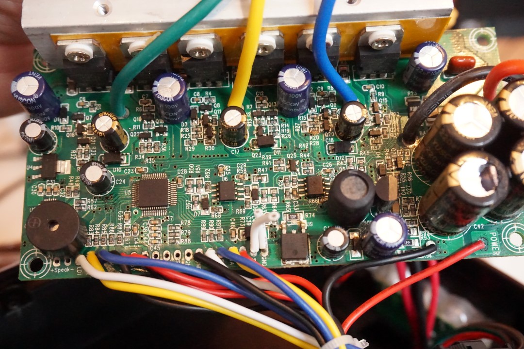
The generic EUC controller electronic board is mainly composed of:
- Microcontroller STM32F103 - is "the brain" of the system
- BLDC controller - include 6 power mosfets and all the circuitry to control them; hall sensors circuit; BEMF circuit; current measurement
- IMU MPU6050 - the accelerometer and gyroscope
- Buzzer
- LEDs - for indicating the battery status
Picture of a EUC controller electronic board:
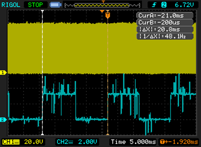
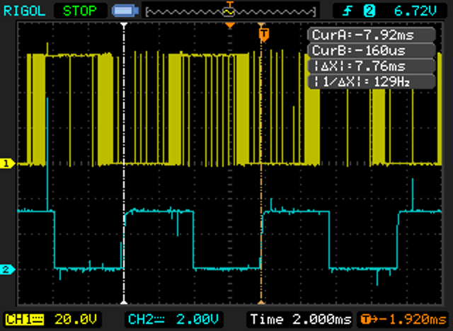
Seems there are 2 different ways to control the motor - one for low speed up to medium speed and other for higher speed. The 1st way seems specific to this application were a motor may work at very low speeds and even stopped. The 2nd way seems to be the standard 6 steps trapezoidal control.
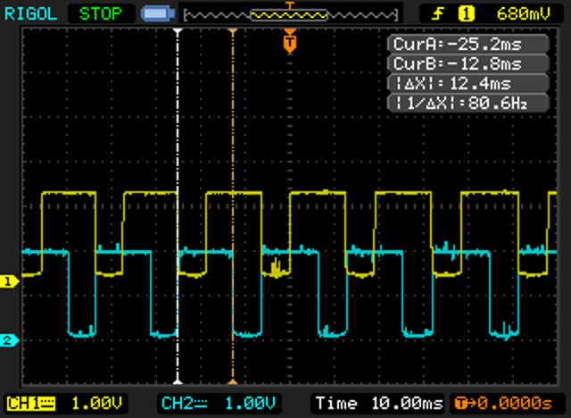
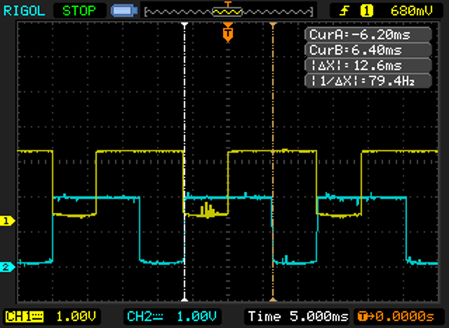
1st way, low to medium speed: yellow: phase 1, blue: hall sensor signal.
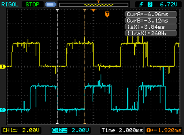
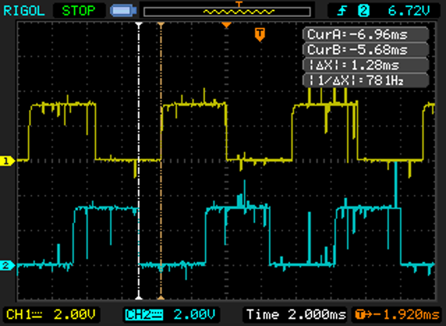
2nd way, high speed: yellow: phase 1, blue: hall sensor signal.
On the 1st way, when the wheel is stopped, there is a square (duty-cycle is 50%) on all the 3 phases (the signals are in phase) and the frequency is 15.625khz.
Yellow: phase 1, blue: phase 2. Motor stopped:
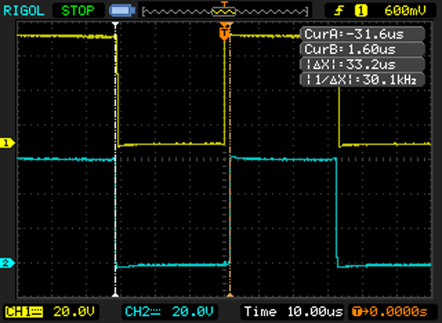
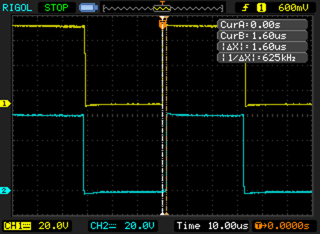
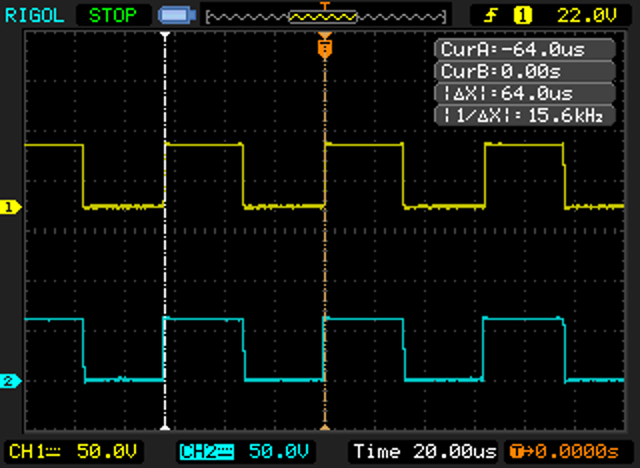
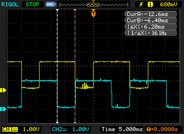
The motor rotates to left if duty-cycle lower than 50% and rotates to right if is higher.
Yellow: phase 1, blue: phase 2. Wheel rotating left:
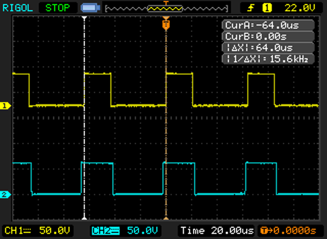
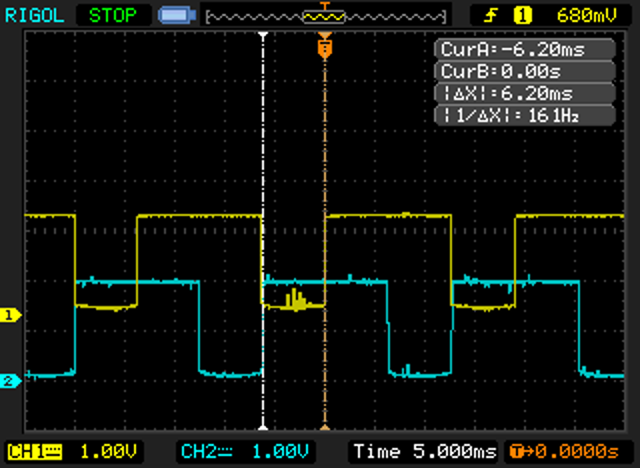
Yellow: phase 1, blue: phase 2. Wheel rotating right:

Yellow: hall sensor 1, blue: hall sensor 2 (signals before the low pass hardware filter):
Yellow: phase 1, blue: BEMF signal 1:
Please see MicroWorks 18m/h controller board page were we are documenting the technical details.
See more picture here: https://github.com/generic-electric-unicycle/documentation/tree/master/images/controller