Reference Designs
There are many different ways to integrate the SpoolScale with your 3D printer. Below are a number of examples and reference designs, showing possible ways to implement the SpoolScale. You can either copy these directly or draw inspiration from them for your own design.
If you make & post your own design for the SpoolScale, send me a message and I can include it here!
Jump to:
The design for the Artillery Sidewinder X1 re-uses the printer's stock sheet metal spool holders, and adds a load cell on a 3D printed mount underneath each one. The SpoolScale is then mounted on a 3rd, separate 3D-printed mount.
Note: This design does not work with spools thinner than ~60mm.
Step 1: Load Cell Mounts
First, we will assemble the 2 load cell mounts. Each of these will need:
- 1x Load Cell Mount
- 1x Spool Mount Adapter
- 2x Load Cell Spacer
- 4x M4x12 Countersink Screws
- 2x Load Cells
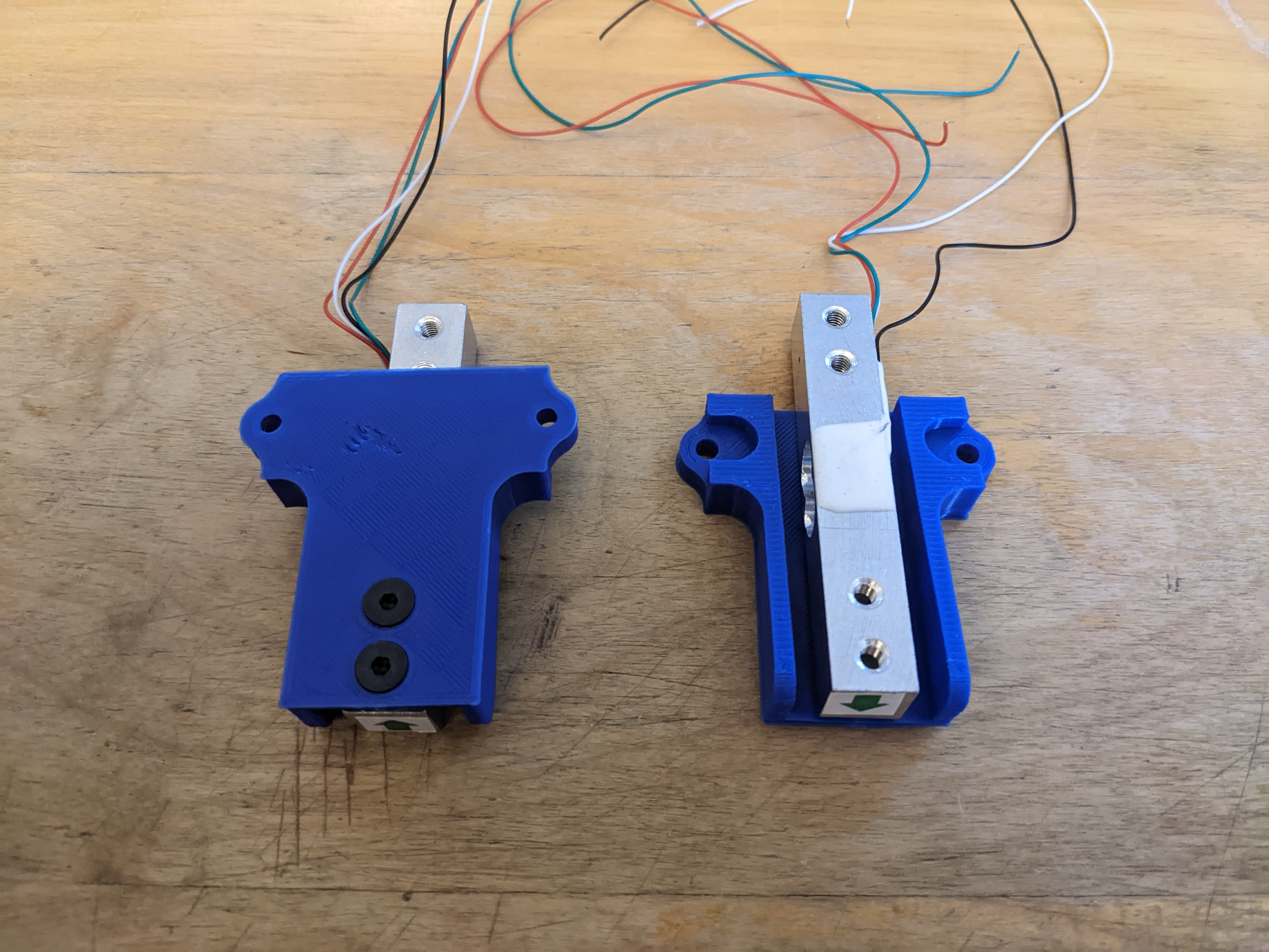
To assemble the mounts, start by putting 2 of the M4x12 bolts through the bottom of the Load Cell Mount. Next, slide a Load Cell Spacer over the 2 bolts. Now, use these 2 bolts to secure the side of the load cell that doesn't have the wires on it. You want to orient the load cell so that the sticker with the arrow on it points down, toward the solid bottom of the Load Cell Mount. Try to center the load cell between the two walls of the Load Cell Mount. You also want to check and make sure that the load cell is not contacting anything except the Load Cell Spacer. Rarely, some load cells will have more epoxy on them that contacts the Load Cell Mount. If this is the case, add another Load Cell Spacer underneath. When complete, it should look like this:
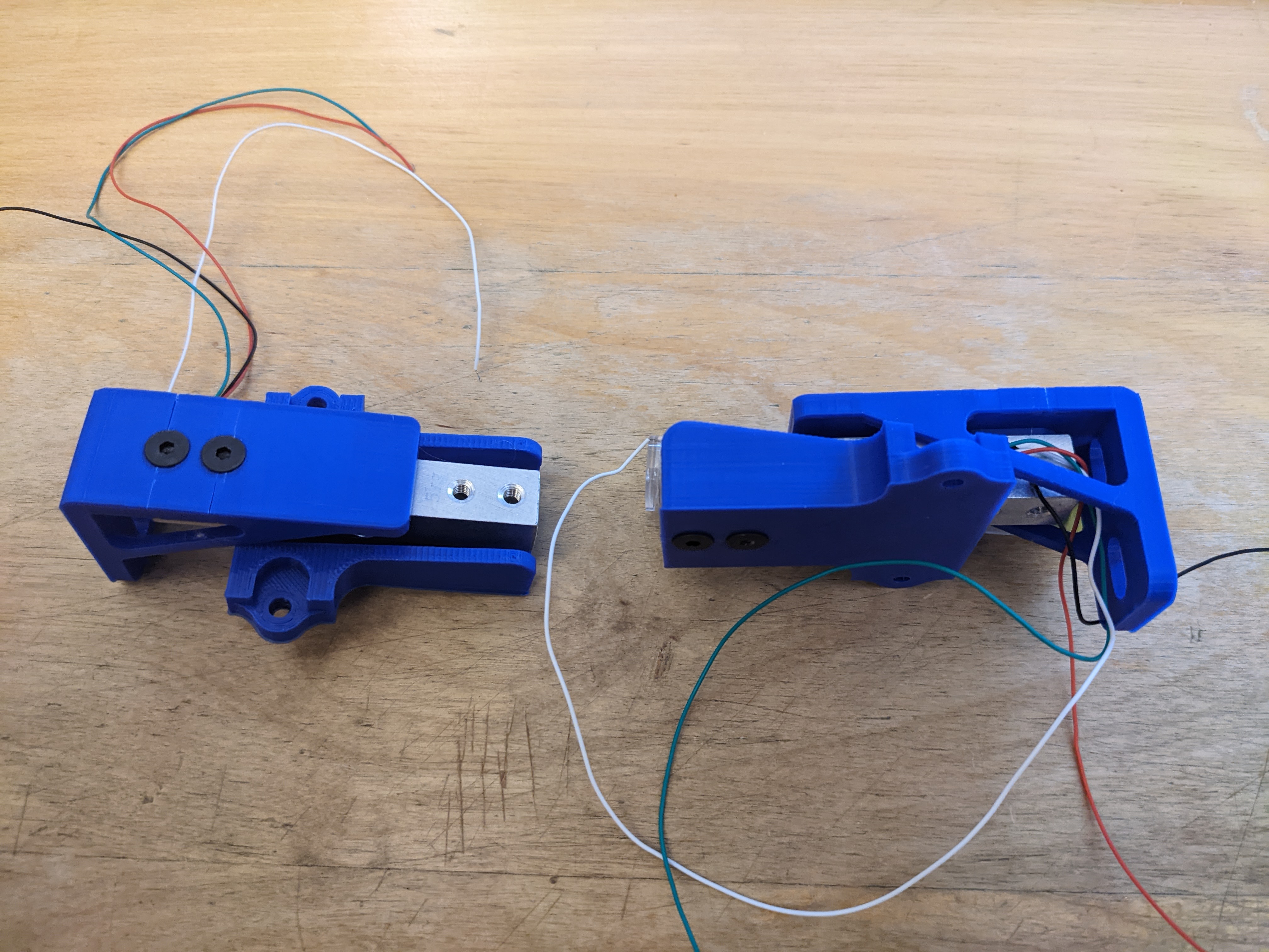
Next, we will mount the Spool Mount Adapter to the other side of the load cell. Put the other 2 M4x12 countersunk bolts through the Spool Mount Adapter, and put a Load Cell Spacer on them. Align the Spool Mount Adapter over the top of the load cell, with the flat side of the Spool Mount Adapter hanging off the back, as seen below. If these screws are overtightened and the Spool Mount Adapter was printed in the wrong orientation, there is a chance of the printed parts cracking, as seen below.
Repeat these steps to complete 2 separate load cell assemblies.
Step 2: Spool Holder Mounting
The stock Artillery Sidewinder spool holders can now be attached. To attach them, you will need the following parts:
- 4x M5x18mm Countersink Bolts
- 4x M5 Nut
- The original Sidewinder Spool Holders
- 2x Spool Spacer
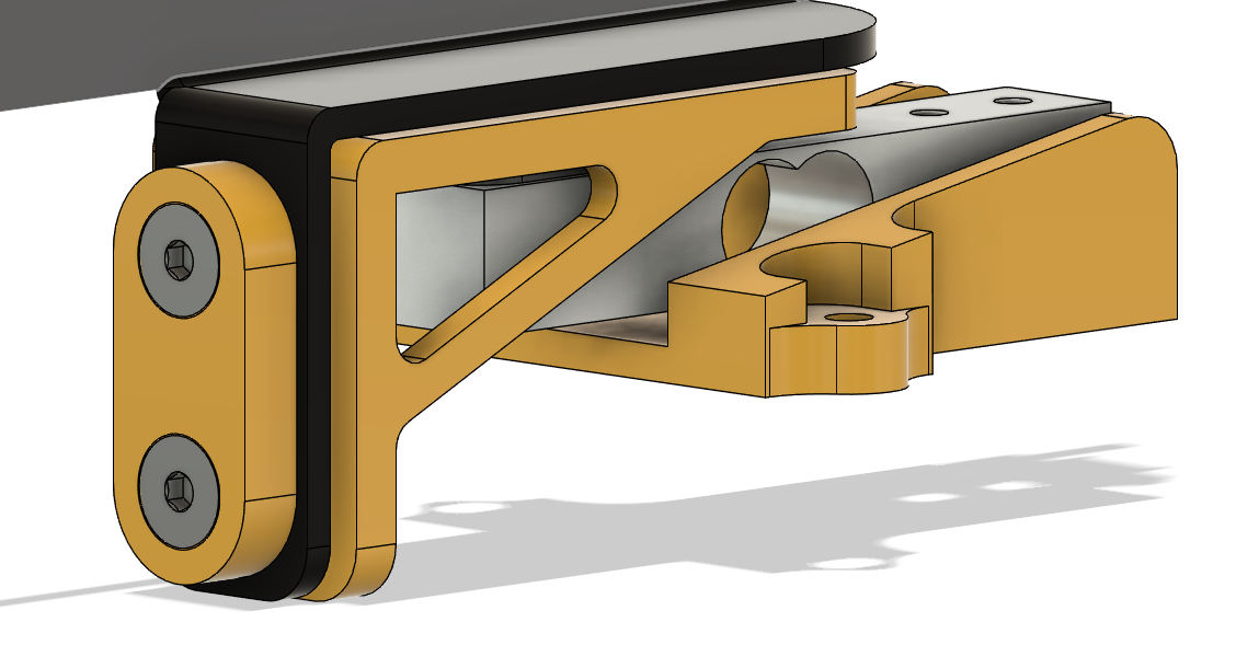
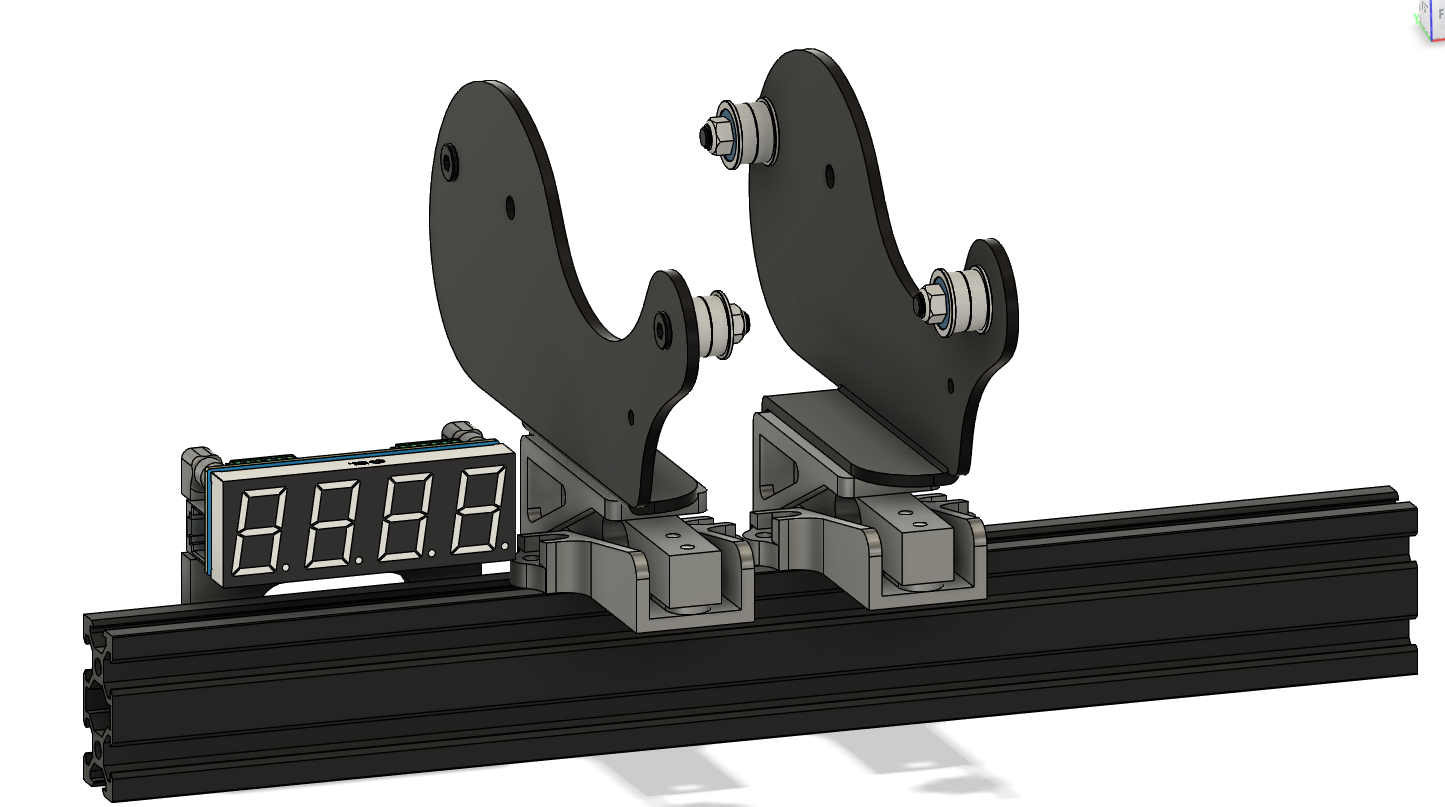
Each of the spool holders is secured to a Spool Mount Adapter from the previous step, as shown in the render below. The M5x18 countersunk bolts go through the Spool spacer, through the original spool holders, through the Spool Mount Adapter, and then into an M5 nut on the back. One of the Sidewinder spool holders will have the stock filament runout detector on it. This can be unplugged and removed, as it can interfere with the SpoolScale's ability to get an accurate measurement.
Step 3: SpoolScale Mount
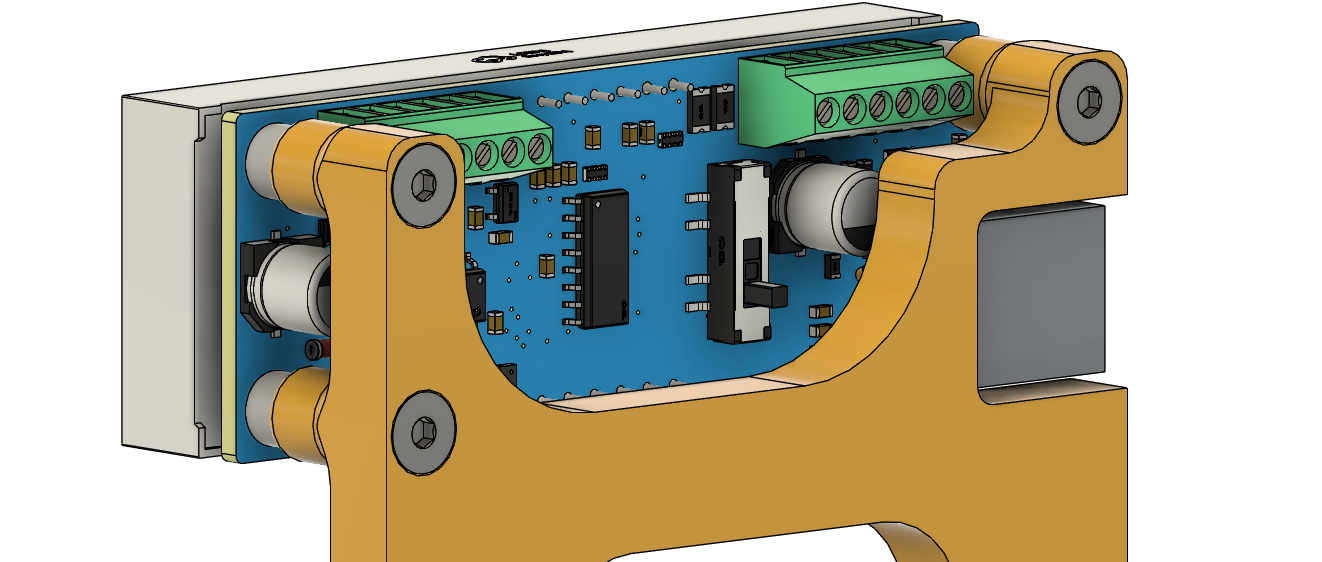
Now, we can mount the SpoolScale controller to its 3D-printed mount. This is done with 3 M3x16 countersunk bolts. Align the SpoolScale's 3 threaded mounting holes with the 3 holes in the Interface Mount, as shown below.
Step 4: Printer Mounting
First, we will mount the SpoolScale to the 3D printer. To do this, put two M5x12 countersunk bolts through the 2 bottom holes in the Interface Mount. These can then be secured into the original M5 nuts that are in the aluminum extrusion from the stock spool holders. There are 2 more countersunk holes for 2 more bolts if needed, but in testing, just the bottom 2 was more than enough to secure it to the machine. The SpoolScale should be mounted on the left side of the 3D printer, leave it fairly loose for now until you've mounted the spool holders again. Then you can move the SpoolScale in to be no more than an inch or two from the spool holders.
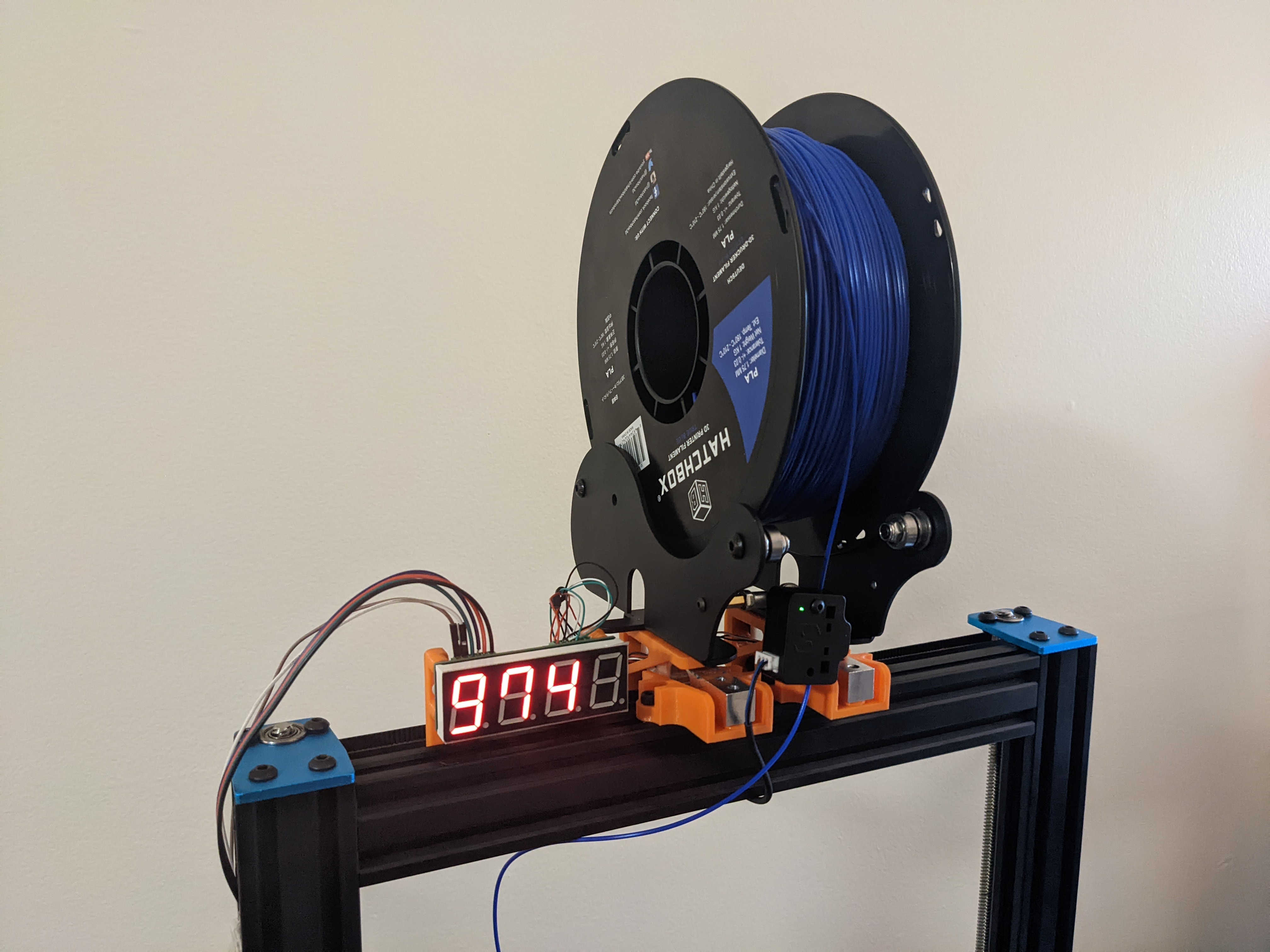
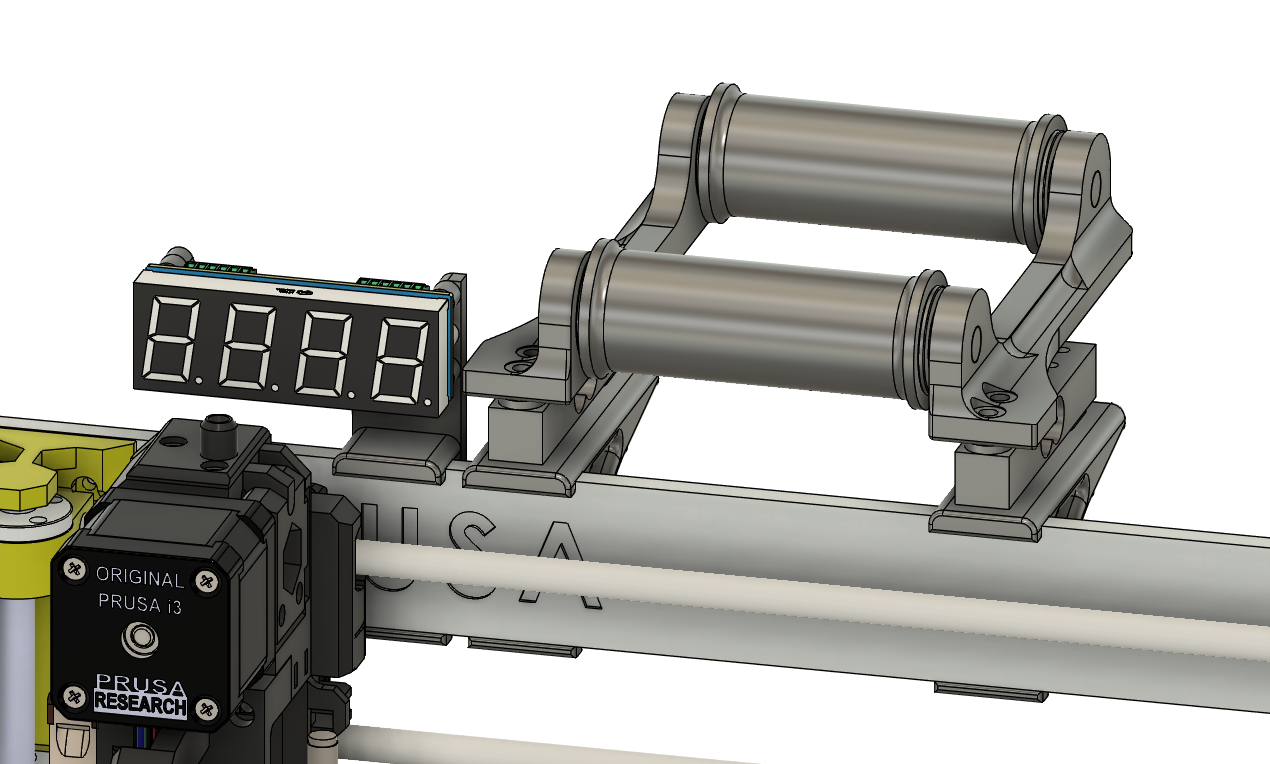
Next, mount the spool holders. This is done with two M4x12 socket head screws and two M4 T nuts for each Load Cell Mount. Mount these to the top extrusion of the 3D printer, roughly centered. The exact spacing between them depends on what style of spool you're printing with, but for most spools you can mount them so at the edges of the two Load Cell Mounts are directly touching. See the "Photos" section below for an example of the entire system mounted to the 3D printer.
Step 5: Wiring
Before doing any wiring, turn off and unplug the 3D printer from the main power and any attached computers/devices. Turn on the power switch for at least 30 seconds after this to fully discharge any capacitors!
For more detailed information on wiring the SpoolScale, see the User Manual section on wiring.
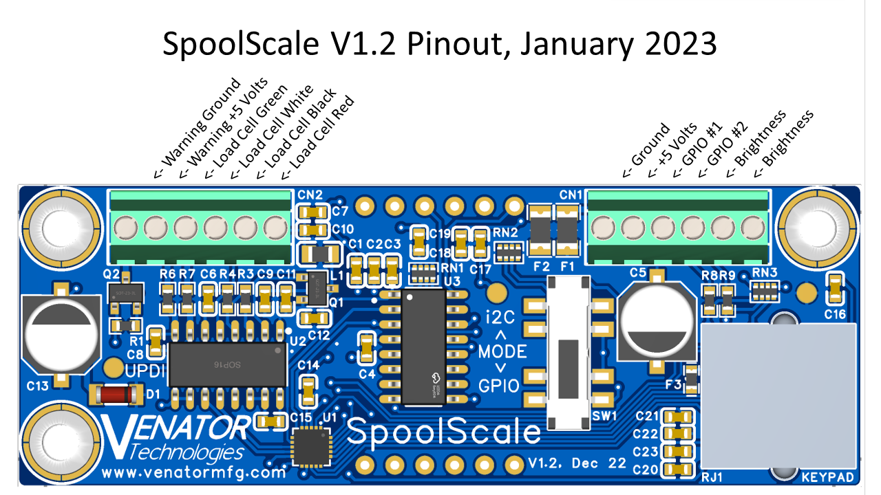
We will start with the wiring of the load cells to the Spool Scale. To do this, route the wires from the load cells underneath each load cell, zip-tieing them such that they do not contact the Z-axis timing belt. Then route it up to the top of the SpoolScale. The two load cells will be wired in parallel (i.e. both the green wires into the same terminal, both the reed wires into the same terminal, etc.), as seen in the wiring diagram below.
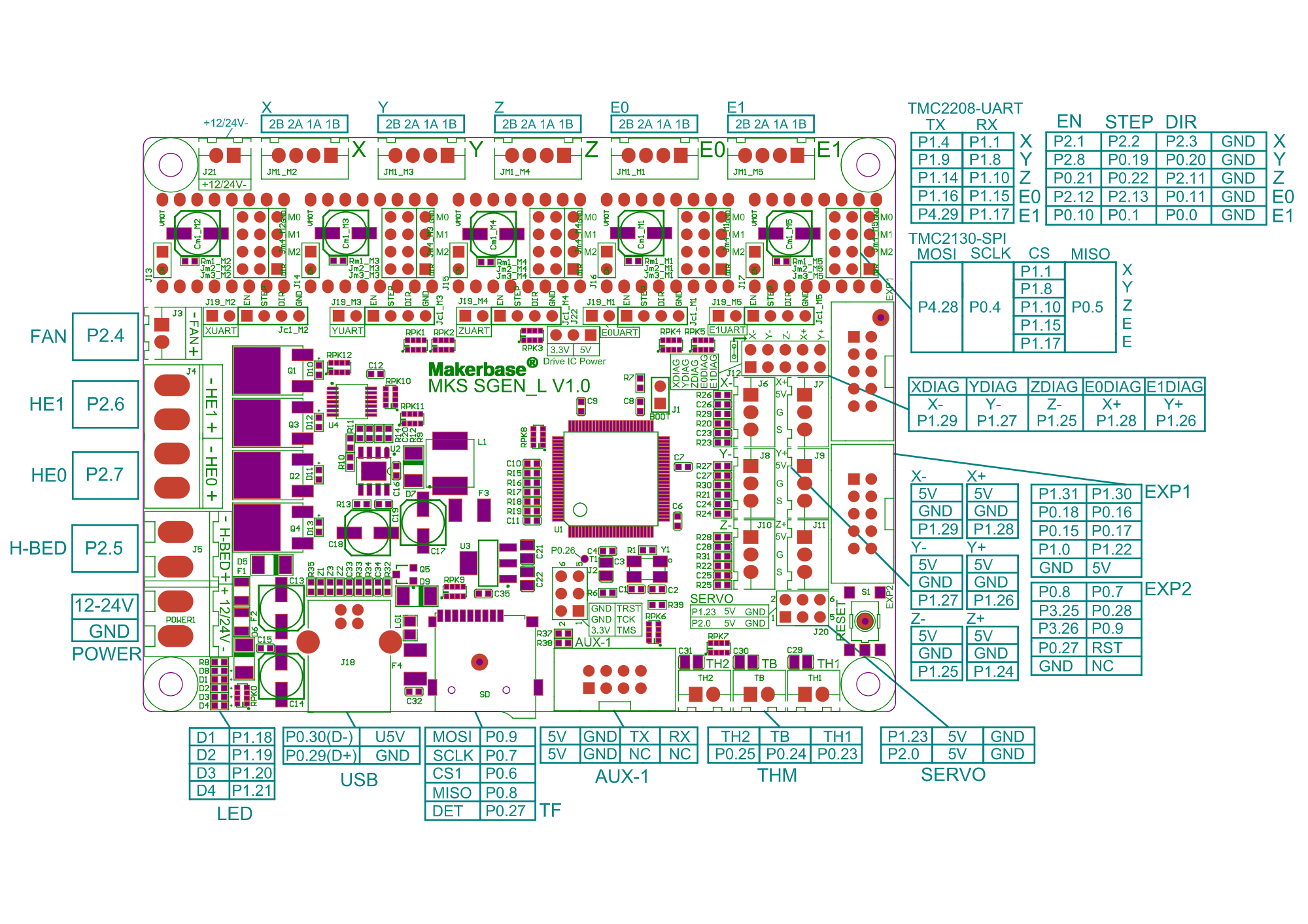
Next, we will connect the wiring for the 3D printer. Start by connecting 4 wires (3 are needed, and the 4th is for future-proofing) to the SpoolScale for +5 Volts, Ground, GPIO #1, and GPIO #2, as seen in the wiring diagram below. Route these wires down the back of the aluminum extrusion for the Z axis, tucking them into one of the recesses. Once you reach the base of the 3D printer, push them through the hole for the Z-axis stepper motor's wiring. Now that the wires are inside the base of the printer, open the bottom and route them with the rest of the wires to the control board. Make sure to zip-tie the wires securely, so that they do not contact the fan or other internals of the electronics area. While any IO and power/ground pins can be used for the SpoolScale, the easiest to access are the bottom 4 pins of the large connector "EXP1", found on the right side of the control board (opposite from the screw terminals for the heaters and main power). If the board is oriented so that EXP1 is on the right, the bottom right pin will be +5 volts, the one next to it will be ground, and the 2 above it will be IO you can use for the SPoolScale. See the MKS Gen L V1.0 pinout below for more details. Make sure to re-install the bottom panel of the machine exactly how it was originally once done.
If you have attached the SpoolScale as listed above, the screen should turn on when you power on the printer. You can then send the following G-Code commands to the printer (assuming you wired it exactly as listed above):
M42 P27 S0 T1 should turn off the SpoolScale
M42 P27 S255 T1 should turn on the SpoolScale
It is recommended to input these to the start and end g-code of your slicer respectively, so that the SpoolScale is turned off while printing. For more information, see the User Manual section on GPIO toggles.
Direct Link to Files (GitHub)
Direct Link to Files (Printables)
Direct Link to Files (GitHub)
Direct Link to Files (GitHub)
Direct Link to Files (VORON Mods)
