User Manual
This is the primary user's manual for the SpoolScale. The contents of this manual are written specifically for use with hardware version V1.2, running software version V1.2.1.
Click to show pinout
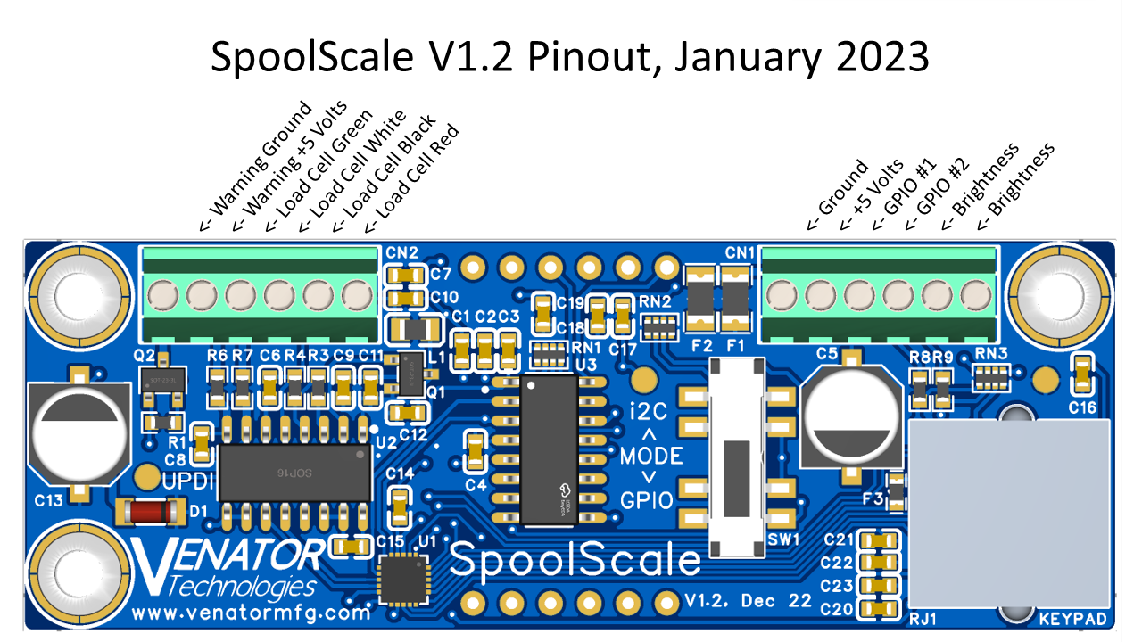
When wiring the SpoolScale, it is recommended to use 22 gauge or larger stranded wire where possible. Try to reduce the amount of exposed copper wire outside of each screw terminal, to minimize the risk of short-circuits.
The SpoolScale runs on 5 volts, and all inputs/outputs are at 5-volt logic levels. Do not connect the SpoolScale directly to any system that does not have 5-volt compatible logic input/outputs! If interfacing the SpoolScale with a 3D printer's electronics, the two systems must share a ground connection (although power for the SpoolScale can optionally be supplied by an external supply). The SpoolScale draws at most 250 milliamps while operating, nominally being around 100mA. With the screen dimmed/off, this drops to below 20mA.
The power input has 2 self-healing polymer fuses on it, both rated for a minimum hold current of 1 amp and a maximum trip current of 1.8 amps. One of these is for the internal circuitry of the SpoolScale, and the other is for the warning output. The input is also protected by a Zener diode with a nominal voltage of 5.6 volts, to reduce damage from accidental overvoltage.
The SpoolScale is designed to work with Wheatstone Bridge load cells. The specific rating and number of load cells needed depend on the 3D printer and spool being used. If a setup uses multiple load cells, they can be wired in parallel, i.e. connect the red wires together, connect the black wires together, etc. If multiple load cells are used, they must all be of the same rating and as close to physically identical as possible.
The pinout above names the load cell terminals with their most common colors; Excitation Positive being red, Excitation Negative being black, Signal Negative being white, and Signal Positive being green. Reference the specific datasheet for your load cells for which wires are which. Load cells included with the SpoolScale will follow the correct wire coloring.
There is a warning connector on the far side of the SpoolScale's screw terminal that can be used to trigger an external device when/if the filament remaining drops below 50 grams. If this happens, the terminal labeled "Warning Ground" will switch from high impedance to ground. This can be used to connect to a microcontroller, an LED, a buzzer, etc. to indicate the printer is low on filament. This output is only active when the SpoolScale is in its active state and defaults to high impedance when the SpoolScale is in idle mode.
For the convenience of wiring this output to an LED or buzzer, the screw terminal adjacent to it is a 5-volt output, drawn directly from the 5-volt input of the SpoolScale.
The brightness of the SpoolScale's display can be adjusted to one of 8 intensity levels using the two terminals labeled "Brightness". The SpoolScale will default to full brightness if these pins are left disconnected or shorted together. Other brightness settings can be achieved by putting a resistive device between these two terminals. Statis brightnesses can be set with resistors, or a photoresistor or potentiometer can be used to vary the brightness. The following table details the nominal resistance for each brightness step:
| Range | Nominal | Brightness |
|---|---|---|
| 10k to 20k | 15k | 0 (Off) |
| 1k to 2.3k | 1.6k | 1 |
| 2.3k to 3.6k | 3k | 2 |
| 3.6k to 5k | 4.3k | 3 |
| 5k to 6.3k | 5.6k | 4 |
| 6.3k to 7.6k | 6.8k | 5 |
| 7.6k to 9k | 8.2k | 6 |
| <1k, >20k | No Connect | 7 (Max) |
It should be noted that these brightness steps are what the internal circuitry uses, and do not linearly correlate to what the human eye can see. So steps towards the bottom of the scale will seem much more drastic than those towards the top.
The SpoolScale has two terminals, referred to as GPIO #1 and GPIO #2 respectively, that are intended for interfacing with 3D printers.
If operating the SpoolScale independent of a 3D printer, these can be left disconnected and the SpoolScale will always be on.
If the SpoolScale is connected to a 3D printer's I/O and an M42 or similar G-code command is being used to change it from active to idle mode, either (or both) of the GPIO terminals can be used. If either one is pulled to ground, the SpoolScale will enter idle mode. When pulled high or disconnected (each pin has an internal 10k pullup), the SpoolScale will return to active mode.
If the SpoolScale is connected to a USB-UART adapter for configuration, GPIO #1 is the RX, and GPIO #2 is the TX.
If the SpoolScale is connected as an i2C slave device, GPIO #1 is SCL, and GPIO #2 is SDA. Both of these are internally pulled up with a 10k resistor.
It is necessary to configure the SpoolScale before use. There are two different ways to do this; with a USB-Serial adapter, or with an i2C keypad. The i2C keypad is the suggested way of configuring the SpoolScale as it is much more convenient and unlocks more functionality.
Mode Configuration
The first thing to configure is the mode of operation. This can only be done when the SpoolScale is powered off. The mode of operation is selected using a switch on the back of the Spool Scale. If switched down, the SpoolScale will enter GPIO mode upon startup. If switched up, the SpoolScale will enter i2C mode upon startup. If the switch is left in the center, the SpoolScale will enter UART configuration mode upon startup.
Configuration with Keypad
Note: Configuration with keypad only works if the SpoolScale is in GPIO mode.
First, connect the keypad to your SpoolScale using the included RJ12 cable. It is recommended to connect the keypad to the SpoolScale while it is powered off, but plugging the keypad into an already-powered-on SpoolScale usually works. It is important to note that the keypad inputs are ignored if the SpoolScale has been disabled by the printer's GPIO, so you can only configure settings when the SpoolScale is on and in active mode (when the screen is displaying the weight).
To prevent accidental changing of settings, the first keypress of any settings change has to be held down for 2 seconds. After that, keys can be pressed at any speed. Keep in mind the keypad can only process hitting a single key at a time, so make sure to fully release one key before pressing the next.
The following keys can be pressed to modify a setting:
A-D: Pressing and holding one of these 4 keys will load a saved spool weight. When successfully loaded, the screen will display the letter (as best it can, being a 7-segment display) followed by the weight for a second before returning to normal operation.
#: Pressing and holding the pound (aka "hashtag") button on the keypad enters the spool weight setting mode. The screen will display "____" when successfully entered. You can then use the numbers to enter a spool weight, between 0 and 999 grams. Pressing # again will save that as the current spool weight, or pressing one of the A-D keys will save that number as the respective preset. Saving the weight as a preset does not automatically call that preset, you would have to do that by pressing and holding the key.
*: Pressing and holding the asterisk (aka "star") button on the keypad will enter calibration mode. Follow the on-screen prompts and reference the section of the User Manual about Calibration for more information. When using the keypad, pressing any key will advance to the next step of the calibration.
Configuration with USB
To configure over USB, connect any USB-UART adapter of your choice to the SpoolScale's two GPIO screw terminals while the system is powered down. The one closer to the +5 volt input is the RX pin, so it should be connected to the TX pin of the adapter. The other GPIO is the TX pin, so it should be connected to the RX pin of the adapter. You will also have to connect +5 volts and ground from the USB-UART adapter to the SpoolScale's power and ground screw terminals. Nothing else should be connected to the power and GPIO pins while using a USB-UART adapter, so the configuration of your SpoolScale through this method does mean essentially uninstalling it from your 3D printer to make changes.
Before plugging in the USB-UART adapter, slide the mode selector switch on the back of the SpoolScale to the center position. Then, plus in the adapter and connect to it with the serial terminal of your choice at a baud rate of 9600. Once the SpoolScale receives power, you should see the display on the front read out "Uart" to show it is in UART configuration mode.
There are only 4 UART commands supported for configuration. All commands are case-sensitive:
s XXX sets the empty spool offset weight to XXX grams. Positive values between 0 and 999 grams are accepted. Sending this command immediately saves the new value to EEPROM.
c will start the calibration routine, spitting out commands over UART. When prompted, you will have to send subsequent "c" characters to move on to the next step.
w will report the current weight of the remaining filament, in grams.
h will list out help and information.
You can simply remove power from the SpoolScale when you are done configuring it this way, and then re-wire it to return to normal operation.
Configuration with i2C
If running in i2C mode, it is possible to configure the SpoolScale directly with the i2C connection. See the section on Interfacing via i2C for more information.
Load cells are incredibly sensitive devices. Minute changes in input voltage, the temperature/humidity of the room, and even the heat generated by current flowing through the load cells will all impact the reading. Therefore, it is important to regularly calibrate the SpoolScale. Exactly how often it needs to be done will depend on a lot of factors, but in general, it is recommended to do a manual calibration at least weekly, and allow the automatic calibration to run regularly.
Automatic Calibration
The automatic calibration, as the name implies, occurs automatically. There are two types of automatic calibrations that occur; power-up, and time-interval. Time-interval automatic calibration occurs roughly every hour the SpoolScale is not in idle mode. At the start of the hour, the SpoolScale will note how much filament it thinks is on the spool. Then, over the next hour, it'll track how far the current measurement gets from that reference value. If it deviates by more than 10 grams (for example, if you swapped out spools, bumped into the printer, started a print without putting the SpoolScale into idle mode, etc.), it will restart the automatic calibration. If there has been a notable but slight change, the SpoolScale assumes this was caused by drifting over time, and the system will automatically adjust its calibrations to try and return to the original value. The second variant of the automatic calibration, power-up, operates the same way. The key difference is that this occurs by comparing the last known value before losing power to the most recent value once power is restored. Therefore, it is important that the same spool/weight is kept on the printer while it is powered off so that the SpoolScale can more accurately re-establish a baseline. Only change out spools while the SpoolScale is powered on! If you do remove the spool while the machine is off, you should run a manual calibration once power is restored.
Manual Calibration>
Manual calibration should be performed at a minimum weekly. Manually calibrating more often will make the SpoolScale more accurate, so some users will do it daily and/or every time they swap spools. The exact way to start a manual calibration depends on how you configure your settings, see the Configuration Chapter of the User Manual for more information. Before beginning manual calibration, configure an empty spool weight that matches something you have on hand. An actual empty filament spool works best for this, but in a pinch, an object of known weight will work, so long as it is roughly the same weight as the spool of filament you'd load onto the printer. For setups that use multiple load cells, it is important that the weighted object loads the load cells equally as if it was a real spool.
Once you enter the calibration mode, the first step, zero-offset, will begin. In this step, the SpoolScale measures how much nothing weighs, or more accurately, how much the spool holder and other miscellaneous stuff on top of the load cells weigh. For this step, make sure that there is nothing on the spool holders that wouldn't be there during normal operation. Once set, continue to the next step.
When the SpoolScale finishes zero-offset, it'll prompt you to load an empty spool for the next step, known-weight calibration. The load cells output a voltage that correlates to weight, but the SpoolScale doesn't know the conversion of how many grams per volt. By putting a known weight on the load cells, the SpoolScale can work out the conversion factor automatically. Once the object of known weight is on the spool holder, continue. The SpoolScale will begin calculating the conversion factor. This may take no time at all, or may take up to 1 minute. During this time, values will be output on the display. Keep an eye on these values, if you see the SpoolScale start to fall into a loop (e.g. it shows -203, then 1056, then 187, then -203, then 1056, then etc.), this means that the SpoolScale may have gotten stuck in the calibration sequence and cannot figure its way out. If this happens, it is usually best to restart the manual calibration sequence, after checking all the wiring for the load cells and the empty spool offset weight.
Assuming the known-weight calibration completes, the display will report "donE", then flash up the current non-offset weight for a few seconds (in other words, the weight of the known object you put on there). The SpoolScale will then return to regular operation, indicated by the display now showing 0.
Interfacing via GPIO
Interfacing via GPIO is the most common operating mode for the SpoolScale, allowing it to interface with nearly any 3D printer, or to run on its own.
