6. Virtual Implementation
Base of card dealer

Circular base

Body of the machine

Circular Pin

Card Holder

Base of the card dealer

Circular Base

Body of the machine

Circular pin

Card holder

Internal spur Gear

Spur Gear

Sub-System 1:

Sub-System 2:

Sub-System 3:

Overall Circuit of the model:


Sub-System 1:

Sub-System 2:

Sub-System 3:

| Sl. No. | Part Name / drawing | Specification | Qty |
|---|---|---|---|
| Sub-system 1 | |||
| 1 | IR Sensor | Range from 2 to 25 cm | 1 |
| Sub -System 2 | |||
| 1 | Beeper | 1 | |
| 2 | LCD Display | 1 | |
| 3 | LED panel indicator | 1 | |
| Sub-System 3 | |||
| 1 | Keypad display | 1 | |
| 2 | DC Helical Geared Motor | 1 | |
| 3 | LED lights | 2 | |
| Common to all | |||
| 1 | Stepper Motor | NEMA17 4.8 kg-cm | 1 |
| 2 | Arduino board | Mega 2560 | 1 |
| 3 | Jumper Wire M\F | 20 | |
| 4 | Speaker | 1 | |
| 5 | LED Lights | 2 |
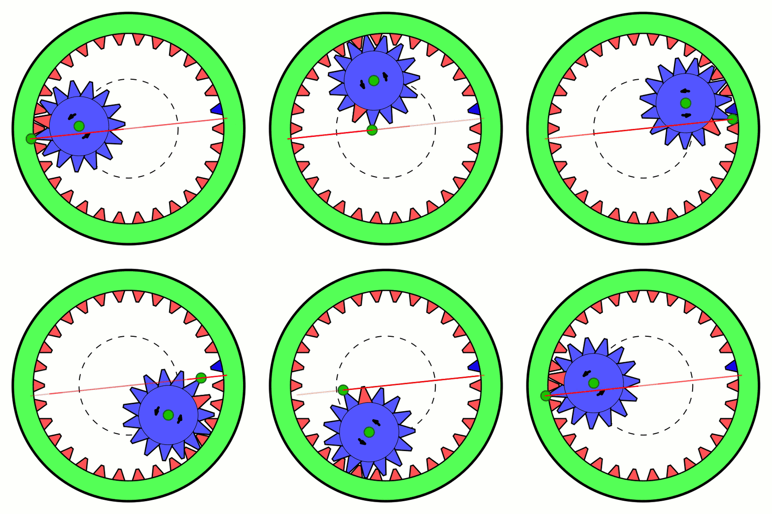
Internal Gear Mechanism for the base stepper motor[1]
References:
[1] MichaelFrey, CC BY-SA 3.0 https://creativecommons.org/licenses/by-sa/3.0, via Wikimedia Commons
