ESP32 firmware for a garden valve controller. Drives 1–8 solenoid valves, talks MQTT and plain HTTP, integrates with Home Assistant. Everything is configured through a web UI on the device. WiFi, MQTT, GPIO pins, all of it. No cloud, no account, 100% local.
A well-tested IoT project without using ESPHome with the intention to keep my garden alive :-).
- No cloud, no account, no phoning home. MQTT to your own broker, HTTP or a WebUI, that's it.
- Plug the device in, log into its AP, visit
http://192.168.4.1to configure initial wifi and gpio pins, and you're good to go!
Use it, fork it, ask me questions, propose a PR, and see Safety notes before you wire up 12V solenoids.
Valves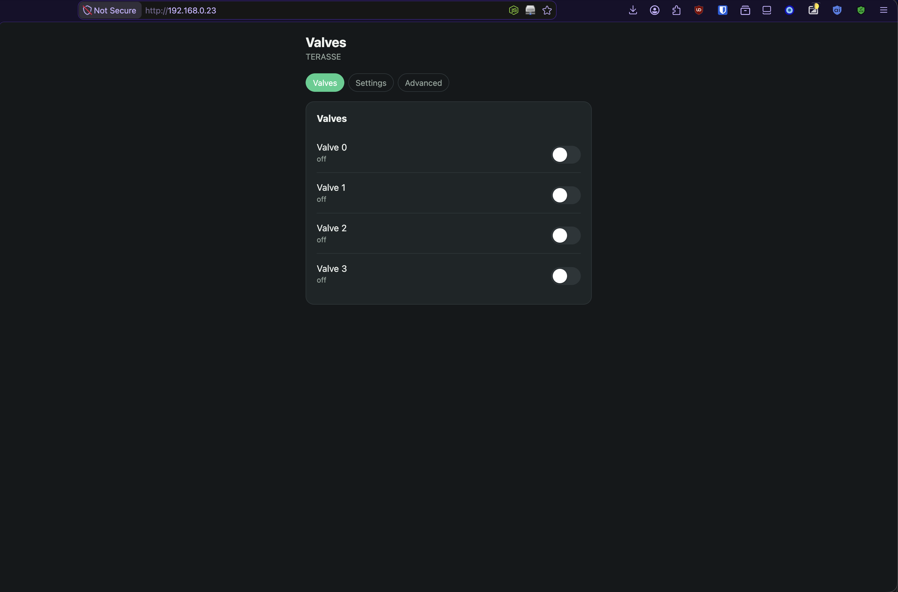 |
Settings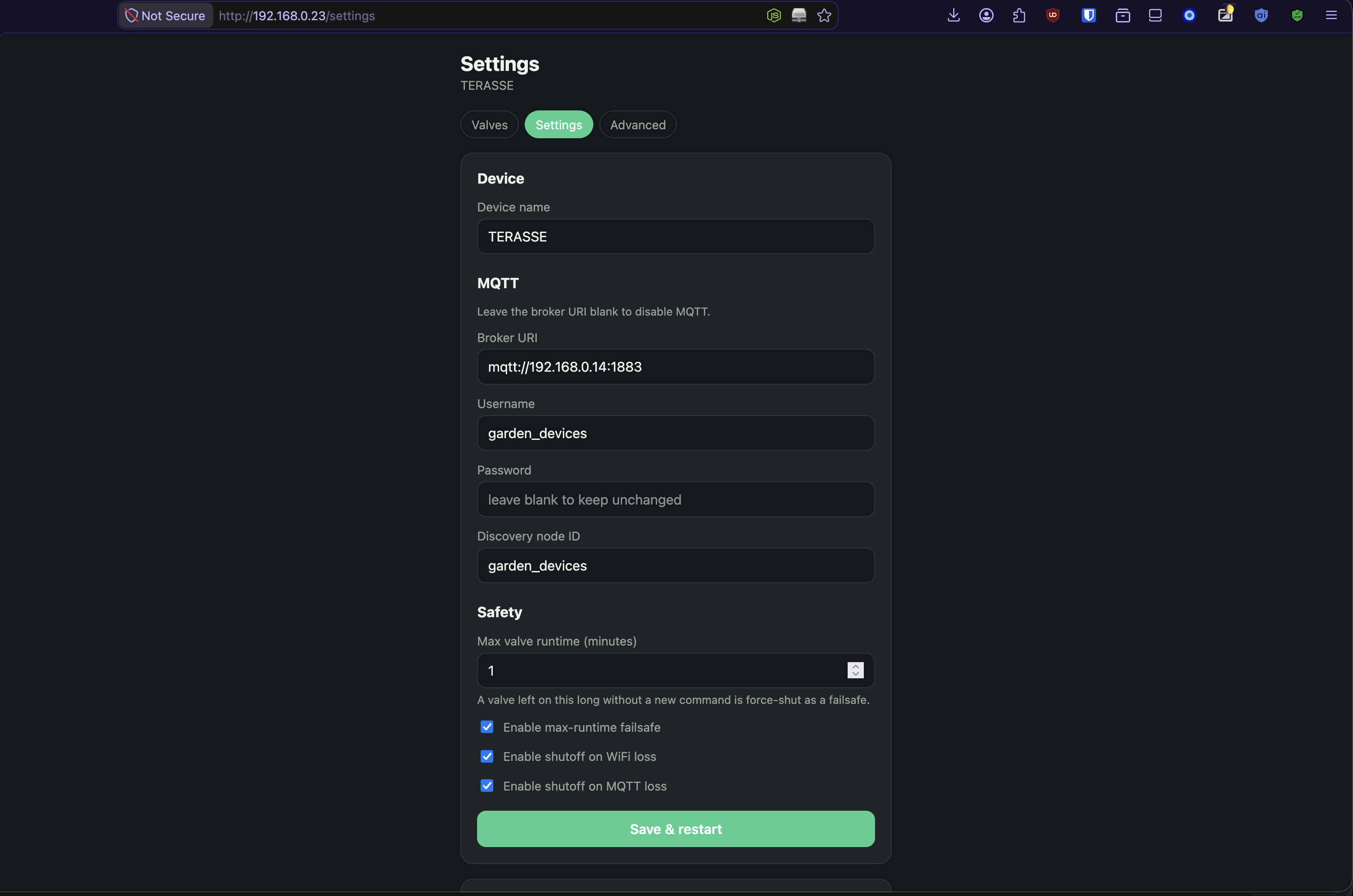 |
Advanced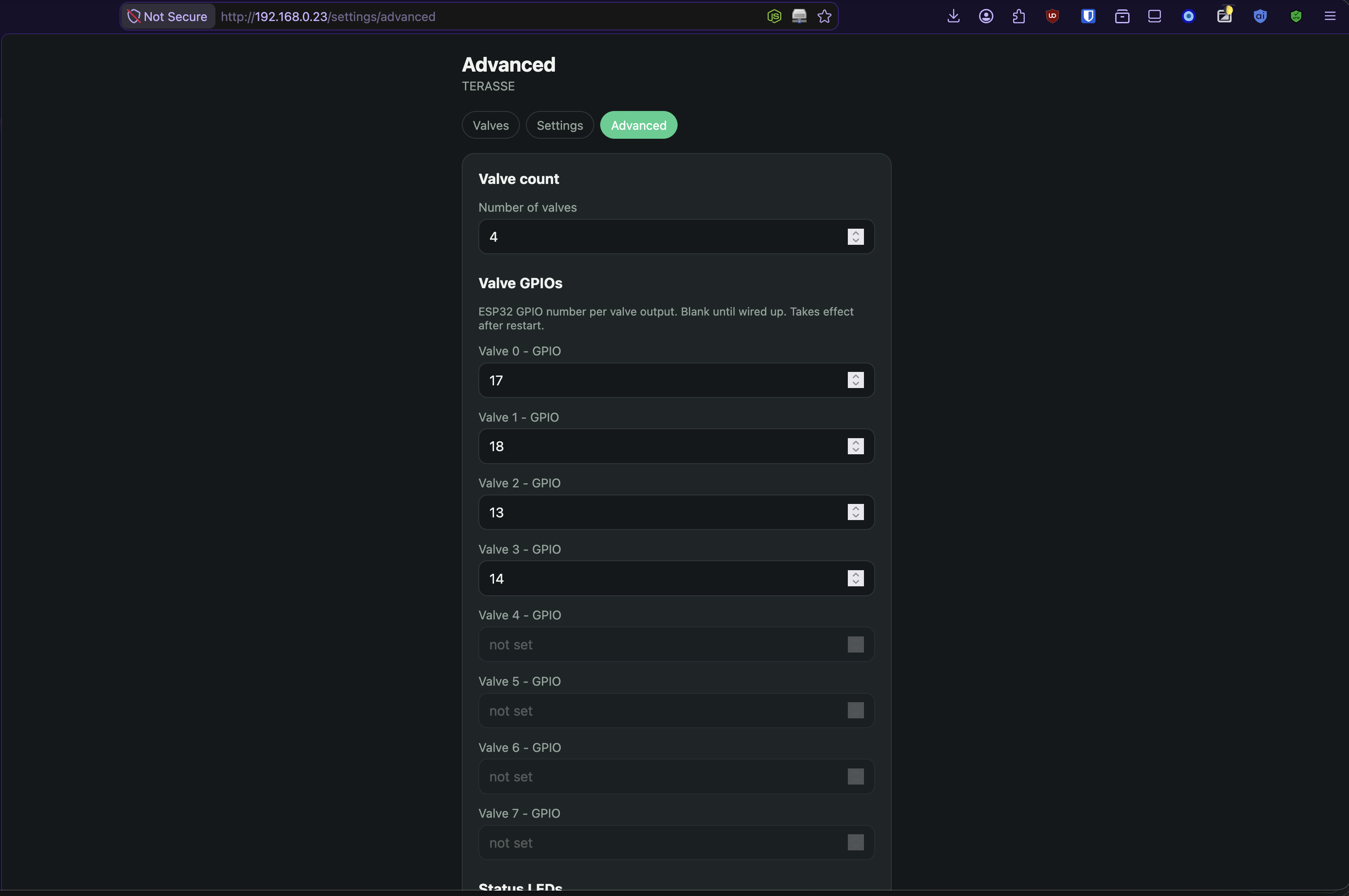 |
- WiFi setup via its own access point. Once WiFi's configured, the device drops the AP and is just a normal device on your network. The same web UI is reachable there.
- Config lives in the web UI: device name, MQTT broker, discovery namespace, valve count, GPIO per valve, status LED GPIOs.
- Home Assistant MQTT auto-discovery: One switch entity per valve, no YAML.
- Plain HTTP API alongside MQTT (valve count, per-valve state, on/off).
- Supports 1–8 individual valves.
- Optional status LEDs (WiFi, MQTT, per-valve), independently wireable, can be disabled without losing their GPIO config.
- Valve runtime failsafe (configurable timeout forces a valve off if left on too long), all valves shut off on WiFi/MQTT disconnect.
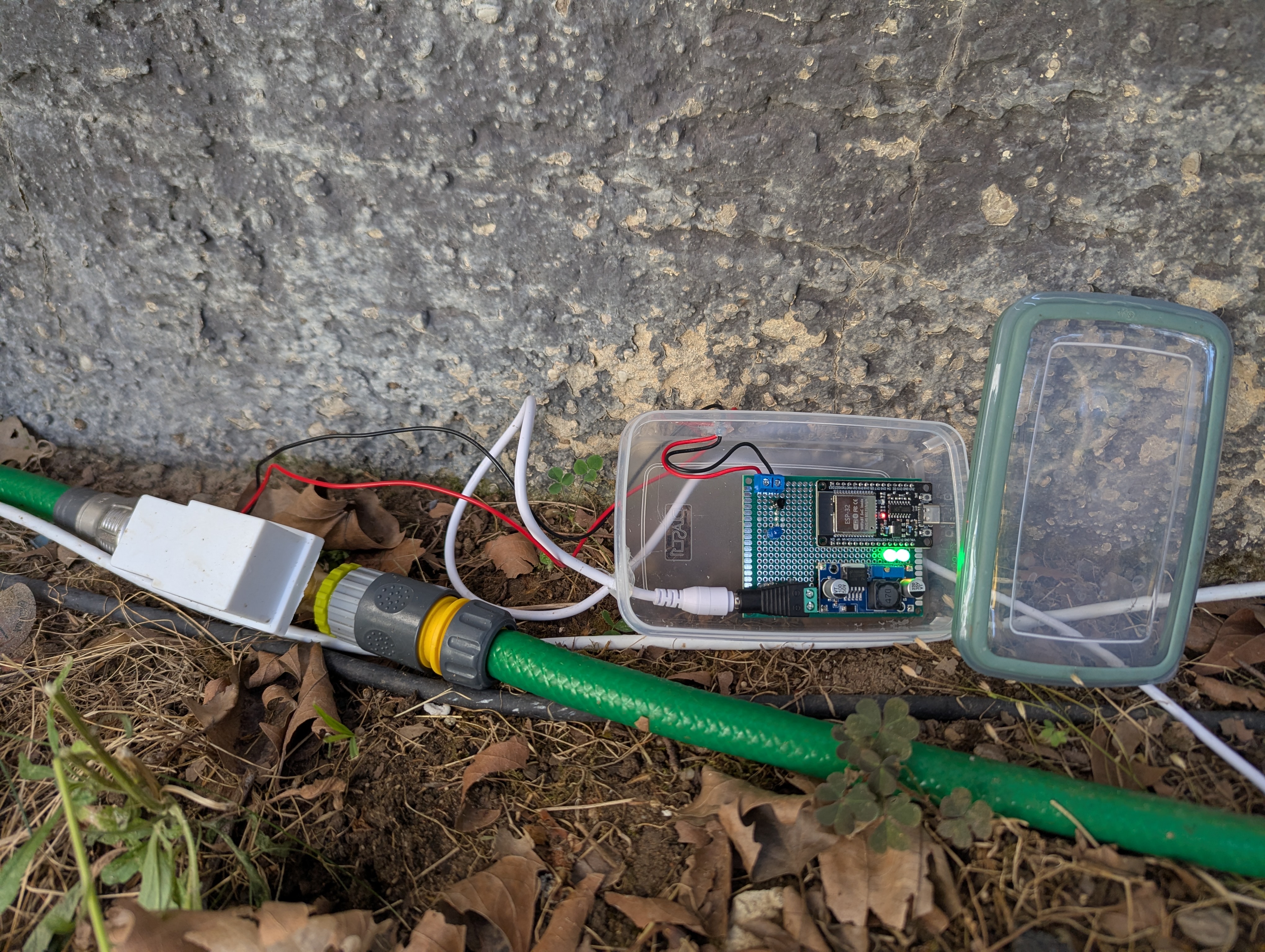
- ESP32 dev board
- Protoboard
- Jumper wires
- Buck converter (steps 12V down to 5V for the ESP32)
- 12V DC power supply, at least 1000mA + 500mA per additional valve
Optional: two status LEDs + resistors (board built with green LEDs, 120Ω)
- 12V DC solenoid valve with garden hose adapters
- 1N4007 diode (flyback protection)
- 270Ω resistor (transistor base)
- 2N2222 transistor (low-side switch)
Optional: one status LED + resistor per valve (board built with a blue LED, 120Ω)
Base (one of each):
- ESP32 dev board
- Protoboard
- Jumper wires
- Buck converter, 12V → 5V
- 12V DC power supply, ≥ 1000mA + 500mA per additional valve
- (optional) 2× LED + resistor for board status (green, 120Ω in this build)
Per valve, multiply by however many valves you're building (1–8):
- 12V DC solenoid valve + garden hose adapters
- 1N4007 diode
- 270Ω resistor
- 2N2222 transistor
- (optional) 1× LED + resistor for valve status (blue, 120Ω in this build)
flowchart LR
    PSU["12V DC PSU"]
    BUCK["Buck converter<br/>12V to 5V"]
    ESP["ESP32"]
    GNDHIGH(("GND high<br/>before buck, 12V return"))
    GNDLOW(("GND low<br/>after buck, 5V/logic return"))

    PSU -->|"12V+"| BUCK
    BUCK -->|"5V+"| ESP
    PSU -.->|GND| GNDHIGH
    BUCK -.->|"GND in"| GNDHIGH
    BUCK -.->|"GND out"| GNDLOW
    ESP -.->|GND| GNDLOW
    GNDHIGH ---|"bonded, same net"| GNDLOW

    subgraph VALVE["Per valve"]
        SOLP["Solenoid +"]
        SOLN["Solenoid -"]
        DIODE["1N4007<br/>cathode toward +12V side"]
        Q["2N2222<br/>collector/emitter"]
        RB["270 ohm"]
    end

    PSU -->|"12V+"| SOLP
    SOLP --- SOLN
    SOLN -.->|"flyback diode, in parallel with coil"| DIODE
    DIODE -.-> SOLP
    SOLN --> Q
    Q -->|"emitter"| GNDHIGH
    ESP -->|"GPIOn"| RB --> Q

    subgraph LEDS["Optional status LEDs"]
        LW["WiFi OK LED<br/>green, 120 ohm"]
        LM["MQTT OK LED<br/>green, 120 ohm"]
        LV["Valve LEDs (one per Valve)<br/>blue, 120 ohm"]
    end

    ESP -->|GPIO| LW
    ESP -->|GPIO| LM
    ESP -->|GPIO| LV
    LW -.->|GND| GNDLOW
    LM -.->|GND| GNDLOW
    LV -.->|GND| GNDLOW
Front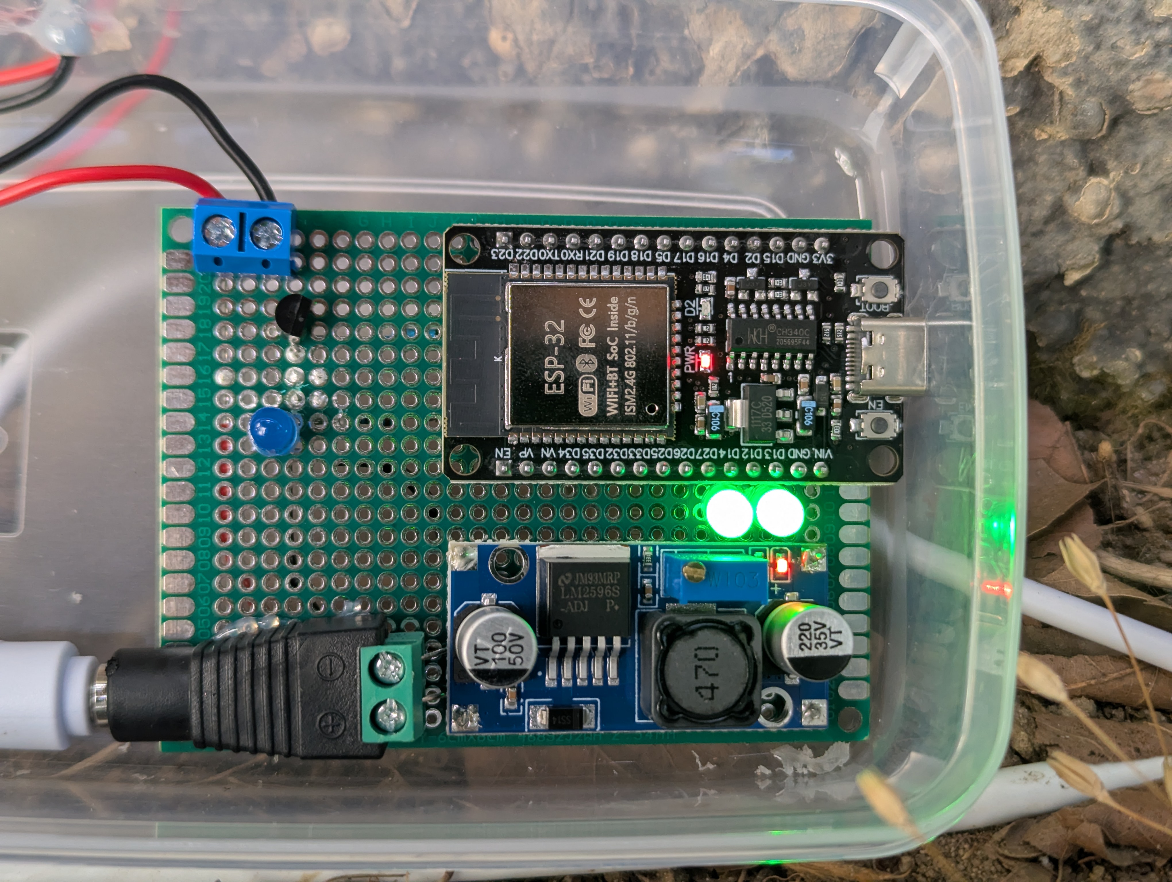 |
Back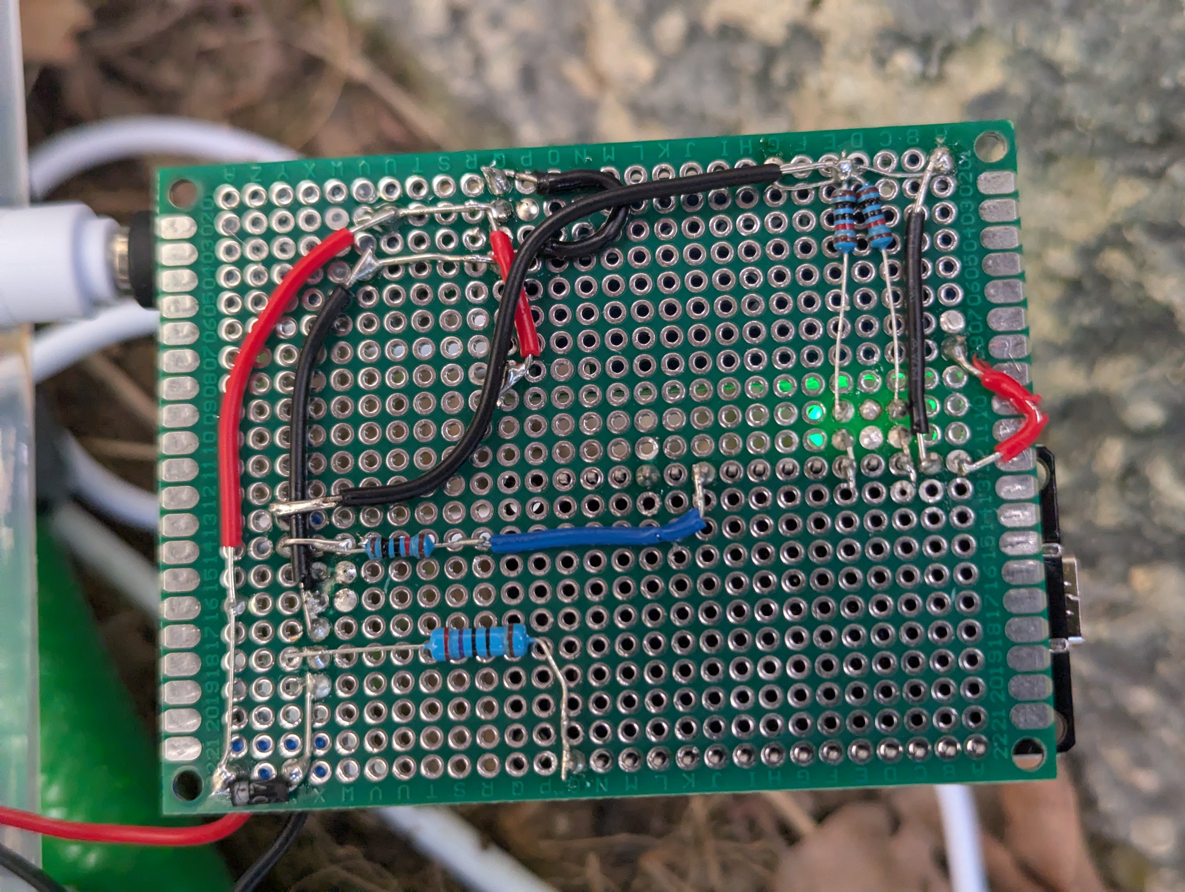 |
In words:
- Power: 12V PSU feeds the buck converter, which steps down to 5V into the ESP32's 5V/VIN pin. The 12V PSU also feeds the solenoids directly (they run on 12V, not 5V).
- Per valve: one leg of the solenoid coil goes to 12V+. The other leg goes to the 2N2222's collector, and also has the 1N4007 flyback diode wired across the coil (cathode/banded end toward +12V, anode toward the collector) to absorb the voltage spike when the coil switches off. The transistor's emitter goes back to GND high, the ground point on the 12V/PSU side, before the buck converter, not through the buck. The base goes to an ESP32 GPIO through a 270Ω resistor, the ESP32 switches the valve by driving that GPIO high/low (low-side switching).
- Optional valve LED: GPIO → resistor → LED → GND low (the buck's 5V output-side ground, same as the ESP32's).
- Optional board status LEDs (WiFi-OK, MQTT-OK): same pattern, GPIO → resistor → LED → GND low.
- Why two ground labels: on a standard non-isolated buck converter, GND high and GND low are the same electrical net, but it's still worth routing deliberately rather than just grabbing whichever ground pad is closest. The solenoids' switching current is comparatively large and returns straight to GND high (near the PSU), instead of routing through the buck's own ground pins. That keeps that switching noise off the ground reference the buck's regulation loop and the ESP32's logic actually use (GND low), cheap insurance against noise coupling, sometimes called star grounding. The low-current status LEDs don't carry enough current for this to matter, so they just return to GND low.
- If something doesn't light: check continuity between GND high and GND low with a multimeter (should read ~0Ω), if they're not actually bonded, nothing wired across the two domains will work, no matter how correct the rest of the circuit is.
GPIO pins aren't fixed anywhere, every valve and LED GPIO is assigned from the web UI after flashing. GPIO34/35/36/39 are input-only and can't drive anything; pick a different pin for any output (LED or transistor base). GPIO0 is reserved for the onboard BOOT button (see Resetting WiFi); don't assign it to a valve or LED.
Requires ESP-IDF (built against v6.0.1) targeting esp32.
idf.py set-target esp32
idf.py build
idf.py -p /dev/tty.YOUR_PORT flash monitorNo WiFi configured yet → the device opens its own access point (Irrigation-Setup-XXXXXX) with a captive portal. Same thing happens after a WiFi reset.
- Connect a phone or laptop to that access point.
- Setup page pops up automatically (captive portal); if it doesn't, go to
http://192.168.4.1/. - Pick your WiFi network, enter the password, optionally set a device name.
- Connect: device reboots onto your WiFi.
From here on the AP is gone and the device just sits on your network. Same web UI, now reachable at whatever IP your router hands it.
Find the device's IP (router's client list) and open it in a browser. Three tabs:
- Valves - toggle switches with live on/off status
- Settings - device name, MQTT broker/user/password, MQTT/HA discovery node ID, max valve runtime failsafe
- Advanced - number of valves, GPIO per valve, GPIO per status LED, checkboxes to disable the WiFi/MQTT LEDs or the valve LEDs as a group without losing their GPIO assignment
Every save restarts the device to apply the change. Growing the valve count is two saves: save the new count and let it restart once (that's what reveals GPIO fields for the new valves), then fill those in and save again.
Hold the onboard BOOT button for 5 seconds while powering on: wipes the stored WiFi credentials, drops back into setup-AP mode.
MQTT configured → the device publishes HA discovery for each valve automatically, no YAML. The discovery/ACL namespace ("Discovery node ID" on the Settings page, defaults to garden_devices) is meant to be shared across a fleet of controllers, so one broker ACL rule (homeassistant/switch/<node id>/#) covers all of them. Give every controller the same value unless you're deliberately splitting ACL scopes.
<device> is the device name from Settings, <node id> the discovery node ID, <n> the valve index (0-based). Payloads are the plain strings ON/OFF unless noted.
| Topic | Direction | Purpose |
|---|---|---|
cmnd/irrigation/<device>/<n>/POWER |
subscribe | Sets valve <n>, send ON/OFF. The device subscribes to this per valve on connect. |
stat/irrigation/<device>/<n>/POWER |
publish, retained | Reports valve <n>'s actual state, published on every state change and once per valve right after connecting. |
tele/irrigation/<device>/LWT |
publish, retained | Availability: Online on connect, Offline as the MQTT last-will if the device drops off ungracefully. |
homeassistant/switch/<node id>/<device>_<n>/config |
publish, retained | Home Assistant discovery payload for valve <n> (JSON, points HA at the two topics above). |
To drive a valve from any MQTT client without Home Assistant, publish ON/OFF to its cmnd/.../POWER topic and read back state from the matching stat/.../POWER topic.
Same endpoints the web UI itself uses: plain text (key=value lines) for reads, URL-encoded form bodies for writes, no MQTT broker needed. There's no authentication on any of these. Anyone on your IoT-VLAN who can reach the device can use them. <n> is the valve index (0-based, < num_valves).
Valve control:
| Endpoint | Method | Response | Purpose |
|---|---|---|---|
/api/valve/status |
GET | 0:1\n1:0\n... |
State of every configured valve, one idx:state line each (1/0). |
/api/valve/<n>/open |
POST | empty body; 400 if <n> isn't a configured valve, 500 on a hardware failure |
Opens valve <n>. |
/api/valve/<n>/close |
POST | same as above | Closes valve <n>. |
Configuration (the same fields the Settings/Advanced pages read and save; every successful write here restarts the device to apply it, exactly like saving from the web UI):
| Endpoint | Method | Body / Response | Purpose |
|---|---|---|---|
/api/valve/config |
GET | num_valves=4\ngpio0=16\n... |
Valve count and actuator GPIO per valve. |
/api/settings |
GET | device_name=...\nmqtt_uri=...\n... |
Settings-page fields (password fields are reported as ..._password_set=1/0, never the value itself). |
/api/settings/advanced |
GET | num_valves=...\ngpio0=...\nwifi_led_gpio=...\n... |
Advanced-page fields (valve/LED GPIO assignments, LED enable flags). |
/settings |
POST | form body: device_name, max_valve_runtime_min, enable_runtime_safety, enable_cut_on_wifi_loss, enable_cut_on_mqtt_loss, mqtt_uri, mqtt_user, mqtt_pass, node_id |
Saves the Settings page. Blank mqtt_pass keeps the currently stored password. |
/settings/advanced |
POST | form body: num_valves, gpio0..gpio7, valve_led_gpio0..valve_led_gpio7, wifi_led_gpio, mqtt_led_gpio, enable_conn_leds, enable_valve_leds |
Saves the Advanced page. |
/api/wifi |
POST | form body: ssid, password |
Sets WiFi credentials (used by the onboarding/setup page). Blank password keeps the currently stored one. |
curl http://<device-ip>/api/valve/status
curl -X POST http://<device-ip>/api/valve/0/open- This drives 12V solenoids and mains-adjacent wiring. If you're not comfortable with basic electronics/wiring safety, get someone who is to check your build before powering it on.
- The flyback diode across each solenoid coil is not optional, switching an inductive load without one will eventually damage the transistor (and possibly the ESP32).
- Size your 12V PSU for worst case: all valves energized simultaneously, plus the buck converter's own draw.