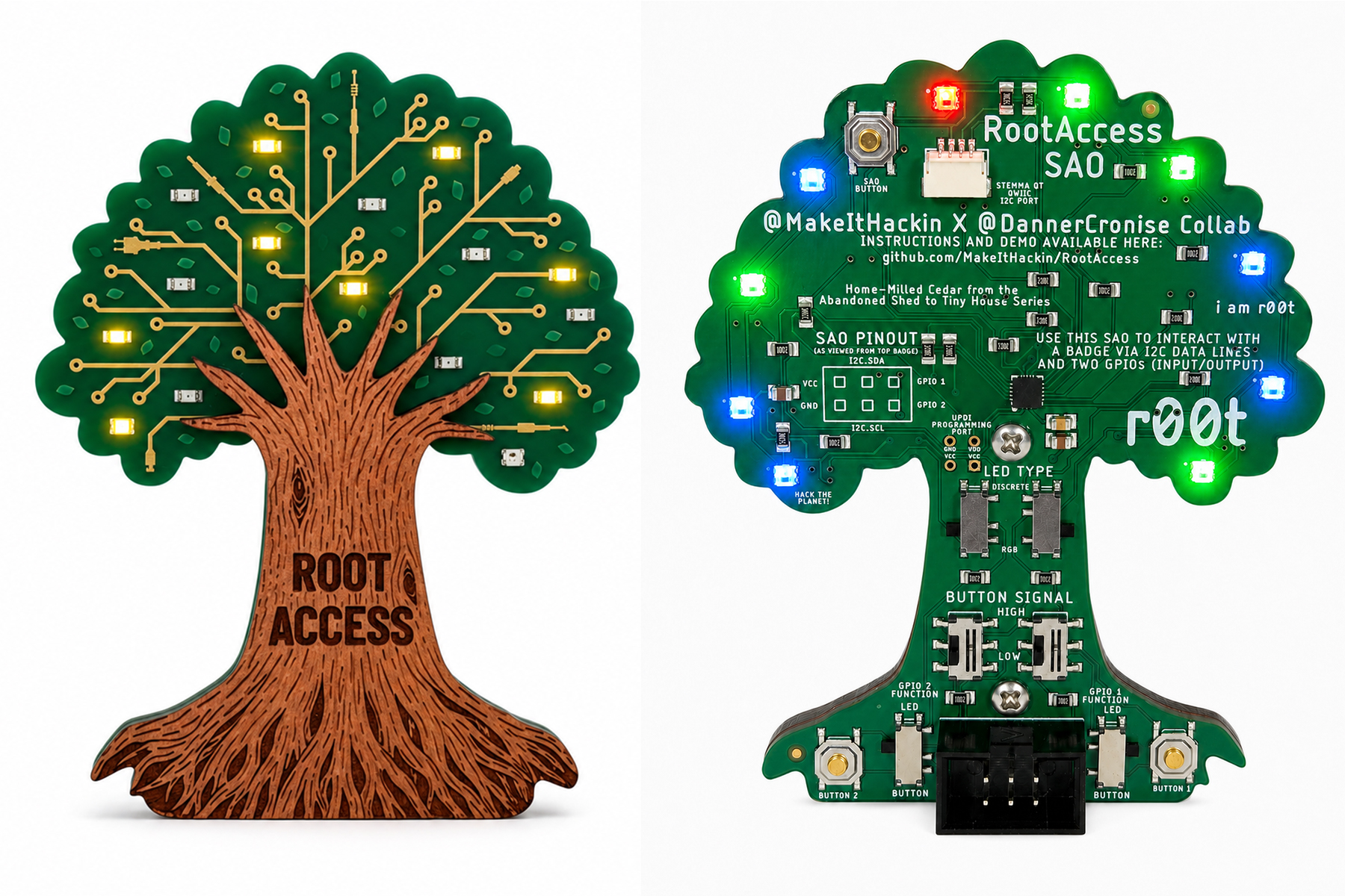
This document covers everything needed to operate the RootAccess board: as a
standalone device using its physical button, and as an I2C peripheral
controlled from any host (Arduino, ESP32, Raspberry Pi, Linux i2c-dev,
anything that can speak I2C).
YouTube Demonstration:
Purchase Here:
- https://uberflux.com/product/MIH-RootAccessSao
- https://makeithackin.myshopify.com/products/root-access-sao
- MCU: ATtiny1616
- I2C address:
0x50 - NeoPixels: 10, individually addressable RGB
- Discrete LED pins: 11 general-purpose pins, at internal pin indices
0, 1, 2, 3, 4, 5, 6, 7, 14, 15, 16 - PWM-capable pins (dimmable):
0, 1, 7, 16— these 4 accept a 0-255 brightness value. The other 7 discrete pins are on/off only. - Physical button: one pushbutton, supports tap / 700ms hold / 3s hold (see below)
The board runs entirely on its own if nothing is connected to I2C. All control is via the single pushbutton:
| Action | Result |
|---|---|
| Quick tap | Advances to the next animation mode (wraps from the last mode back to the first). If the device is currently off, a tap instead resumes whatever animation was playing before it turned off — it does not just restart at mode 0. |
| Hold ~700ms | Turns everything off — all discrete LEDs and NeoPixels go dark. This is a distinct state, not part of the normal tap-cycle sequence; you can't tap your way into "off," only reach it via this hold (or an I2C command — see Part 2). |
| Hold ~3 seconds | Saves whichever animation was playing before you started holding as the boot-time favorite, confirms with three quick white blinks across the NeoPixels, then resumes that animation. Holding past the 700ms off-point on the way to 3s is expected — the LEDs go dark momentarily, then the confirmation blink and resume happen once you reach 3s. |
On power-up, the board boots into, in priority order:
- The saved favorite (if one has ever been set via the 3s hold)
- Otherwise, whatever animation was last playing when it lost power
- Otherwise (brand new/never used), animation 0
Both the favorite and the last-played mode are stored in the chip's non-volatile memory (USERROW) and survive power loss and firmware re-flashes — they're not reset by uploading new code to the board.
Wire your host's I2C SDA/SCL to the board (plus a shared ground), and talk
to address 0x50. The board has been verified working at 100kHz (I2C
standard mode); there's no reason to expect trouble at higher speeds either,
but 100kHz is the validated baseline.
The board is always an I2C slave — it never initiates communication. Everything is either the host writing a command, or the host reading back a 2-byte status response.
There are four categories of command, all sent as a plain I2C write (no register-address preamble — just write the bytes described below directly):
- Select a built-in animation (single byte, 0-49)
- Turn everything off (single byte, 50)
- Pause / hand control to the host without an immediate raw command (single byte, 51-255, other than the two raw-control opcodes below)
- Raw LED control — set every individual LED yourself (
0xFDand0xFC)
Write a single byte, 0-49, to run one of the board's 50 built-in animation patterns. The board takes over the animation from that point — no further host involvement needed.
| Byte (dec) | Byte (hex) | Animation |
|---|---|---|
| 0 | 0x00 | Ambient Soft Rainbow with Dedicated PWM Fading vs. Clean Digital Pins |
| 1 | 0x01 | Pure Digital Strobe Simulator |
| 2 | 0x02 | Theater Chase White |
| 3 | 0x03 | Ping-Pong Chase Loop |
| 4 | 0x04 | Breathing Pulse |
| 5 | 0x05 | The "Newton's Cradle" Ball Clicker |
| 6 | 0x06 | Color Wipe Red |
| 7 | 0x07 | Ignition & Exhaust (Flicker Fire + PWM Throttle) |
| 8 | 0x08 | Raindrops on a Window |
| 9 | 0x09 | Strandtest Classic Rainbow |
| 10 | 0x0A | Original Hybrid Combined Suite |
| 11 | 0x0B | Random Single Blink |
| 12 | 0x0C | Theater Chase Red |
| 13 | 0x0D | Twin Scan Mirror |
| 14 | 0x0E | The Pulse Wave (Radial Soundwave Sim) |
| 15 | 0x0F | Cellular Automation (Game of Life 1D) |
| 16 | 0x10 | Color Wipe Green |
| 17 | 0x11 | Independent Candle Flicker (Chaotic Individual Pixel Noise) |
| 18 | 0x12 | The Matrix Rain (Digital Rainstorm) |
| 19 | 0x13 | Rainbow Cycle |
| 20 | 0x14 | Even / Odd Pin Array Alternator |
| 21 | 0x15 | Random Double Blink |
| 22 | 0x16 | Theater Chase Blue |
| 23 | 0x17 | Marquee Chase (Every 3rd LED) |
| 24 | 0x18 | Heartbeat Monitor (EKG Tracker Routine) |
| 25 | 0x19 | Hourglass Sand Dropper |
| 26 | 0x1A | Color Wipe Blue |
| 27 | 0x1B | Synchronized Candle Flicker (Unified Global Drop) |
| 28 | 0x1C | Shooting Star Meteor Shower |
| 29 | 0x1D | Live Binary Value Counter |
| 30 | 0x1E | Random Triple Blink |
| 31 | 0x1F | Theater Chase Rainbow |
| 32 | 0x20 | Knight Rider / Cylon Scan (Synced Spatial Track) |
| 33 | 0x21 | Overlapping Sine Waves (Independent Fixed-Point Breathing) |
| 34 | 0x22 | The Casino Roulette Wheel |
| 35 | 0x23 | The Chroma RootAccess Swarm |
| 36 | 0x24 | Center-Out Explosion Wave |
| 37 | 0x25 | Random Static Flicker |
| 38 | 0x26 | Collision Chase |
| 39 | 0x27 | Ocean Tide & Undertow |
| 40 | 0x28 | Vintage Hard Drive Defrag Sim |
| 41 | 0x29 | The Slashing Laser Saber (Ignition / Plasma Arc) |
| 42 | 0x2A | Random Quadruple Blink |
| 43 | 0x2B | Audio Visualizer / VU Meter Simulator |
| 44 | 0x2C | Growing Memory Sequence (Simon-style reveal) |
| 45 | 0x2D | Cascade Filling Bucket |
| 46 | 0x2E | Tesla Coil Arc Storm |
| 47 | 0x2F | Target Radar Scan |
| 48 | 0x30 | Police Animation (Strobe Blue 0-4 vs Red 5-9) |
| 49 | 0x31 | All On (Discrete Pins HIGH, NeoPixels White) |
Example: to run "Rainbow Cycle" (mode 19), write the single byte 19
(0x13) to address 0x50.
Write the single byte 50 (0x32). Equivalent to the physical 700ms hold —
all discrete LEDs and NeoPixels go dark. This is a real, addressable mode,
not just a "pause" — same effect as the button.
Writing any single byte from 51-255, other than 0xFD or 0xFC, tells
the board to stop running its current animation and go dark, without
selecting a specific new mode. This is mostly useful as a legacy/simple
"stop" signal; in most cases you'll want Command 2 (byte 50) instead, since
it does the same thing and is a properly defined mode.
This is the advanced mode: bypass all built-in animations and drive every discrete pin and every NeoPixel yourself. It's two separate commands (see "Why two commands" below) — send either independently, or both if you want to update everything.
Write exactly 12 bytes:
| Byte offset | Meaning |
|---|---|
| 0 | Opcode 0xFD |
| 1 | Pin 0 — PWM capable, send 0-255 for brightness |
| 2 | Pin 1 — PWM capable, 0-255 |
| 3 | Pin 2 — on/off only: 0 = off, any nonzero = on |
| 4 | Pin 3 — on/off |
| 5 | Pin 4 — on/off |
| 6 | Pin 5 — on/off |
| 7 | Pin 6 — on/off |
| 8 | Pin 7 — PWM capable, 0-255 |
| 9 | Pin 14 — on/off |
| 10 | Pin 15 — on/off |
| 11 | Pin 16 — PWM capable, 0-255 |
The order (pin indices 0,1,2,3,4,5,6,7,14,15,16) is fixed — always send
11 bytes in this exact position order. You don't need to track which
positions are PWM-capable yourself; just send a 0-255 value everywhere, and
the board applies dimming where the hardware supports it and treats
nonzero-as-on everywhere else.
Example (hex): turn pin 0 to half brightness, pin 2 on, everything else off:
FD 80 00 01 00 00 00 00 00 00 00 00
Write exactly 31 bytes:
| Byte offset | Meaning |
|---|---|
| 0 | Opcode 0xFC |
| 1-3 | Pixel 0: R, G, B |
| 4-6 | Pixel 1: R, G, B |
| 7-9 | Pixel 2: R, G, B |
| ... | ... |
| 28-30 | Pixel 9: R, G, B |
Ten pixels, three bytes each (red, green, blue, each 0-255), no gaps, pixel 0 first.
Example (hex): set pixel 0 to full red, pixel 1 to full green, the rest off:
FC FF 00 00 00 FF 00 00 00 00 00 00 00 00 00 00 00 00 00 00 00 00 00 00 00 00 00 00 00 00 00
(1 opcode byte + 3 bytes for pixel 0 + 3 for pixel 1 + 24 zero bytes for pixels 2-9 = 31 bytes total.)
A single combined command (opcode + 11 discrete + 30 NeoPixel bytes = 42 bytes) doesn't fit in the board's 32-byte I2C buffer, and that buffer size can't safely be changed from application code on this platform. Splitting into two independent, smaller commands avoids the problem entirely — both fit comfortably under 32 bytes. Practical effect: if you want to update everything at once, send both commands back-to-back (two I2C transactions). There's a very brief window between them (well under a millisecond) where only one half has updated — imperceptible for almost any use case.
Sending either raw-control command puts the board into the same "host-controlled" state as Command 3 — it stops running its own animation and holds whatever you told it to show. Your values persist until you send another command. To hand control back to the built-in animations, send Command 1 (a mode byte 0-49) or Command 2 (off, byte 50).
The physical button still works independently at all times and can override raw control — e.g. someone tapping the button will switch it back to a built-in animation.
After any command (mode-select, off, pause, or either raw-control
command), you can do a follow-up I2C read of 2 bytes from 0x50:
| Byte | Meaning |
|---|---|
| 0 | The last mode byte the board processed (0-50). Not meaningful for raw-control commands — safe to ignore in that case. |
| 1 | Status: 1 = last command accepted, 0 = last command was malformed and rejected |
The only way to get a 0 status is sending the wrong number of bytes for a
raw-control command (anything other than exactly 12 bytes after 0xFD, or
exactly 31 bytes after 0xFC). On rejection, the board changes nothing —
whatever it was doing before is completely unaffected. There's no partial
application; each command is all-or-nothing.
Reading the response is optional and has no side effects — you can read it zero, one, or several times after a command with no risk to the board's state (each read just reports the two variables' current values; nothing is consumed or cleared by reading).
| You send (dec) | You send (hex) | Board does |
|---|---|---|
0-49 |
0x00-0x31 |
Runs that built-in animation |
50 |
0x32 |
Turns everything off |
51-255 (except 0xFD/0xFC) |
0x33-0xFF (except 0xFD/0xFC) |
Generic pause (goes dark, no specific mode selected) |
0xFD + 11 bytes (12 total) |
0xFD + 11 bytes (12 total) |
Sets all 11 discrete pins directly |
0xFC + 30 bytes (31 total) |
0xFC + 30 bytes (31 total) |
Sets all 10 NeoPixels directly |
| (read 2 bytes) | Byte 0 = last mode processed, byte 1 = status (1 OK / 0 malformed) |