Home
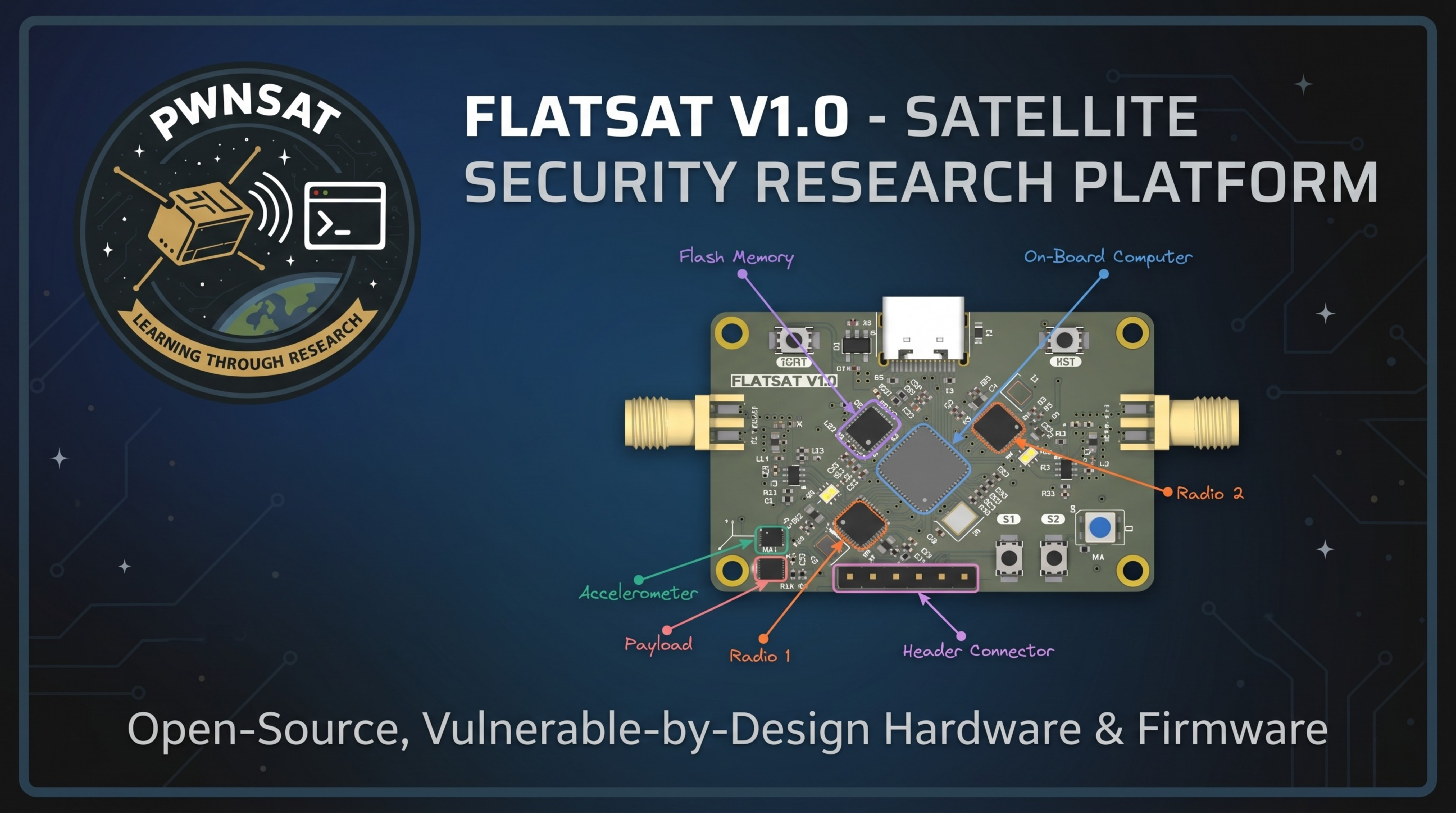
The world’s first open-source, dual-core hardware platform vulnerable-by-design, engineered specifically to learn aerospace cybersecurity adn satellite hacking.
Welcome to the official FlatSat v1.0 documentation hub. FlatSat is an open-source, dual-core hardware-in-the-loop (HIL) platform designed to simulate satellite sub-systems, orbital telemetry, and real aerospace communication protocols.
Developed as a community-driven project for satellite cybersecurity training, firmware prototyping, and aerospace CTFs (Capture The Flag), FlatSat provides a hands-on, un-sanitized environment for discovering, exploiting, and mitigating vulnerabilities in space systems.
Warning
RF Compliance & Safety Notice FlatSat operates within standard license-free ISM bands (433 MHz / 915 MHz). Users must strictly adhere to local amateur radio and telecommunications regulations regarding transmission power, duty cycles, and frequency allocation.
The processing core relies on the Raspberry Pi RP2040 dual-core ARM Cortex-M0+ microcontroller implementing Asymmetric Multiprocessing (AMP) to divide mission critical tasks:
- Core 0 (Flight Operations): Runs the primary satellite main loop, manages real-time sensor updates, handles active telemetry/telecommand state registers, and drives the hardware SPI buses connected to the radio modules.
-
Core 1 (Diagnostics Interface): Dedicated exclusively to maintaining high-speed payload data pipelines over the USB interface utilizing the TinyUSB stack (
usbCDC). This isolates communication overhead from freezing the flight software running on Core 0.
FlatSat integrates dedicated peripherals over its internal lines to emulate actual space telemetry packets:
-
Attitude Determination: A LIS2DH12 3-axis accelerometer connected via the primary
I2Cbus tracks simulated coordinate and tilt vectors. - Environmental Metrics: A BME280 sensor samples ambient temperature, barometric pressure, and relative humidity parameters.
-
Asynchronous Execution: Rather than calling blocking delay functions, the system schedules sensor reads dynamically using an advanced non-blocking
timeout_worker_tinfrastructure to keep interfaces continuously open.
The communication hardware is built out to support separate uplink and downlink RF configurations natively:
- Transceivers: Dual independent Semtech SX1262 sub-GHz LoRa modules routed via hardware control pins on the shared SPI0 bus interface.
- Radio 0 (Uplink Channel): Fixed to function as a receiver, continuously waiting to capture over-the-air Telecommands (TC).
- Radio 1 (Downlink Channel): Fixed to function as a transmitter, broadcasting periodic Telemetry (TM) frames or acknowledging requests.
-
Protocol Framing: Data frames map directly to the CCSDS Space Packet Protocol standard layout. Packets are parsed via the internal
spp_unpack_packetand routed downstream through application process identifiers (APIDs) without cryptographic verification.
A designated physical Header Connector breaks out internal copper lines directly for bus analysis:
-
Sniffing Ports: Pins expose the active
UARTserial logs, the primaryI2Cline, and the rawSWDdebug interface, allowing operators to hook up logic analyzers for direct hardware monitoring or hardware debugging.
Note
- 01. Getting Started: Firmware Compilation & Testing: Your entry point. Setting up the ARM toolchain, compiling the source code, flashing the RP2040, and verifying hardware sanity via local or RF links.
- 02. Hardware Anatomy & Specifications: Physical layout, schematic analysis, pinouts, and exposed debugging interfaces (UART, I2C, SWD) for hardware auditing.
- 03. Firmware & System Architecture: Deep dive into the Asymmetric Multiprocessing (AMP) architecture. How Core 0 (Flight operations) and Core 1 (TinyUSB telemetry bridge) divide tasks.
- 04. Space Packet Protocol (CCSDS): Aerospace communication standards, packet encapsulation structure, and the live APID routing registry.
- 05. Satellite Hacking & Attack Vectors: [THE OFFENSIVE PLAYGROUND] Exploitation vectors. Packet fuzzing, telecommand spoofing, buffer overflows in packet lengths, and unauthorized subsystem manipulation.
- 06. Attack Walkthroughs (00-07): Step-by-step: prerequisites, the exact command, and how to confirm each of the 8 validated attacks worked against real hardware.
- Main Repository: Pwnsat/FlatSat
- Firmware Core: Pwnsat/FlatSat_Firmware
- Latest Stable Release: FlatSat Firmware v1.0.0