Disassembly, control flow and LLIL lifting for the PIC16 mid-range cores (14-bit words) and the 12-bit baseline core, plus loaders for flat program memory images that work out which core, and which part, they are looking at.
| Architecture | Core | Parts |
|---|---|---|
pic16 |
enhanced mid-range, 14-bit | PIC16F1xxx |
pic16-classic |
classic mid-range, 14-bit | PIC16F87xA, PIC16F84A and friends |
pic16-baseline |
baseline, 12-bit, 512 words, no paging | PIC16C54, PIC16C55, PIC1650, PIC1654, PIC1655 |
pic16-baseline-paged |
baseline, 1024 words in two pages | PIC16C56 |
pic16-baseline-banked |
baseline, 2048 words in four pages, four RAM banks | PIC16C57 |
The two mid-range architectures are dialects of one instruction set and share
almost all their code. The baseline ones are a different instruction set
that happens to carry the same family name, and live under pic16arch/baseline/;
see The 12-bit baseline core.
Written while reverse-engineering one enhanced-core firmware image, then generalised against a corpus of 170 PIC ROM dumps from MAME, which is where most of the behaviour described below was settled. The figures quoted through this file come from real images.
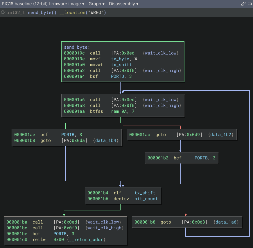
Binary Ninja loads 3rd party plugins that aren't in the plugin manager
inventory from ~/.binaryninja/plugins on sane systems; check
binaryninja.user_plugin_path() if you are on a less sane one. Symlink
pic16arch in rather than copying it, for easier management.
mkdir -p ~/.binaryninja/plugins
ln -s "$PWD/pic16arch" ~/.binaryninja/plugins/pic16arch
Binary Ninja loads plugins at startup, so restart it after adding the link or after changing any file in the plugin.
If it does not work, open Binary Ninja's log window. The plugin writes a traceback there when registration or image loading fails, naming what it was doing at the time.
The PIC16 is a Harvard machine with three spaces, none byte-addressed the way Binary Ninja expects. Each gets a window in Binary Ninja's single flat space:
| PIC space | Binary Ninja addresses | Mapping |
|---|---|---|
| Program memory | 0x00000000-0x0000FFFF |
word address × 2 |
| Data memory (banked RAM + SFRs) | 0x00100000-0x00100FFF |
linear data address |
| Hardware call stack | 0x00200000-0x002000FF |
synthetic; see below |
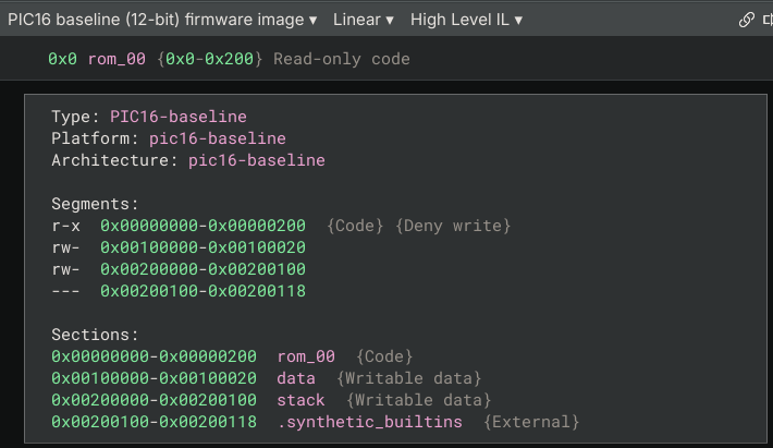
The data window is 12 bits wide for the enhanced core's 32 banks and 9 bits
(0x00100000-0x001001FF) for the classic core's four, so an access computed
from a bank the part does not have lands visibly outside the map.
Erased flash is mapped readable but not executable, and the program
segment is split into runs to arrange it. Otherwise a linear sweep walks into
a large erased region (every word a valid, falling-through MOVWI) and
manufactures one enormous function. In one 8K-word image that was a single
1989-word "function", and it dominated analysis time. The runs it finds there
are exactly the image's own code and blank regions:
word 0x0C00..0x0FFA  1018 words  code
word 0x0FFA..0x129E   676 words  erased
word 0x129E..0x1800  1378 words  code
word 0x1800..0x1FBF  1983 words  erased
word 0x1FBF..0x1FE0    33 words  code
Program addresses are doubled. Word 0x0C00 in a datasheet or an MPLAB
listing is 0x1800 here. This is not a choice so much as the only workable
option: a 14-bit word needs two bytes, and Binary Ninja addresses bytes. It
has one happy consequence: a flat image dump and an Intel HEX file for these
parts already use exactly this layout, so nothing has to be transformed at
load time.
The hardware stack is not addressable on the real part at all. It exists here
only because Binary Ninja wants a stack pointer to reason about calls with;
the synthetic SP register and its window are never touched by real code.
Two PIC16 quirks make context-free disassembly frustrating, and both are things the IL can fix.
Banking. A byte-oriented instruction carries only a 7-bit file offset; the
rest of the data address comes from elsewhere. Disassembly cannot know the
bank, so the text says [BSR:0x2c] or [RP:0x2c]. But the bank source lifts
to a plain register and the address is lifted as an explicit sum, so Binary
Ninja's constant propagation resolves it. In MLIL and HLIL you get the named
register (TRISC, SSPCON1, PIR1) wherever the bank is knowable.
On the enhanced core the bank source is BSR, loaded outright by MOVLB. On
the classic core it is STATUS<6:5>, RP1:RP0, and BANKSEL sets those one bit
at a time with BCF/BSF. So RP0, RP1 and IRP are modelled as one-bit
registers rather than as bits of a STATUS byte: BCF STATUS, RP0 then
becomes RP0 = 0, an assignment dataflow can fold, where a read-modify-write
of a byte whose prior value is unknown would stay unknown forever. Reads and
writes of STATUS as a whole (the SWAPF STATUS, W context save every classic
ISR opens with) compose and decompose those registers, so the bank survives
the round trip.
Paging. CALL and GOTO carry only PC<10:0>; the rest comes from PCLATH:
bits 6:3 on the enhanced core, 4:3 on the classic one, which has a 13-bit PC.
On the enhanced core MOVLP loads it; the classic core has no such
instruction and uses MOVLW k / MOVWF PCLATH. Same treatment either way:
the text shows PCLATH:0x44a, the IL computes the full target from the
PCLATH register, and dataflow turns it into a real edge and a real
cross-reference. That is the difference between a listing that prints raw
11-bit target values and one that says where the transfer actually goes.
Dataflow gets every branch a MOVLP reaches, which is every cross-page
transfer, because the hardware requires a MOVLP before one. It does not get
an intra-page GOTO inside a subroutine that never loads PCLATH itself: there
PCLATH holds whatever the caller left, and dataflow sees an unknown register.
In a typical application image that is most of them. One 5088-word example
has 274 of its 323 branches in that state.
paging.py recovers those, and not by guessing. To have reached a function at
word address T at all, the caller's CALL/GOTO must have run with the page
bits of PCLATH set to T's page; that is what selected it. So those bits are
known exactly at every function entry, and still hold at any branch no MOVLP
reaches. The argument is about how the caller got there rather than about how
wide the PC is, so it holds unchanged on both cores. The pass runs once
analysis settles, and is also available as Plugins -> PIC16 -> Resolve paged
branches.
It re-runs while it is still making progress, because each resolved branch can
expose code containing more of them. On the 5088-word image above it
converges in eight rounds and leaves two branches unresolved, both declined on
purpose (see the guards below). That makes _reset go from 107 basic blocks
to 173, one subroutine from 42 to 131 and another from 3 to 82, and a ladder
of range comparisons decompiles as a while loop with a break instead of
a row of unresolved jumps.
CALL gets the same treatment and needs it more often on the classic core. An
assembler emits a page load only for a transfer that crosses a page, so code
living entirely inside one (all of a 2K part, most of an 8K one) never writes
PCLATH at all and runs on whatever the reset left there. Those calls are
unresolvable by dataflow and yet perfectly determined, by the same argument.
Since a call is given no branch (an unresolved one would end the basic block
instead of falling through), they are found by asking the LLIL which call
destinations dataflow failed to fold; the callee is created and a
cross-reference added.
Annotating branches one at a time gets the edges right but leaves the calls reading badly, because an annotation at a call site does not make Binary Ninja fold the destination, so HLIL renders the expression that computes it, and nests one inside the next when two calls are consecutive:
PCLATH_1 = ((((arg1 & 0x18) << 9 | sub_80)(2) & 0x18) << 9 | sub_a0)();So the same inference is stated up front instead, as PCLATH's value on entry,
in conventions.py. CallingConvention is handed the function, so the value
can be derived from where the function sits, which is exactly what determines
it:
implicitly_defined_regs = ["PCLATH"]

def perform_get_incoming_reg_value(self, reg, func):
    if reg == "PCLATH" and func is not None:
        page = memory.addr_to_word(func.start) >> 11
        return ConstantRegisterValue(page << 3)
Binary Ninja consumes that as entry state, so constant propagation resolves branches and calls alike, during analysis, with nothing added to the listing:
sub_80(2);
sub_a0();
sub_1000();
On a classic image this leaves paging.py with nothing to do at all. On an
enhanced one it leaves a handful: branches and calls where a MOVLP on one
path makes the page genuinely ambiguous to dataflow. Those are what the pass
still earns its place on.
Three things about this are worth knowing:
- PCLATH is declared callee saved. A
CALLdoes not touch it (it is an ordinary SFR), so it changes across one only if the callee writes it and returns without putting it back. Code that does that, whose caller then takes a paged branch without reloading, is broken on hardware: it jumps into the callee's page. Declared caller saved instead, PCLATH goes unknown after every call and almost none of this works. The bank registers stay caller saved, because unlike PCLATH they genuinely are clobbered. - The value reports PCLATH<2:0> as zero, which is not known. Code that
depends on those bits (a
CALLW, or a jump table throughPCL) has to set them itself, because aCALLdoes not pass them and a callee cannot inherit them from anywhere; that write overrides this value. Verified on a jump table sitting in a page's first 256 words, where zero is also the true value: the computed jump stays unresolved, becauseWis unknown, rather than folding to something wrong. - The override goes on
perform_get_incoming_reg_value, whose own docstring says it is deprecated in favour ofget_incoming_reg_value. Overriding the documented method does nothing: the core callback calls the deprecated one and nothing in the callback path calls the other. That was measured, not assumed.
Two things it refuses to do:
- Only the page bits are recoverable this way. PCLATH<2:0> is not, and those
are what
CALLWand writes toPCLconsume, so functions containing either are left alone rather than guessed at. Plenty of images contain neither. - A branch into erased flash means the inference was wrong or the code is
dead, so no edge is created. This turns out to matter a lot: an erased
word reads
0x3FFF, which decodes as a realMOVWI -1[FSR1]that falls through.
It says what it's foing in the log window (functions examined, branches found, resolved, and skipped), because a silent analysis pass is very hard to tell apart from one that is quietly doing nothing.
Beyond that:
STATUSbits C, DC and Z are modelled as Binary Ninja flags, soBTFSS STATUS, Zdecompiles as a condition rather than a memory bit test.- PIC's carry is no borrow on subtraction, the inverse of the usual
convention.
get_flag_write_low_level_ilinverts C and DC forSUB/SBBso comparisons come out with the right sense. BTFSC/BTFSS/DECFSZ/INCFSZskip the next instruction rather than branching; they are lifted as ordinary two-way branches over it.- Writing
PCLis lifted as a computed jump, which is what the PIC jump-table idiom (ADDWF PCL, F) actually is. - Known SFRs are given named byte variables in the data window, which is what
makes a resolved banked access read as
TRISCand not*(uint8_t*)0x10018e.
A raw dump records neither which core it was built for nor where in program memory it belongs, and Binary Ninja's Intel HEX transform drops the origin address too. So the loader infers both, and offers each as a load setting.
Which core. The two dialects share an encoding space and every opcode the
enhanced core added sits on bits the classic one treats as don't-care, so the
wrong choice does not fail: it disassembles cleanly into different, plausible
instructions. Two kinds of evidence decide it: instructions only the enhanced
core has (MOVLP, BRA, MOVIW, LSLF…), against writes to STATUS<7:5>,
which are the classic core's bank select bits and are unimplemented on the
enhanced one. Whichever side has more wins; a tie means the image stays inside
the common subset, where the two agree, and the enhanced core is the default.
MOVLB is deliberately not counted as evidence: its encoding,
0x0020-0x003F, is a classic NOP with don't-care bits set, so it is the
one enhanced-only instruction a genuine classic image can plausibly contain.
Where it goes. Every CALL/GOTO whose PCLATH is knowable (from a
MOVLP, or from the MOVLW k / MOVWF PCLATH pair the classic core has to
use instead) has a knowable absolute target. The right base is the one that
lands the most of those on words that actually contain code rather than on
erased flash. On an image holding an application above a bootloader that
picks the application's own base: in one such case 0x0C00, with 309 of its
323 targets landing on real instructions against 266 for the runner-up.
Classic images are usually linked at 0 and offer little to score with; with no
targets at all the answer is 0, which is the right answer for such an image
anyway.
Which part. The core variant says which instruction set; it does not say
which silicon, and the special function registers depend on that. A PIC16F84
read with the family's PIC16F87xA table has its EEPROM registers reported as
PORTD, PORTE, TRISD and TRISE, and its low RAM (0x0C-0x4F, which is
general-purpose there) reported as timer and interrupt registers. This one is
not inferred, because nothing in a dump says which part it was burned into.
The Device setting picks between:
| Device | |
|---|---|
pic16f1xxx |
enhanced mid-range; the default for that core |
pic16f87xa |
4 banks, full peripheral set; the default for the classic core |
pic16f8x |
PIC16F83/84/84A, PIC16CR83/CR84; 2 banks, EEPROM, RAM from 0x0C |
pic16c62x |
PIC16C620/621/622; 2 banks, comparators at CMCON/VRCON |
classic-generic |
core registers only, for a part nobody has identified |
Open with Options → Core variant / Device / Base word address overrides any of them when the inference is wrong or the answer is already known.
The loader claims a file only if every 16-bit word fits in 14 bits and the
content decodes as code with real control flow in it. The first test alone is
nearly conclusive, but the extra ones keep it from claiming all-zero files,
erased-flash padding and other degenerate input. If it declines a file you
know is PIC16, use Open with Options and pick the PIC16 view by hand.
It also declines anything too small to judge, which is four numbers rather
than one: image size, live words, distinct words and transfers of control.
They are grouped as image.Floors and bound to FLOORS in each loader, with
a relaxed DEBUG_FLOORS above it for testing against images already known to
be PIC16, mainly small extracted Intel HEX programs. Swapping the binding
is the whole mechanism, and the suite fails while it is swapped so it cannot
reach a commit.
Each view gets a four-line note at its entry point recording that these are Binary Ninja addresses rather than the part's own: the program window is the word address doubled, and data and stack sit in windows of their own. Binary Ninja builds the header block above the code (type, platform, segments, sections) itself and exposes no way for a plugin to add to it, so the note has to hang off an address instead.
The entry point rather than the lowest mapped address, which is nearer that
header and was tried first. The lowest address is not reliably the start of
anything: in rockpin-pic_1650a-110 word 0 is one arm of a jump table further
down, so the note rendered indented inside that function's switch and
wrapped by the indentation. A function start has nothing to be absorbed into.
It is written as the function's comment rather than a comment on an address.
An address comment belongs to the instruction there, and the higher ILs are
free to fold that instruction away (a reset vector whose body is one goto
usually does), taking the comment with it. Since HLIL is where a reader
starts, that would be a note most readers never see. A function comment
renders in the header at every level. The address form remains as a fallback
for when analysis found no function to hang it on.
It is written once per file and never again: memory.write_address_note()
records that it has been, in persistent metadata, so a note deleted in a
database stays deleted rather than coming back on the next load. It also
declines rather than overwrite a comment already at that address. Neither
refusal is a failure.
Word 0 of an image is its reset vector and word 4 its interrupt vector; both
are seeded as entry points, named _reset and _interrupt. That holds for an
image linked at 0 and for an application sitting above a bootloader, which
carries its own vector pair at the front.
Padding is not code. Long uniform runs are split out of the executable
segments, because both filler words disassemble happily: erased flash reads as
0x3FFF, which is a valid instruction that falls through, and a dump taken
from an emulator's ROM region rather than from the part is padded with zeroes,
which are NOPs. Left executable, either one has a linear sweep manufacture a
single function thousands of words long. The thresholds differ, 32 words for
erased flash and 256 for zeroes, because zero is an instruction real code
contains and 0x3FFF is not. The runs stay readable, since the part can read
them.
A PIC16 has no data bus to its flash, so text lives in program memory one
character per 14-bit word, which means a byte-oriented string search finds
nothing, every character being followed by a zero or a 0x34 high byte. So
the plugin annotates string it finds at load time and it's re-runnable from
PIC16 -> Annotate program-memory strings:
- a
retlwtable, indexed by adding toPCLso that calling into the middle of it returns that character inW. These are instructions and stay executable; the first one gets a comment saying what the run spells. The Sega security PICs in the test corpus answer a challenge withNAOMIGDROMSYSTEMout of one. - a literal run of bare character words, which nothing on a classic part can even read, there being no flash read path, so it is a signature or a copyright stamp rather than something the program uses. These become a named variable with the text as a comment.
Both are deliberately conservative.
A dump wide enough to include it carries a configuration word: the oscillator mode, the watchdog, the code-protection bits, everything the part latches before the first instruction runs. It sits well past the end of program memory, at word 0x2007 on the classic mid-range core and in the last slot of a full 0x1000-word dump on the 12-bit one.
It is named _config_word, typed, and kept out of the executable range.
The comment reads it out:
configuration word 0x3d32: FOSC=HS WDT/WDTE=OFF PWRTE=ON BODEN/BOREN=OFF
LVP=OFF CPD=OFF DEBUG=OFF (CP, WRT not decoded: parts in this family lay it
out differently)
The bit maps are generated from the gputils device headers, which define each
option as an AND-mask, so the fields are derived from the assembler's own
symbols. That is also where the names come from: FOSC=HS rather than a raw
two-bit field.
A field is only decoded when every part in the selected family lays it out
identically. The loader picks a family and not a part, and the parts within
one do differ - PIC16F877A and PIC16F873 disagree about WRT, and the 12-bit
parts disagree about CP. Those are named as undecoded rather than averaged
into a plausible answer.
A word of all ones is reported as blank rather than decoded, because that is what an unprogrammed word and the fill in an over-large dump both read as, and "watchdog enabled" is a poor way to describe a byte nobody wrote.
They share a 14-bit encoding space but are not the same instruction set, and where they disagree the disagreement is silent: nearly every word decodes to something under either reading. That is why the dialect is chosen once, at load time, rather than guessed per instruction.
enhanced (pic16) |
classic (pic16-classic) |
|
|---|---|---|
| Instructions | 49 | 35 |
| Data banks | 32, selected by BSR (MOVLB) |
4, selected by STATUS RP1:RP0 (BANKSEL) |
| Mirrored core registers | 0x00-0x0B |
INDF, PCL, STATUS, FSR, PCLATH, INTCON |
| Indirection | FSR0/FSR1, 16-bit, with MOVIW/MOVWI |
one 8-bit FSR, ninth bit from STATUS IRP |
| Program counter | 15 bits, paged through PCLATH<6:3> | 13 bits, paged through PCLATH<4:3> |
W in the file space |
yes, at 0x09 |
no |
Some specific traps, all of which the decoder handles per dialect:
0x0020-0x003FisMOVLB kon the enhanced core. On the classic coreNOPis00 0000 0xx0 0000, so0x0020,0x0040and0x0060areNOPs and the rest of that range is undefined.- Classic
MOVLWis11 00xx kkkk kkkkandRETLWis11 01xx kkkk kkkk. Those don't-care bits are exactly where the enhanced core putMOVLP,ADDFSR,BRA,LSLF,LSRFandASRF. The classic decoder honours them, because what the silicon does is the point. - An erased flash word,
0x3FFF, is a valid instruction on both:MOVWI -1[FSR1]on the enhanced core,ADDLW 0xFFon the classic one. Both fall through. See the erased-run handling above. 0x01and0x05-0x09are bank-dependent on the classic core, soTMR0andOPTION_REGshare an offset, as do eachPORTxand itsTRISx. Resolving the bank is the difference between readingPORTCandTRISC.
PIC16C5x and the PIC165x parts that preceded them are not a third mid-range
dialect. They are the ancestor: 12-bit words, 33 instructions, five bits of
file register, a two-level hardware stack and no interrupts at all. The
resemblance is real but shallow: the six-bit opcodes of the byte-oriented
operations are numbered exactly as the mid-range core numbers them, because the
mid-range core is this one with f widened from five bits to seven and d
moved out of the way to make room.
| mid-range | baseline | |
|---|---|---|
| Word | 14 bits | 12 bits |
| Instructions | 35-49 | 33 |
f field |
7 bits | 5 bits |
| Return | RETURN, RETLW, RETFIE |
RETLW only |
| Stack | 8 or 16 levels | 2 levels |
| Interrupts | yes, vector at word 4 | none |
| Reset vector | word 0 | last word of program memory |
| Page select | PCLATH |
STATUS PA1:PA0, on the parts that need them |
GOTO reach |
2048 words | 512 words |
CALL reach |
2048 words | 256 words, since PC<8> is forced to zero |
| Data bank | BSR or STATUS RP1:RP0 |
FSR<6:5>, and only above offset 0x10 |
Three of those drive the design.
CALL reaches half a page. CALL and a write to PCL both clear PC<8>,
so a subroutine can only start in the first 256 words of its 512-word page.
The IL says so, which makes it a free cross-check on any inferred page.
The page bits are registers. PA0, PA1 and PA2 are modelled as one-bit
Binary Ninja registers rather than as bits of a STATUS byte, so that
BSF STATUS, PA0 becomes PA0 = 1, an outright assignment constant
propagation can fold. A read-modify-write of an unknown STATUS would stay
unknown forever. FSR gets the opposite treatment and stays one byte, because
indirection through INDF needs the whole of it.
Paging is a property of the part too, and most parts have none. How many
of those three bits reach the program counter follows from how much program
memory the part has: none on a 512-word one, because GOTO's nine bits are
the whole of a nine-bit program counter; PA0 on a 1024-word one; PA1:PA0 on a
2048-word one. PA2 selects nothing on any part in this family: 2048 words
is the largest there is and four pages need two bits.
A bit that selects nothing is a general-purpose read/write bit of STATUS,
and firmware uses it as one. One PIC16C54 dump in the corpus keeps
flags in STATUS<7> and STATUS<5>, and returns one of them from a
subroutine. Modelling those as page bits anyway is not a harmless
over-approximation: it made every GOTO after the BSF depend on a value the
silicon ignores, leaving ten of them unresolved, and it made the entry-page
inference claim a constant for a caller's flag, folding live BTFSS and
BTFSC tests to if (false) and if (true). Both were measured on that
image; both are gone.
Banking is a property of the part, not the instruction. Only the PIC16C57
has RAM banks, and they are the top two bits of FSR reaching a direct
access above offset 0x10. Emitting that term on a part without banks makes
every RAM access depend on a register the program never writes, so nothing
resolves; leaving it off on a PIC16C57 silently reads bank 0 for all four.
Hence three architectures, picked by the loader from the device: the family only ships three of the four combinations, since the one part with RAM banks is also the only one with four pages.
Telling the cores apart needs no heuristic. A 12-bit word cannot set bit 12
or bit 13, and every mid-range CALL, GOTO and RETLW needs one of those
set, so a baseline image contains no mid-range control flow at all. Measured
over the corpus: of 66 baseline dumps and 101 mid-range ones, neither loader
claims a single file belonging to the other.
Where the program ends has to be settled before anything else, because the
reset vector is at the last word of it. Three signals, in order: a dump exactly
the size of a part is that part; a candidate size whose region holds a word too
wide to be an instruction is the wrong size, which is what handles the several
gambling ROMs that carry a second blob after the program; and within what
remains, a GOTO sitting exactly at a candidate's last word is the reset vector.
That recovers the right size for 60 of the 64 corpus images it accepts. The four
it misses are programs that do not fill their part: 147 words on a PIC16C57
look exactly like 147 words on a PIC16C54, and both have a NOP where the reset
vector would be. It is the default for the Device load setting, not an
answer.
The device decides program size, whether 0x07 is PORTC or the first byte
of RAM, and whether FSR<6:5> banks: pic16c54, pic16c55, pic16c56,
pic16c57, pic1650a, pic1654s, pic1655.
Padding is split out as it is for mid-range images, with one addition:
several programmers write unused space as 0x000F, which is not a valid opcode
at all, so a run of it is padding whatever its length. A full 0x1000-word dump
also carries the configuration word in its last slot, which is named rather
than disassembled.
Strings are found the same way, through RETLW tables, but the bar is
higher. On this core RETLW is the general way to fetch any constant
rather than mainly a way to hold text, so ramps and lookup tables land in the
printable range constantly. A run that only ever goes one way is a table, not a sentence;
and a run confined to a narrow band of codes is a table with jitter in it. The
cost is a short all-lower-case word, which is the conservative direction to be
wrong in.
Plugins -> PIC16 -> Check hardware call depth walks the call graph and
reports paths that need more return stack than the part has. A PIC16 return
address goes into a fixed number of hardware registers, not into memory, and
when they are full the next CALL overwrites the oldest: no fault, no flag,
and nothing in the listing. The innermost return works and an outer one goes
somewhere the program has already been.
The 12-bit core has two levels, which firmware really does exhaust. The classic mid-range has eight and the enhanced sixteen, and an interrupt costs one on top of whatever it interrupted.
It reports the deepest path it found even when nothing is over the limit, because "within the limits" on its own cannot be told from the walk having found nothing at all.
Two things bound what it can say. A call through a computed destination
(the MOVWF PCL thunk this core uses for its missing CALLW) carries no
edge, so depth past it is invisible and the answer is a floor rather than a
total.
And it is not run automatically, because the graph is only complete once the
paged-transfer passes have finished and you have resolved whatever they
declined. A path over the limit is not proof of a bug either: it is reached
only if the program takes it. The finding is that the path exists.
The count of roots it walks from is functions nothing calls, which on a PIC16
is mostly RETLW table entries rather than ways into the program:
kickgoal-pic16c57 has 155 of them and one reset vector.
Four instructions do something the IL has no way to express: they act on the watchdog, on the core's power state, or on a latch that is not memory and not a register the program can read. Lifting those as arithmetic would be inventing, and lifting them as nothing would be worse, because you would never learn the instruction was there. They become intrinsics, which is Binary Ninja's way of saying "this happens, and its effect is outside what I model".
| Intrinsic | Instruction | What the silicon does |
|---|---|---|
sleep() |
SLEEP |
Stops the oscillator and waits for a reset or a wake condition. Also clears the watchdog and its prescaler. |
clrwdt() |
CLRWDT |
Restarts the watchdog timer and its prescaler, which is how a program says it is still alive. |
option(k) |
OPTION |
12-bit core only. Writes W to OPTION: the timer source and edge, the prescaler and what it is assigned to, and the port B pull-ups. |
tris(k) |
TRIS f |
12-bit core only. Writes W to the tristate latch for port f. A zero bit makes that pin an output, a one bit an input, so tris(0xff) is "all inputs". |
None of them affects control flow, so a SLEEP falls through in the IL as it
does in the listing. The part has stopped; Binary Ninja carries on reading.
OPTION and TRIS are intrinsics on one core and not the other, which
is a fact about the silicon rather than an inconsistency.
On the 12-bit core the destinations are not addressable. There is no file
offset for OPTION or for a tristate latch, and no instruction reads either
back, so lifting TRIS 6 as TRISB = W makes it a store nothing ever loads
and HLIL removes it as dead. Measured on kickgoal-pic16c57: the port setup
at the top of the image, four such writes, vanished from the decompilation
entirely. As intrinsics they survive, and they carry both halves of what
happened, so MLIL reads TRISB = tris(0xff) against a real architecture
register.
The mid-range cores map them. OPTION_REG and TRISA/TRISB/TRISC have
file offsets that ordinary instructions use, so the legacy OPTION and
TRIS are simply stores to them, and MLIL reads [&OPTION_REG].b = W. That
is better than an intrinsic on every count: the address already has its name
from the loader, the write joins dataflow, and it is what the hardware does.
Bank-mirrored registers are written at the lowest of their addresses.
Nothing in the corpus exercises that path: TRIS and OPTION
are legacy on the mid-range parts and the firmware there sets a bank and
writes TRISB directly instead. The two decode hits in the 101 mid-range
images are both inside a string table.
What is not modelled is the state these leave behind: nPD and nTO in
STATUS record whether the part woke from sleep or was reset by the watchdog,
and nothing here sets them. They have no bearing on control flow, which is why
they are absent rather than wrong.
Peripheral registers are typed volatile, so two reads of a port stay two
reads rather than folding into one. The core registers are deliberately not:
they are processor state rather than hardware, and paged-transfer resolution
works by constant-folding those.
The mirrored core registers are architectural and always right. Everything
else in sfr.py belongs to a part, and the default tables are only the most
common member of each family, PIC16F1xxx and PIC16F877A. Microchip keeps
peripheral addresses stable for the peripherals a part actually has, but a
given device populates some and not others, and what it does not populate is
often RAM. Set the Device load setting if you know which part it is;
classic-generic names only what is architectural. Either way, treat a name
outside the core block as a strong hint, not as proof, and check the
datasheet for the specific part before building an argument on it.
Not modelled:
- the enhanced core's FSR windows at
0x2000(linear data memory) and0x8000(program memory reads). Indirect accesses through those read as an access past the end of data memory rather than silently landing on the wrong byte. SLEEP,CLRWDT,OPTIONandTRIS, which are emitted as intrinsics. Opaque rather than wrong, and see Intrinsics for what each one means.- the
nPDandnTObits ofSTATUS, which have no bearing on control flow.
Some facts about PIC processors, in particular the config bits as used in config_bits.py are extracted from the GNU PIC Utilities headers. As facts they are not copyrightable but my thanks goes out to having them collected in such a convenient package.