1. Hardware Setup
First print the STL files in the Harware folder.
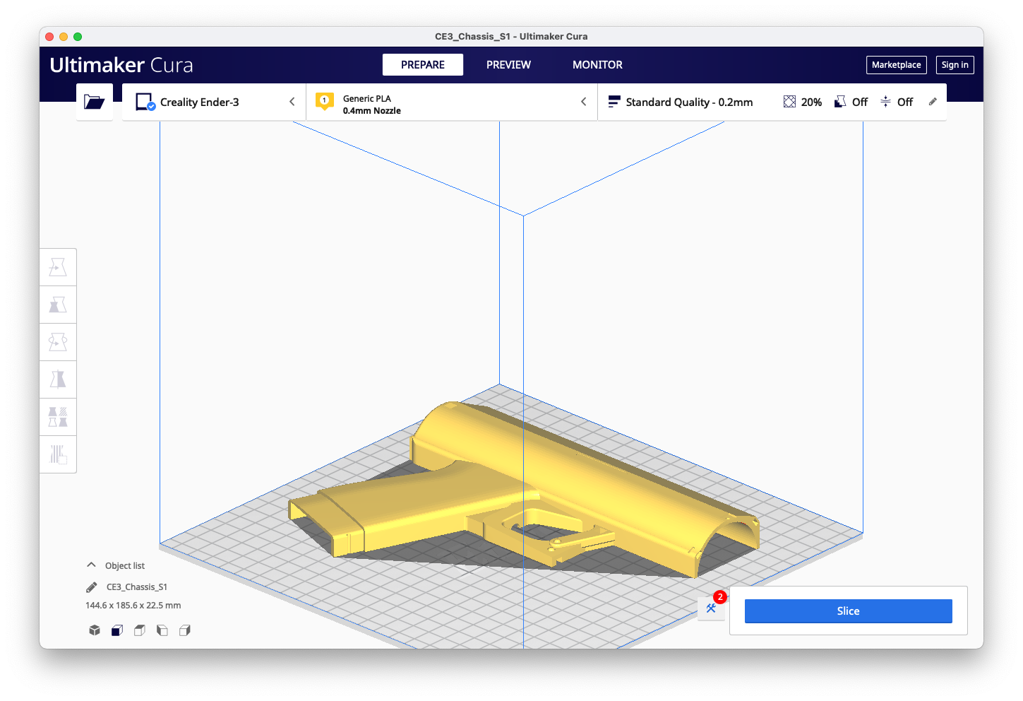
- Chassis S1
- Chassis S2
- Nozzle
- Igniter Box
- Igniter Cage
- Bottom
- N20 Arm/Horn
- Top Cover
- Butane Disc
All of the parts can be printed without supports in PLA at 0.2mm resolution. You may want to. add supports depending on your printer's overhang capability. All parts fit on an ender 3 printbed. Mine is 235x235 but all the parts should fit on a 220mm printbed.
Note the orientation of the following parts. You may print multiple parts t once depending on your printer's volume. Mind your retraction settings and beware of stringing if you choose to do so.
| Chassis S1 | Chassis S2 |
|---|---|
 |
 |
| Nozzle | Bottom |
|---|---|
 |
 |
| Box | Cage |
|---|---|
 |
 |
| Disc | Horn |
|---|---|
 |
 |
| Top | Bottom |
|---|---|
 |
|
Prepare your electronic components and refer to this Wiring Diagram as you lay the motor, battery, LEDs, switch, and button in the chassis.

Disassemble your snake arc lighter and solder extension wires from the factory button to your new trigger button. Then feed the entire board through the hole for the igniter snake and run the button wires up through the hole in the ignitor box along with the LED wires. Clearly mark your wires so you can distinguish between the LEDs which should connect to the switch and the igniter button that should connect to the trigger button.
Optional: You may remove the factory battery and add a buck converter to use the 9v battery's power. I chose to keep the systems separate and preserved the rechargeable battery.

Lay the switch, motor horn assembly, battery, and button in place in the chassis.

Solder your led row and set it in the ignition box running the wires out through the hole. Make sure they are labeled so you don't confuse them with the ignitor button wires. Add an optional piece of electrical tape or insulation over the exposed LED leads. ![]
Next Glue or epoxy the ignition box to the first side of the chassis matching up the notches. Make sure to check your wiring before doing so and run them into the chassis.
Working on a better option than epoxy/glue. Don't want to use metal fasteners. You could potentially zip tie it all together but that proved flimsy in testing. ![]
Close the shell and run zipties through the slots.
Cut the ends off of the ends of matching zipties to act as "nuts" to the ziptie "bolts". The ziptie heads will sit inside the notches on the other side. Pull the zipties tight with pliers and use a twisting motion to fasten tightly. Cut the excess off the zipties. You could drill out the ziptie holes and use screws. Not sure what size or length.
 I like zipties!
Lastly, add the bottom piece and fasten with a piece of filament or a paperclip through the hole. Glue or affix the top cover with double-sided tape over the motor wires to protect them. I prefer tape or velcro as you may want to switch the polarity of the motor by swapping the wires. ![]
Proceed to the safety and usage step of the wiki.