Repository navigation
OvoEasy Assembly Guide
OvoEasy Incubation Unit Construction Procedure |
The OvoEasy incubator framework, designed by Brian Trevelline & John Sanders, is “for axenically-raising oviparous vertebrates for experimental microbiome studies”. This document serves as a procedural framework for the construction process of the OvoEasy incubation units. |
Table of Contents |
|
The OvoEasy incubation units are designed to have a construction process that utilizes affordable 3D printed modules, as well as standardized hardware & components. Each incubation unit has the capability of being networked together & controlled through a central browser access point. The following serves as a table of contents for each unit & module in its construction. |
|
Box Preparation Known Issues/Concerns |
Box Preparation | |
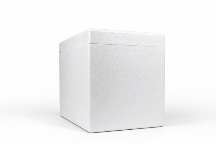
Be aware that heating Styrofoam can & will release toxic fumes, so please try to remain under a hood. Most of the preparation work is to prepare the Styrofoam boxes that the custom PCB board & 3D printed parts will be installed into. | |
General Parts List | |
|
Styrofoam Box (20″ × 13 ¼″ × 15 ⅝″) Heat Wand 3D Printed Template Frame Tile Something to prop the frame and tile onto | |
|
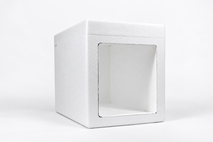
Place the Styrofoam box into the hood, ensuring that the lid of the box is on top, & ensure that the heat wand is plugged in. Note: We used test tube racks/holders to provide a little more room to align the template frame for tracing the guideline & the tile when cutting. |
|
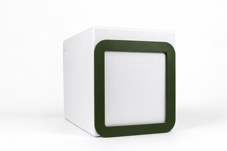
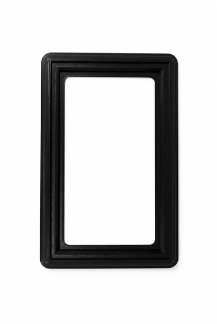
Place the 3D printed template frame aligned with the bottom of the box & centered with the sides, ensuring that the template is taller than it is wide. |
|
|
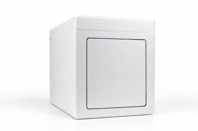
Using a Sharpie or similar marker, trace the inside of the template onto the box, creating a guideline to cut. Note: Try to keep the line thinner, it will help. |
|
|
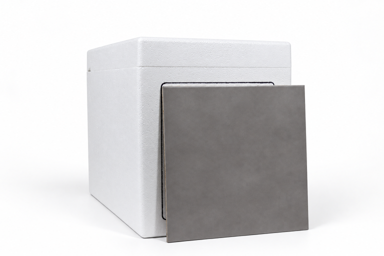
Align the tile with the side of the guideline that supports your dominate hand. Note: The boxes are tapered, meaning you will have to pay attention to ensure that the tile is fully aligned with the guideline. Once in place, push the tile into the box to ensure that it remains in place. |
|
|
Heat the wand by holding in the trigger, ensuring that let it heat for at least 10 seconds (or until the wand is smoking) &, using the tile as a physical guide, begin the cut. Note: How hot the wand is what determines how quickly you’re going to make the cut, so it is important to ensure that it is hot enough. You MUST keep your hand as still as possible, while also ensuring that you keep your hand straight! |
|
Once one side is cut, flip the box & cut the line aligned with your dominate hand; rinse & repeat until all sides are complete. | - |
For the corners, cut diagonally into the box and drag the wand into the cutout Styrofoam, NOT into the box itself! Then, clean the edges up as best as you can. | - |
|
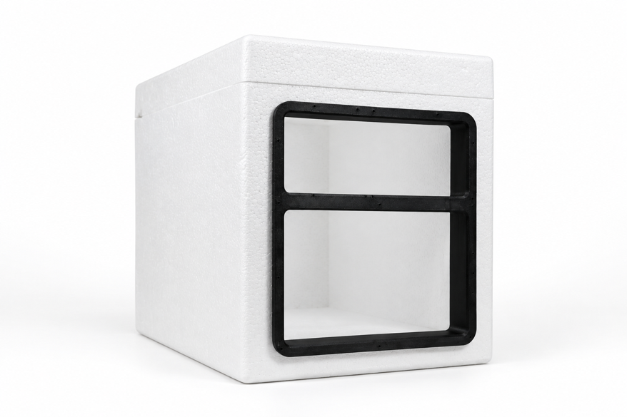
Finally, test fit the 3D printed frame. Note: The frame should have a very tight, cumbersome fit, so don’t be worried you need to use a bit of force. Do NOT remove the frame by the middle or you could break it. |
|
OvoEasy Incubator Framework |
The following is a procedural framework for constructing the core of the OvoEasy incubation unit that accounts for humidity control, networking, power regulation, & the general housing framework. Note that the process utilizes soldering, specific component arrangement, & careful attention to detail. |
Frame & Door Assembly | |
General Parts List | |
Hardware/Components | |
|
13 M3 x 0.5 x 16 mm hexagon socket self-tapping screws 1 xx mm shoulder screw 2 15 mm metal dowel rods 1 30 mm metal dowel rod 1 set of small, metal ball bearings 1 xx mm flanged bushing 2 bushings Foam chord | |
Assembly Pieces | |
|
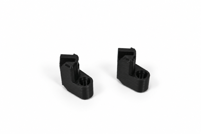
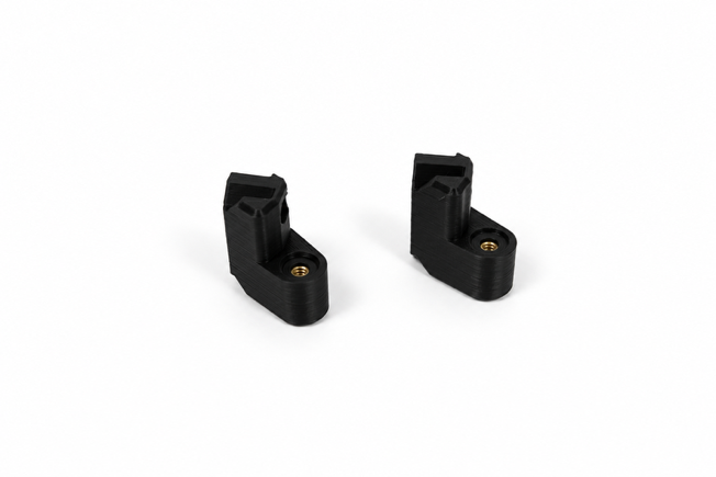
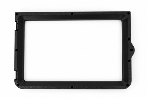
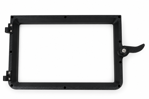
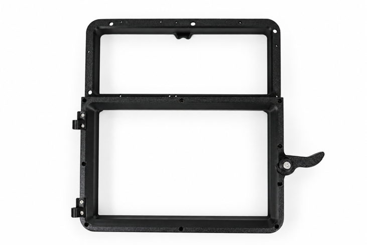
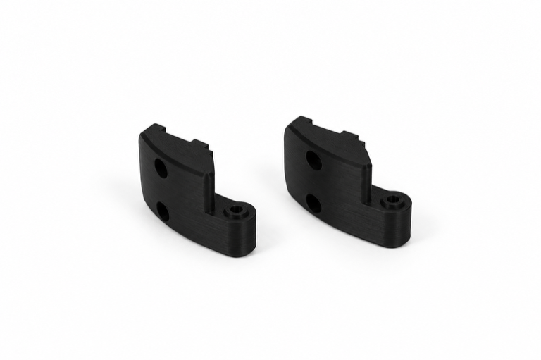
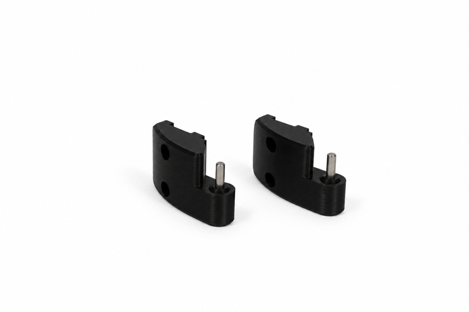
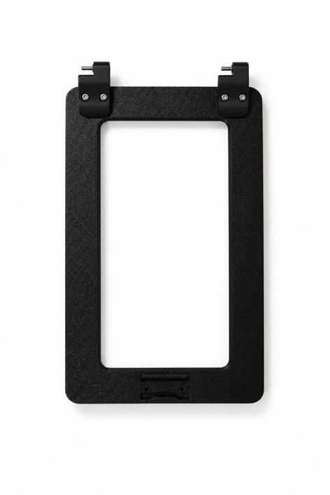
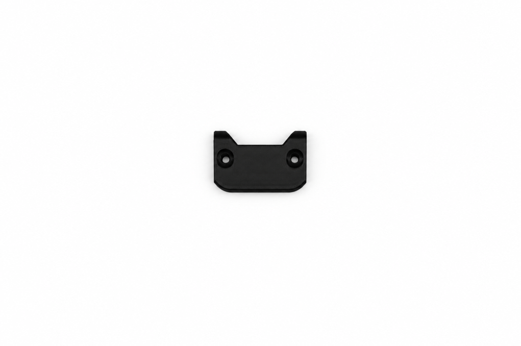
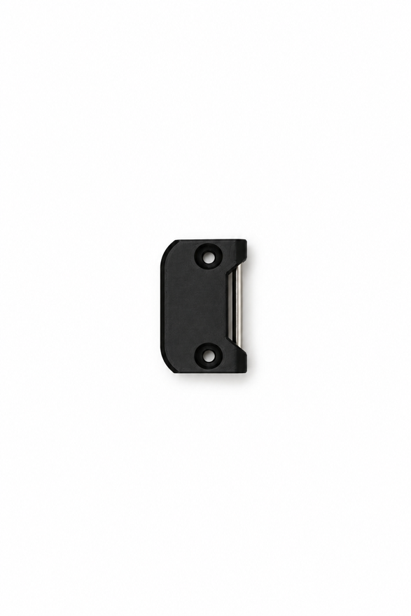
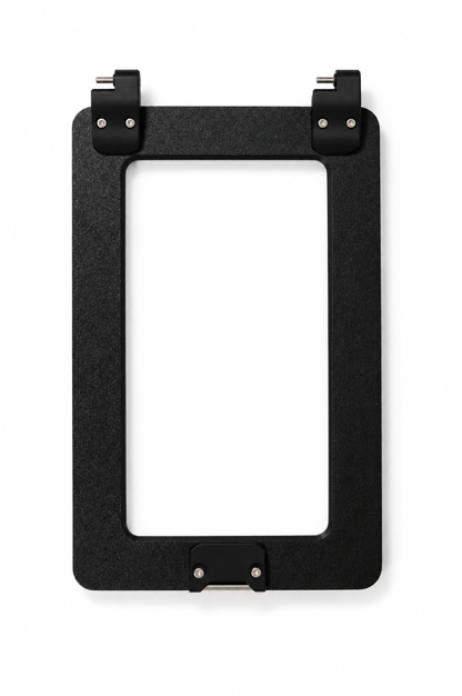
1 frame 2 hinge door pieces (hinge_door) 1 door 2 door frame hinge pieces (hinge_frame) 1 catch 1 latch | |
Frame & Door Frame Assembly | |
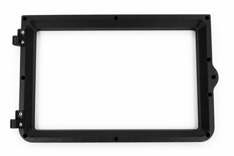
Insert a bushing & an M3 plastic washer into the door frame hinge pieces inserts. |
|
|
On the door frame, insert the 2 hinge-frame pieces into the cutouts & secure them using: 4 M3 x 0.5 x 16 mm hexagon socket screws Note: This should be completed on the left side of the frame. |
|
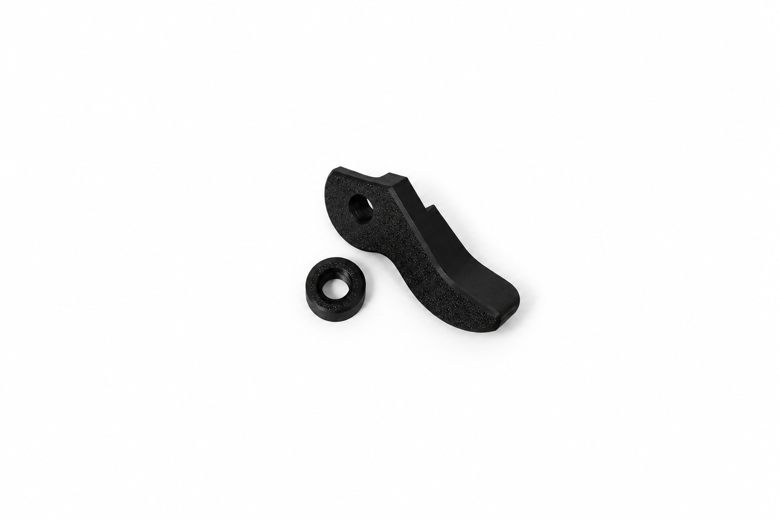
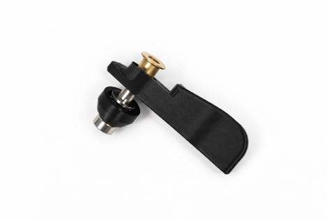
Assemble the latch by first placing the sandwiched barring into the latch cap & then inserting a flanged bushing into the latch itself. |
|
|
Place the latch on the door frame flanged bushing side down, then place the latch cap on the latch aligned with the hole, & then secure using: 1 xx mm shoulder screw |
|
|
Align the door frame to the frame & secure using: 9 M3 x 0.5 x 16 mm hexagon socket head cap self-tapping screws Note: Screw in each of the four corners first. Ensure that the frame is fully screwed in by checking the sides. |
|
Door Assembly | |
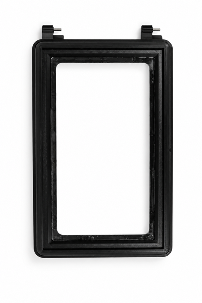
Run foam lining along the interior track of the door. |
|
Add a touch of super glue & insert 1 15 mm metal dowel rod into the each pair of hinge door pieces (hinge_door). |
|
|
Insert the 2 hinge door pieces to the door &, using the cut outs as a guide, secure them to it using: 4 M3 x 0.5 x 16 mm hexagon socket screws |
|
|
Add a touch of super glue into the catch insert & insert 1 30 mm metal dowel rod into the insert. Then, install it into the insert & secure them using: 2 M3 x 0.5 x 16 mm hexagon socket screws Note: This should be on the right side of the door. Use any tool to hammer the dowel into the insert if necessary. |
|
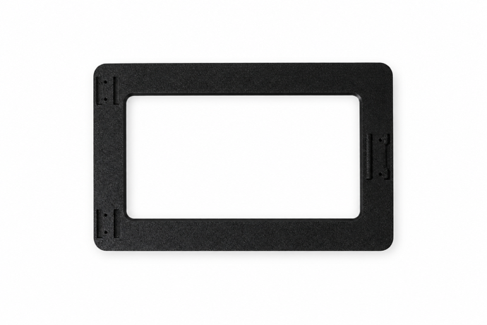
Stick double-sided tape along the inner rim of the door frame’s window, remove the protective cover on the acrylic & then install the acrylic. |
|
Humidity Module Assembly | |
General Parts List | |
Hardware/Components | |
|
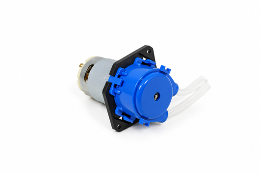
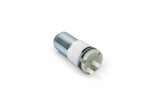
9 M3 x 0.5 x 8 mm hexagon socket screws 3 M3 x 0.5 x 8 mm button head screws 8 stud magnets 3 square nuts 2 19-size rubber bands (3-1/2” x 1/16”) 2 strips of standard wire (~1 ft) 1 plastic cup Foam chord 1 atomizer with water wick 1 IR sensor 1 peristaltic pump 1 vacuum pump | |
Assembly Pieces | |
|
1 vacuum pump cradle (370_carrier_print_OvoEasy Door_carrier) | |
|
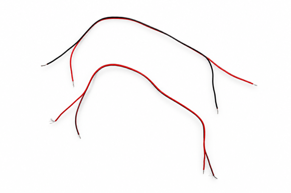
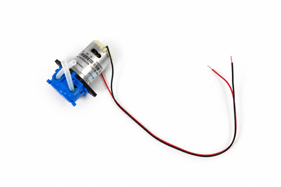
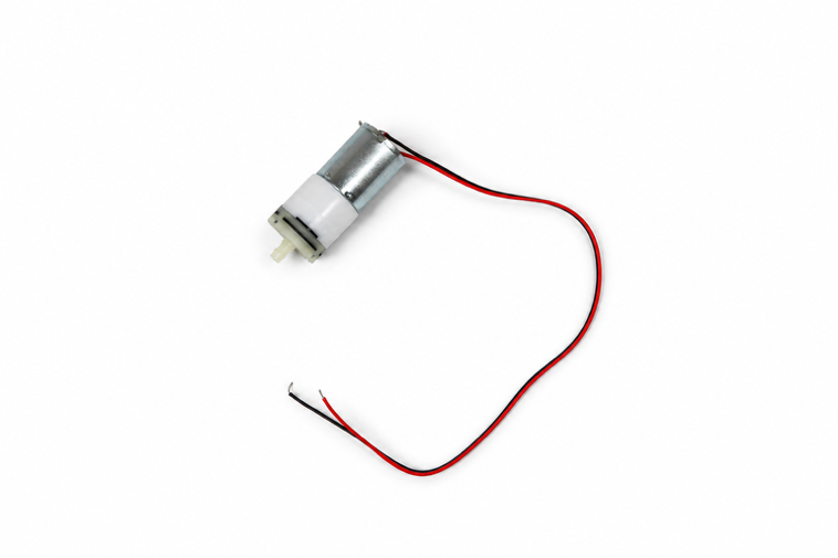
Prepare peristaltic pump & vacuum pump by acquiring a little under a foot of wire for each, separate the two strands on both sides, & then strip them on both sides. Note: Wires should be cut to around ~12 inches. |
|
|
Wrap one side of the exposed wire loosely through the terminals on each pump’s backside & solder the wires to the terminals. |
|
|
Glue 4 stud magnets into hexagonal holes along humidity frame backside. Note: Place one of the stud magnets down to use as a template to determine polarity. Once determined, use an X to mark the template, see which side of the magnet connects to the second & mark the second stud with a dot, then glue the magnet into the insert with the dot facing you. |
|
Glue 4 stud magnets with opposing polarity to the humidity cover into hexagonal holes along humidity frame backside, & then attach the cover. |
|
Line foam chord through humidity frame’s interior track. |
|
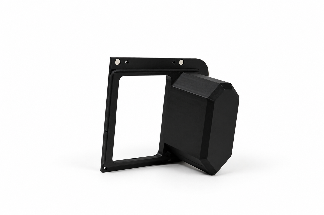
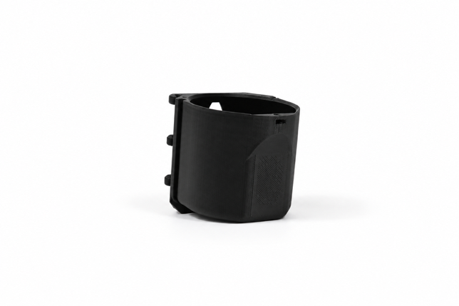
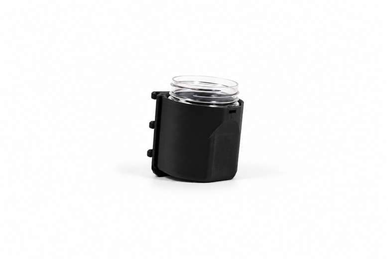
Insert plastic cup into the reservoir carrier. |
|
|
Insert the IR sensor through the right slot of the reservoir lid & secure it from underneath with the hand screw/nut. Note: Keep wires on the left side of the insert. The hand screw is screwed into the sensor already; unscrew it from the sensor & then screw it back in. |
|
|
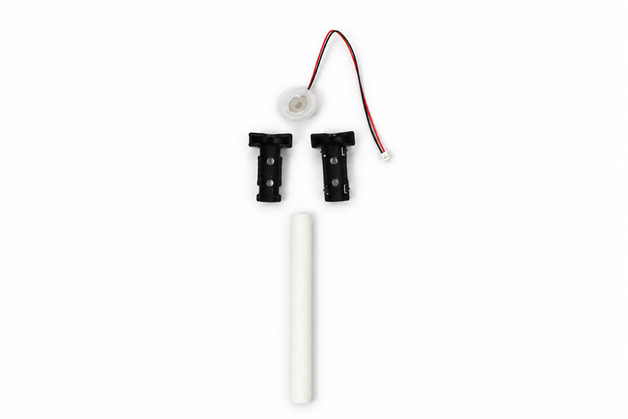
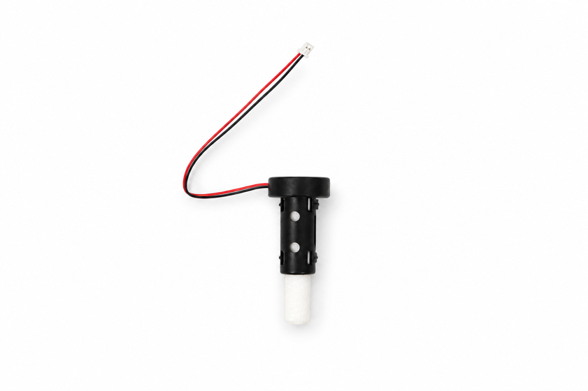
Put together atomizer using pieces in the bag, ensuring that the wire exits through the side of the top, cut the wick down to 50 mm & insert the water wick; Note: Keep wires on the left side of the insert once installed. VERY tight fit don’t be hesitant to use more force than you’d think. Ensure that the wick is inserted into the flat side in. The atomizer itself should be inserted solder side up. |
|
|
Insert the completed atomizer into the slot in the reservoir lid & secure the deflector, ensuring its facing away from the humidity frame. On the face of the reservoir carrier, secure the completed reservoir lid by using: 1 square nut 1 M3 x 0.5 x 8 mm button head screw Note: Use the 2 mm driver head. |
|
|
Run atomizer & sensor wires through the left side of the reservoir lid & then run foam seal through the track around the entire cup module. Note: Keep in mind that the foam seal will hold the wires. |
|
|
Insert the entire reservoir module into the frame, cup-side in, & secure to the frame using: 2 square nuts 2 M3 x 0.5 x 8 mm button head screws Note: Using small cutters, trim the very small stands on the top of the atomizer or else the module will not properly insert into the frame. |
|
|
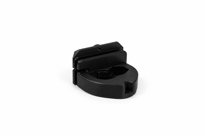
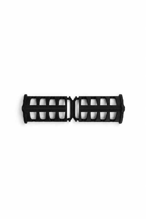
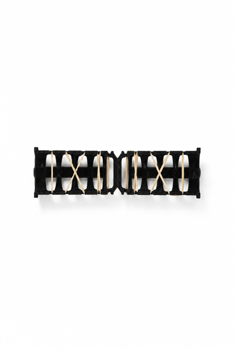
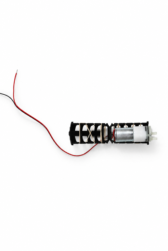
Take the vacuum pump cradle & lace rubber bands along the sides, then push the wire of the vacuum pump itself through the bottom & close. Note: Use 19-size rubber bands (3-1/2” x 1/16”). |
|
|
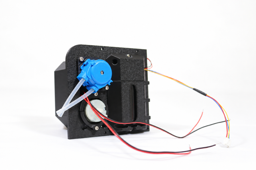
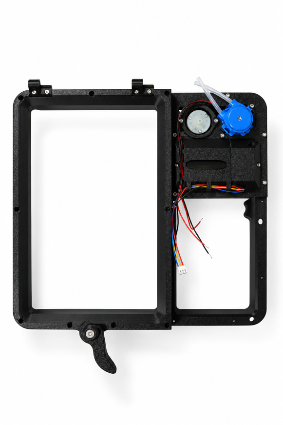
Install the completed vacuum pump cradle & peristaltic pump into the bottom hole & secure using: 4 M3 x 0.5 x 8 mm hexagon socket screws Note: The correct vacuum pump to use has two pins, one black membrane/ring, & runs at 12V. |
|
|
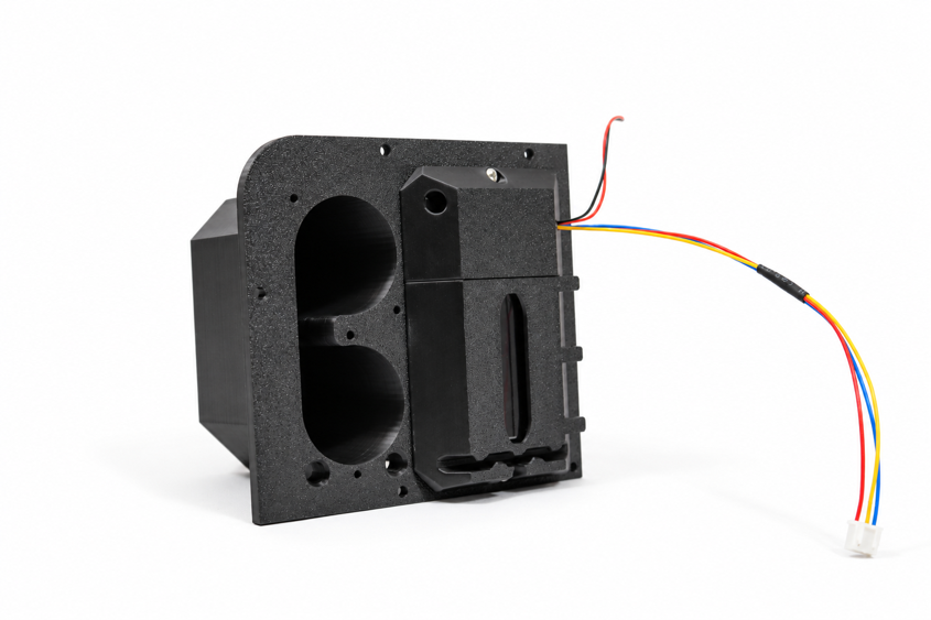
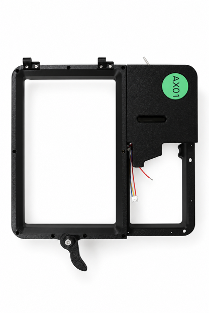
Insert the humidity frame in top left portion of the frame & secure using: 5 M3 x 0.5 x 8 mm hexagon socket head cap screws |
|
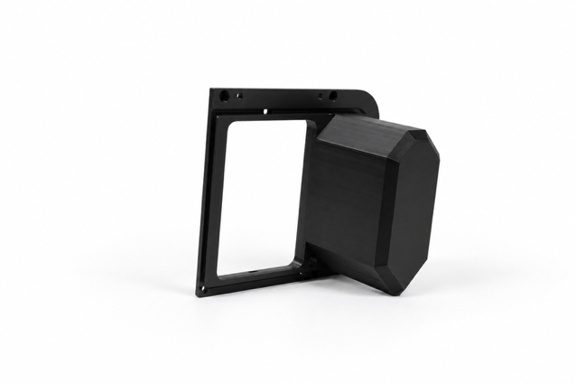
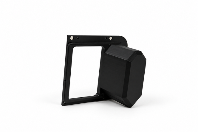
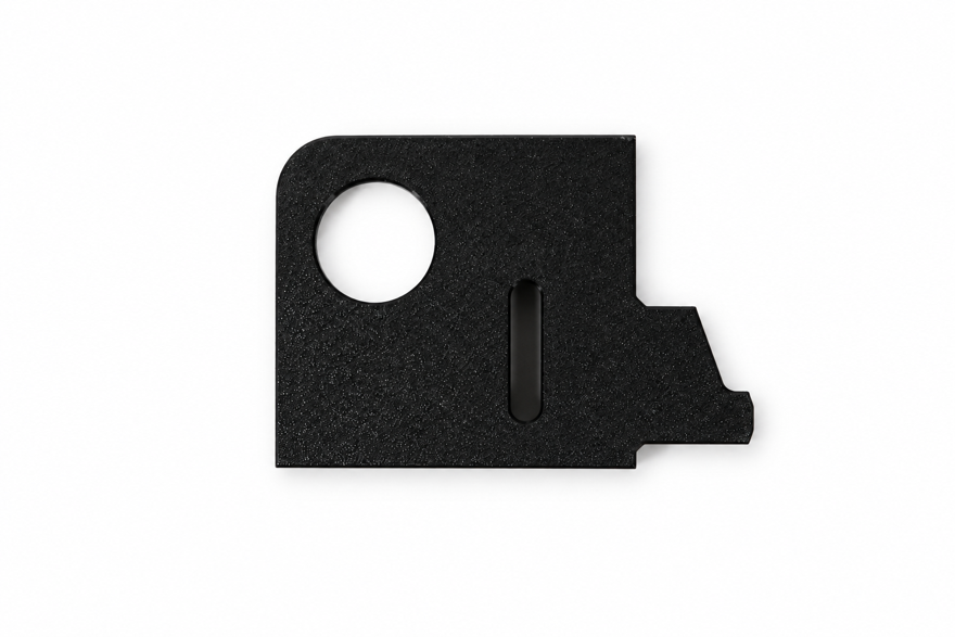
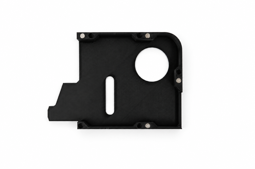
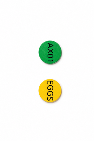
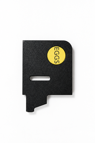
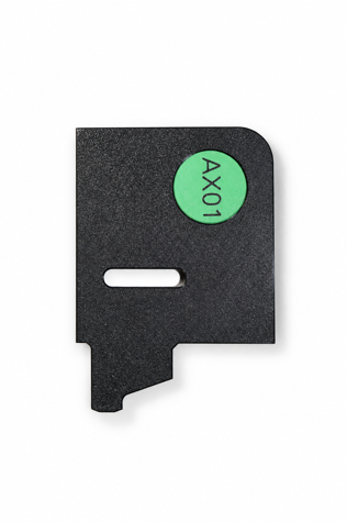
Note that the covers are designed to have a label install for a given treatment group or to distinguish if a unit is for hatchlings or eggs. |
|
Controller Module Assembly | |
General Parts List | |
Hardware/Components | |
|
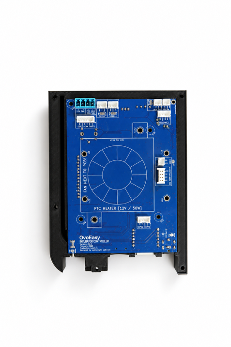
1 custom OvoEasy PCB board 1 screen insert 1 heating unit 10 M3 x 0.5 x 16 mm hexagon socket screws 5 M3 x 0.5 x 8 mm hexagon socket screw 4 3 mm metal dowel rods 1 screw-block terminal 1 atomizer chip 1 AHT45 temperature/humidity sensor chip Foam chord | |
Assembly Pieces | |
|
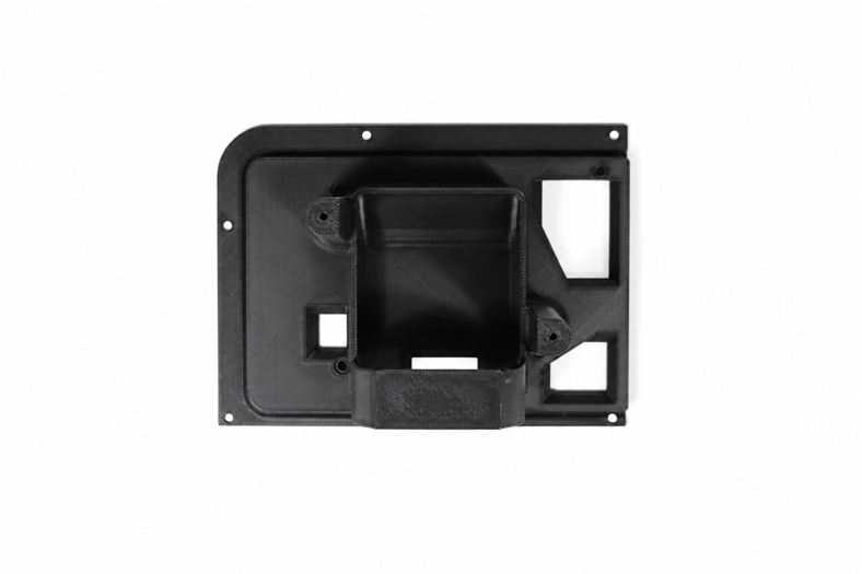
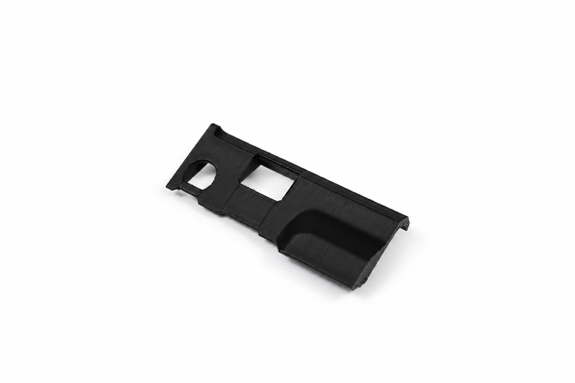
1 I/O cover (main_cover) | |
|
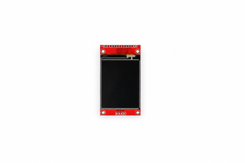
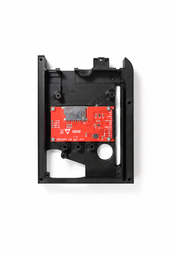
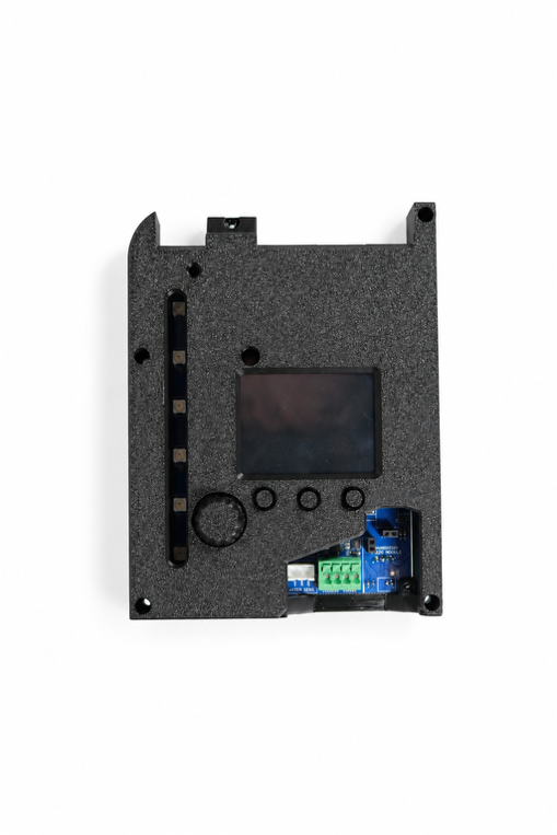
Place the front panel with its backside up, remove the screen protector from the screen & place it into the middle insert with the pins at the top of the panel, secure it into the panel using: 4 M3 x 0.5 x 8 mm hexagon socket screws |
|
|
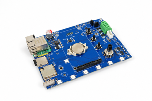
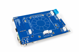
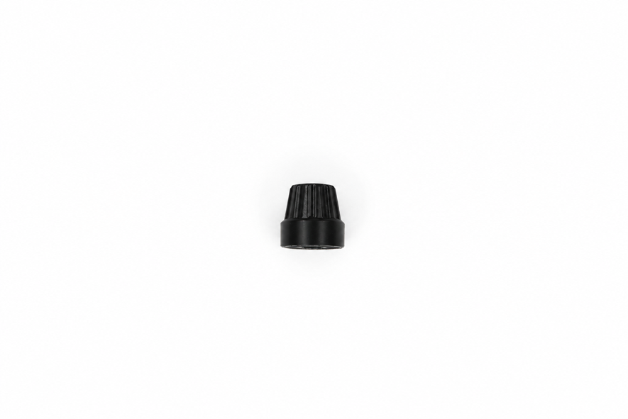
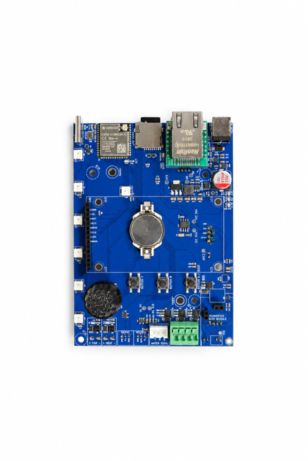
Install the encoder knob onto the OvoEasy PCB board & then carefully align the screen pins into the OvoEasy PCB board. Note: Ensure that the pins for the ethernet port are properly cut or else the back panel cannot be secured properly. |
|
|
Install the back panel & secure it ONLY using the screw holes that are on the PCB itself using: 5 M3 x 0.5 x 16 mm hexagon socket screws Note: To put it another way, do NOT screw into the screw holes on the perimeter/rim as those are used to attach the module to the frame later. |
|
|
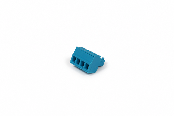
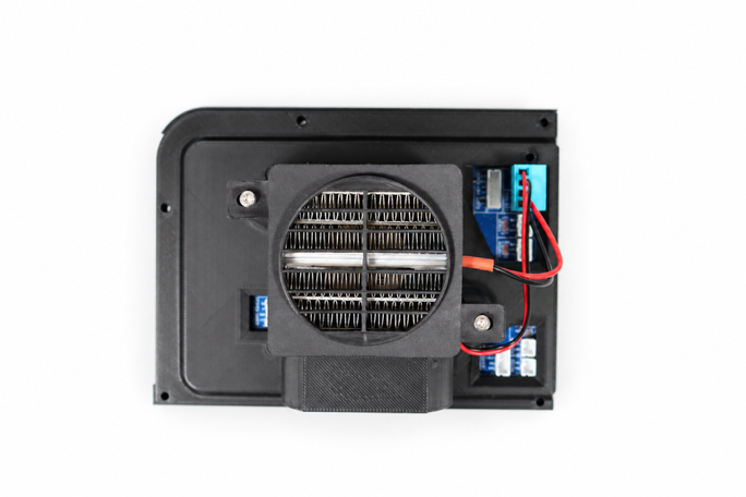
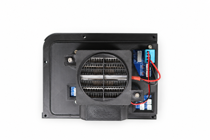
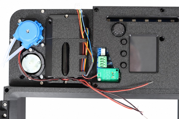
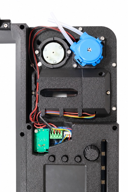
Secure the heater into the middle fixture, ensuring that the wires exit from the side of the module with the ethernet port, using: 2 M3 x 0.5 x 16 mm hexagon socket screws Once complete, use a blue screw terminal block for the heater wires to be installed into & insert it in the appropriate port on the OvoEasy PCB board. Note: The left side of the block is for the fan wires, while the right side of the block is for the heating element. Red is positive on the left, black is negative on the right. Turn the screws to the left to open each terminal. |
|
|
Run foam along the inner rim of the back panel & then install the module into the frame, securing it using: 5 M3 x 0.5 x 16 mm hexagon socket screws |
|
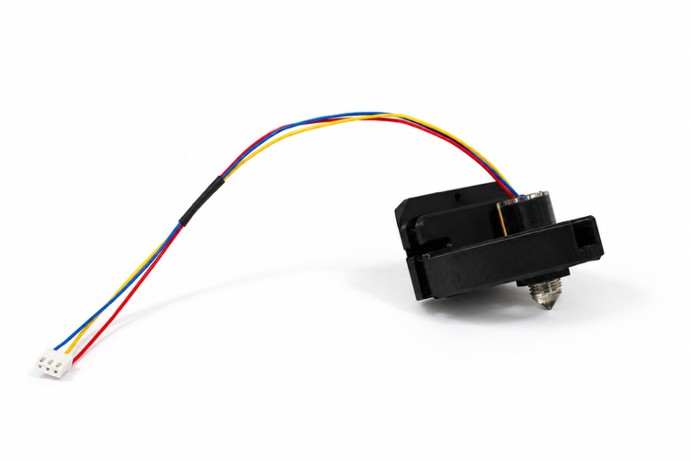
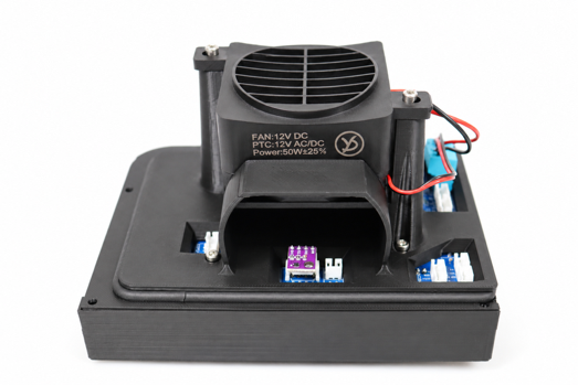
Install the AHT45 temperature/humidity chip just under the heater’s output ramp. |
|
|
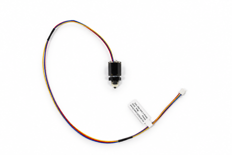
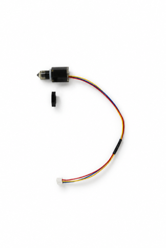
Install the atomizer chip by inserting the appropriate wire from the main PCB board to the port on the atomizer chip, then aligning the pins on the chip to the port on the main PCB board. Note: There are two ports for this on the main PCB board to ensure full compatibility between the atomizers that can be used. By prepared, that means trimming a connector & soldering it to the chip. |
|
|
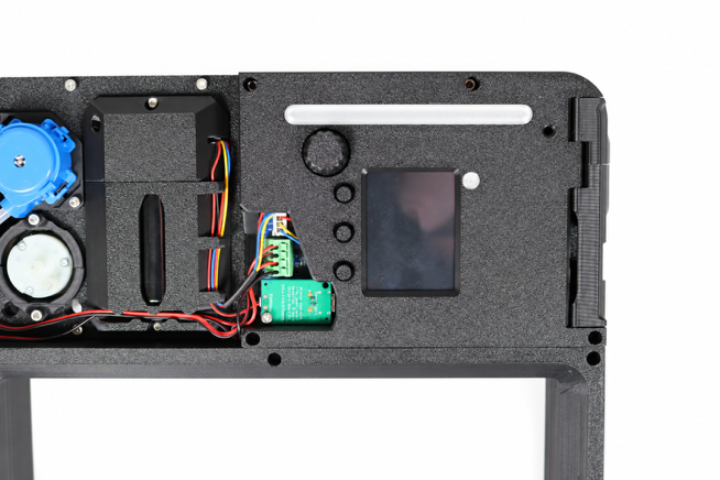
Install the peristaltic & vacuum pump wires into the appropriate green PCB terminal block terminals. Note: Double check that the appropriate wires are being installed into the correct terminals. The right side is for the peristaltic pump, labeled as “WATER”, while the left is for the vacuum pump, labeled as “VACUUM”. |
|
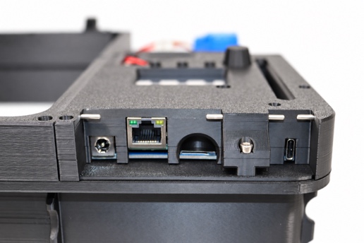
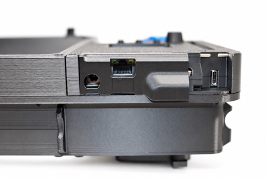
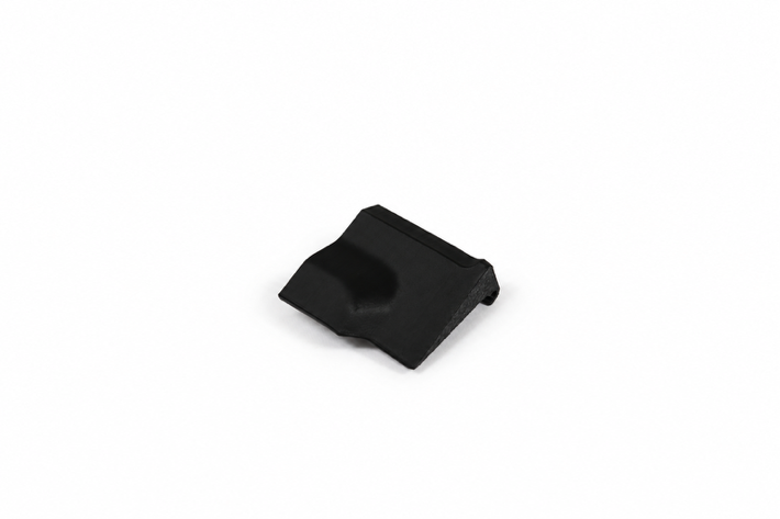
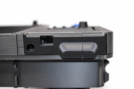
Install the I/O cover on the right side of the module by inserting 2 3 mm metal dowel rods into the holes on either side, then place the cover onto them, which will act as a hinge. |
|
Install the USB cover directly above by inserting 2 3 mm metal dowel rods into the holes on either side, & then place the cover onto them. |
|
To install the acrylic light covers, apply a small bit of super glue into the two slots on the face of the controller module & then insert the acrylic covers. |
|
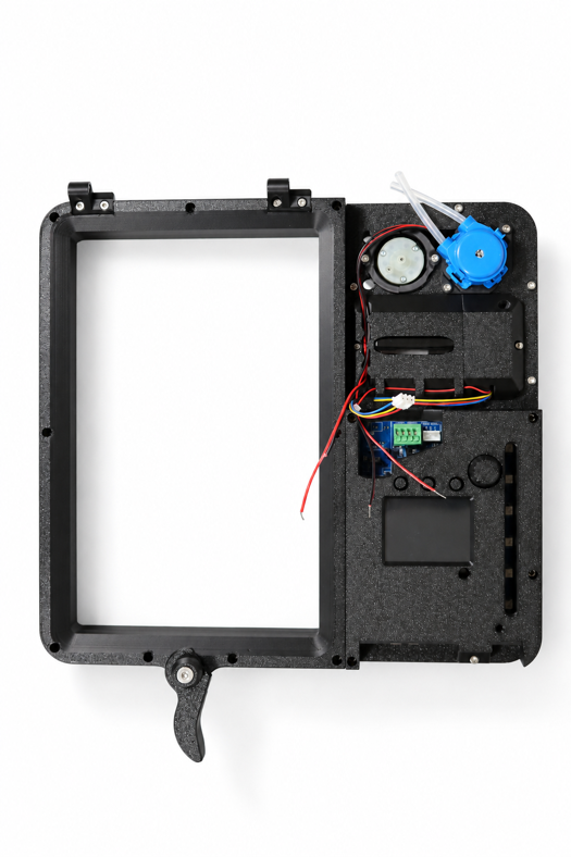
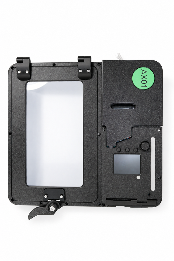
You have now completed the construction of an OvoEasy incubator! |
|
Known Issues/Problems |
|
Hinge design requires friction fitting; may require glue to secure dowel rods. When securing humidity module with 3M 8 mm, can strip very easily so be careful. Use 3M 16 mm if the fittings strip. Possibly supplement with 10 or 12 mm. Could still use 8 mms, go in at an angle & then twist back. Ensure that we’re using the correct atomizer. WRONG atomizer features Chinese characters. Ensure that we’re using the correct vacuum pumps; they feature two prongs on the top, one black rim/membrane, & run at 12V. |