Hardware assembly
As described in the hardware description and BOM, you are free to choose which components to install. There are recommended configurations but these are guidelines, not rules.
Build on a breadboard first, then move to a permanent solution.

LCD
Connected to VSPI (MOSI=23, MISO=19, CLK=18, CS=5)
| ESP32 | LCD |
|---|---|
| +3.3V | BLA (backlight anode - can also be +5V) |
| GND | BLK |
| 4 | RST |
| GND | PSB |
| +5V | VCC (try 3.3V first; my LCD requires 5V) |
| GND | GND |
| 5 | RS |
| 18 | E |
| 23 | R/W |
Encoder
| ESP32 | Encoder |
|---|---|
| +3.3V | 5V/VCC |
| GND | GND |
| 32 | Key |
| 34 | S2 |
| 35 | S1 |
MAX31855
Connected to HSPI (MOSI=13, MISO=12, CLK=14). Add a 10-100nF capacitor across the thermocouple input pins on each board.
| ESP32 | MAX31855 A (primary) |
|---|---|
| +3.3V | VCC |
| GND | GND |
| 12 | SO/DO |
| 14 | SCK |
| 27 | CS |
| ESP32 | MAX31855 B (optional, housing temp) |
|---|---|
| +3.3V | VCC |
| GND | GND |
| 12 | SO/DO |
| 14 | SCK |
| 15 | CS |
Relays
| ESP32 | SSR |
|---|---|
| GND | GND |
| 19** | IN |
| ESP32 | EMR (SLA-05VDC-SL-C) |
|---|---|
| GND | GND |
| 21 | IN |
| 5-48V* | VCC |
(*) Use an external 5V supply - do not use 5V from the ESP32 board. Any 5V-48V supply with ~1W capacity works.
(**) For a second SSR (fires simultaneously with the first), use GPIO 22 - uncomment SSR2_RELAY_PIN in ESP32Kiln.h.
Power meter
| ESP | 30A/1V sensor |
|---|---|
| 3.3V | 3.3V |
| GND | GND |
| 33 | outermost mini jack pin |
Alarm
ALARM_PIN goes HIGH on program abort (error or user-triggered). Connect to a buzzer or relay to signal failure.
| ESP | Relay/Buzzer |
|---|---|
| GND | GND |
| 26 | +3.3V |
This is the minimum fully functional configuration to control a heating device.
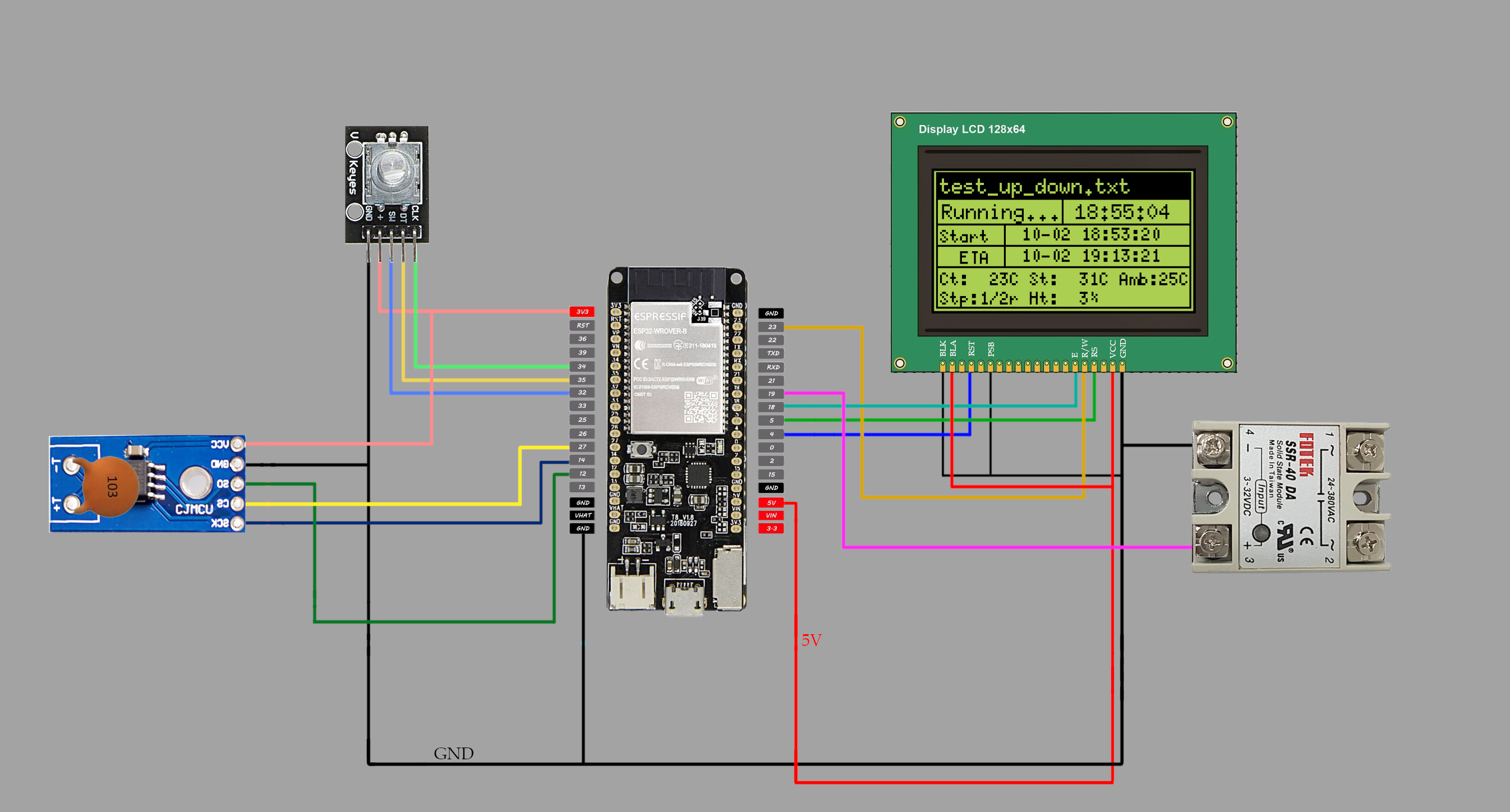
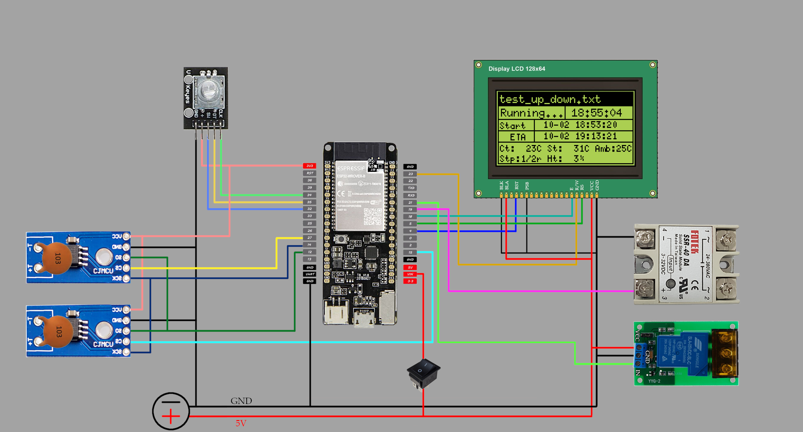
Full configuration with all components.
If you have a voltage-output sensor (+/-1V), you need two 10kOhm resistors and a 10uF capacitor. Connect the first and third pins of the micro jack.

The voltage divider shifts the -1V to +1V AC signal up to approximately 0.65V to 2.65V, which is within the ESP32 ADC's 0-3.3V range. The capacitor adds a small amount of hysteresis.
Use a regulated +5V supply. Power the ESP32 through VIN (do not connect VIN and USB simultaneously), the EMR relay (~185mA), and LCD backlight from the same supply.
Powering from USB alone is often insufficient: many boards have weak 5V output on the VIN/5V pin when powered by USB, and cannot drive the EMR relay and LCD at the same time.
If you use a remote relay box with long cable runs, account for voltage drop. A 1.5m cable with 0.35mm² wires can drop 3.3V down to ~2.75V at the far end. Most SSRs will still trigger reliably above 2V, but keep runs short and wires thick for reliability.