How e‐Paper works and how to work with it
e-Paper is the agreed upon name to describe various types of electrophoretic displays (EPDs) - displays composed of arrays of colored particles suspended in clear oil which are manipulated with electric fields. The company famous for commercializing this technology is Eink. They have trademarked the name for their company and the EPDs they sell. Other companies sell similar products, but must use the term e-Paper instead of Eink.
As a display type, e-Paper is unique. It presents some serious challenges (slow updates, reflective only), and some amazing benefits (high contrast, wide viewing angles and no energy needed to retain the image). Because of it's unique properties, the software (your software) which drives it also needs to be different from more common display software. There are two main types of interfaces to EPDs: serial and parallel. The serial type have a built-in, low power microcontroller with its own memory. These are controlled by sending single byte commands and image pixel data. The commands trigger the on-glass MCU to redraw the display with the contents of the internal memory. The parallel panels (usually found in e-book readers) have a simpler digital state machine inside them and only contain memory for a single row of the display. They require the external MPU to control all aspects of updating the display.
EPDs are composed of arrays of tiny vertical cells of clear oil with small colored grains holding a static charge (one color is positively charged, the other negatively) suspended in them. The top of each cell (viewing side) has a transparent electrode and the bottom has a semi-transparent electrode. These 2 electrodes are connected to a strong positive and negative voltage source (15 to 28 Volts) controlled by a pair of transistors. When a voltage is applied to either side, the pigment grains with the opposite polarity move towards that side and the grains with the same polarity are repelled and move towards the other side. Changing the contents of the display requires 'pushing' the charged particles one way or the other to get the desired color. It takes a finite amount of time for the particles to move through the oil and they move slower in colder temperatures. You've probably seen e-Paper displays update with a pulsating or flashing between black and white. This is needed to ensure the known state of each pixel before pushing it towards the desired color. The continuous movement also makes use of inertia to get the particles moved fully into their final positions. Care must also be taken to not push the particles more towards one color versus the other or a static charge can accumulate and cause the display to misbehave. The industry term for this is the "balance of charge". Unbalanced pushes can cause the particles to move to the wrong color after power is removed; this can look like a 'graying' of the display after an update. Pushing the pixels many times between fully black and white can clear this charge if needed. In other words, a charge imbalance is usually not a fatal situation for the display.
The first versions of e-Paper were only able to display black and white. Each cell had black and white colored particles which would change places (top/bottom) to change the visible color. Later models introduced red particles. The red particles were lighter and had a lower charge so that updates occurred in two steps: first, the heavier black and white particles were moved, followed by the lighter red particles. These were soon followed by 4-color panels which paired black/white and red/yellow. Newer panels added a third pair of colors to allow 6 at a time (Spectra6). The addition of more color pairs increased the time to update the display since each pair must be controlled independently of the others. Update times for the 6-color panels are usually 25-35 seconds. Another multi-color idea was created called Kaleido. This makes use of a precisely placed color filter array (CFA) similar to those used in LCD displays. The position of the black/white pixels under the color filter allows for a wider range of colors. Use of a CFA allows for fast updates since the underlying panel is only black/white. One downside to the CFA panels is that the colors are darker and low saturation because another layer has been added between the light source and your eyes. You'll see specifications for these panels show something like "300dpi in b/w mode and 100dpi in color mode". The reason is that the R/G/B groupings require 3 b/w pixels to form a single color pixel. If pixels are arranged to show groups of a pure color, your eyes will see color, but if the pixels ignore the CFA positions, the mixing of the individual colors will look like shades of gray.
There are 2 main vendors of SPI ePaper controllers - UltraChip and Solomon Systech. A third vendor, Jadard, focuses just on 4 and 6-color EPDs and their chips behave a lot like the ones from UltraChip. All of these different controllers do essentially the same job, but with slightly different commands and parameters. Care must be taken to ensure you're using the correct command set and parameters; wrong values can fry the EPD's power circuit. Choosing the wrong controller type can accidentally send commands which fry the panel too. The majority of these SPI panels use the same 24-pin connector; a rare standard shared by many different vendors. There are 24 pins because the DC-DC boost circuit, which allows the EPD to generate the positive and negative high voltages, is provided by you (it's not part of the panel). If it were integrated with the controller on the glass, it would make the panels thicker due to the inductor coil. This DC-DC boost circuit allows the 3.3V you supply to drive the panel's high voltage needs. Here is an open source circuit board that implements this external DC-DC boost circuit. This particular board was designed by my friend Martin and is meant to simplify using SPI EPDs with any MCU you might own.
These are the steps needed to change the contents of an EPD with a serial controller:
- Wake up the e-paper controller from deep sleep (toggle the RESET signal)
- Send a sequence of commands to initialize the controller (specific to the panel and controller type; settings like the display size and power values)
- Send the pixels to the internal framebuffer(s) of the controller (from your local copy or generated on the fly)
- Tell the controller the type of update to do (optionally send a lookup table or use a built-in one)
- Tell the controller to run the update sequence
- Wait for the controller to finish the update (monitor the BUSY signal)
- Send the command to disable the power circuit and then send the sleep command to save power.
All of the above steps are quite specific to each controller type and panel. Sending a wrong value could fry your expensive display!
I wrote the bb_epaper library to reduce the frustration of working with these displays. Many EPD details are simplified with my API, while still supporting all of the functions of each panel. For example, the controller type and its specific commands are abstracted into a panel enumeration with logical names. Here is a minimal "hello world" program to demonstrate what I mean. In the example below, the EPD42_400x300 enumerated value signifies a 4.2" B/W panel that's got 400 pixels horizontally and 300 rows vertically.
void main() {
 BBEPAPER bbep(EPD42_400x300); // instantiate the class with the panel type<br>
 bbep.initIO(PIN_DC, PIN_RST, PIN_BUSY, PIN_CS, MOSI, SCK, 4000000); // tell the library how the panel is connected<br>
 // The bb_epaper library functions automatically wake up the panel if it was in a sleeping state<br>
 bbep.fillScreen(BBEP_WHITE); // fill the display memory with white (no local copy of graphics)<br>
 bbep.setFont(FONT_16x16); // use the internal 16x16 font<br>
 bbep.setTextColor(BBEP_BLACK);<br>
 bbep.setCursor(0,0); // start at the top left of the display (native orientation)<br>
 bbep.println("Hello World"); // use the println() method to draw the text directly into the e-paper's framebuffer memory<br>
 bbep.refresh(REFRESH_FULL, true); // do a full refresh and wait for BUSY to go idle<br>
 bbep.sleep(LIGHT_SLEEP); // put the panel into light sleep mode (framebuffer RAM contents are retained)<br>
}
The easiest way to get started is to utilize one of the many example projects I've written for Arduino and Linux. Simply modify the panel type and GPIO connections to match your setup and you're ready to go. Use my panel selection guide to help you choose the right panel name.
The framebuffer inside the EPD controller consists of two planes of 1 bit per pixel static RAM. The memory layout/rotation can be changed with a configuration command. bb_epaper normally configures it as row-major order, MSB on the left. This means that the upper left pixel of the display is bit 7 (0x80) of the first byte of memory and that the bytes are oriented horizontally so that pixel 7,0 is bit 0 (0x01) of the first byte. These two planes of memory can be used for differential (aka partial) updates - only pushing on pixels which change when comparing the 'old' memory plane with the 'new'. They can also be used to form a 2-bit grayscale mode (4 unique colors). On the bb_epaper side, you can allocate one or two planes for working with both B/W and 3/4 color e-Paper displays. bb_epaper allows you to directly access and modify this memory, or use the built-in font and 2D graphics primitives to draw on it.
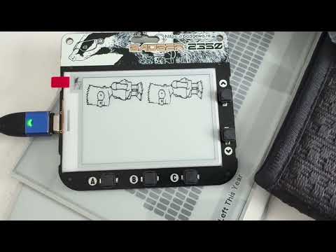
E-paper displays have a lot of complex physics happening under the covers. The process of changing the pixel color takes time and multiple passes. The mobility of the granules in the oil is also changed depending on the temperature and if they are in motion or at rest. Each pulse of the electric field pushes the granules on their path, but doesn't push them fully. They must be given multiple pushes to get to their extreme positions of maximum white or black. The 'full refresh' mode uses multiple passes of sending all of the pixels to their extreme white and black positions to increase their mobility in the oil, then the final step sets them to the color that you've chosen. The 'fast' version of this is available as a built-in feature on some displays. It's just an alternate LUT (look up table) of timings which reduces the number of full color swings. Finally, the 'partial' or differential refresh is where the old pixels are compared to the new pixels and electric charges are only applied to the pixels which changed color; all other pixels are left in their current state. They are given a shorter push in the direction of the new color without the full black/white flash. This results in updates that are much faster and less visually jarring. The compromise is that the pixels don't always reach their fully seated positions and 'ghosting' can appear after each update. Ghosting is the term used to describe pixels which haven't fully reached their desired colors, so you can see a hint of the previous image. It is recommended to do full updates after 10 or so partial updates to get the colors back to full contrast. The normal way to use the partial update feature is the have a 1-bit memory plane representing the old pixels and a 1-bit memory plane representing the new pixels. The average times for these different types of refreshes on black and white e-paper displays is usually on the order of 2.5 seconds for full refresh, 1.5 seconds for fast refresh and 300-600 milliseconds for partial refresh. The following video demonstrates the differences between full, fast and partial updates running on a Pimoroni Badger2350 (2.66" 176x264 black/white SPI panel). The video sequence is a full update followed by multiple partial updates and lastly, a fast update:
My FOSS work with ePaper (bb_epaper and FastEPD) is primarily aimed at making a difficult technology simpler. I can only do so much on the software side, some challenges exist because the EPD vendors don't make it easy for us. Here are some tips to help you avoid pulling your hair out:
- Q: I set everything up correctly, but the panel doesn't update, what's going on?
A: There are many similar looking panels which are sold with both the UC and SS controllers AND variants of those controllers. Ensure you're using the correct settings for your specific panel. - Q: The panel is updating, but I'm seeing 'snow' instead of the correct image.
A: Normal usage of bb_epaper keeps a copy of the pixels in your MCU/MPU memory and you must explicitly write them to the EPD before starting an update. - Q: I put the EPD to sleep, but it's still drawing 2mA, why?
A: The RESET line needs to be pulled up either by a fixed resistor or the GPIO controlling it. If left in tri-state, the EPD will wake up and draw 1-2mA while sitting idle. - Q: I'm working with a black/white/red panel and the whole display is red after every update?
A: The red plane is typically inverted and has priority over the B/W plane, so it must be written as 0's where you don't want red pixels. - Q: Can I play fast animations on ePaper?
A: The panels are capable of relatively fast updates, but the built-in LUTs and the 1-bit (serial) data interface prevent getting the maximum speed possible. 300-600ms per partial update is a realistic limit. - Q: When I put the EPD to sleep, the pixels become gray and splotchy over the next few seconds, why?
A: This graying indicates that you're not keeping the "balance of charge" and your panel has accumulated a residual static charge. You will need many balanced black/white clears to fix it.
- Q: How much should I expect to pay for my EPD?<>A: Prices vary widely by panel type, vendor and popularity. B/W panels are generally cheaper than multi-color and small panels are less than large. Companies like Seeed Studios and Elecrow sell individual panels for less than most other vendors and will also give you a quantity discount if you ask. As an example, the very popular 2.9" 128x296 B/W panels can be bought for as little as $4 each.
Parallel EPDs have the same type of pixels as serial displays, but they connect to the MCU/MPU with a high speed parallel (8 or 16-bit) interface and have no controller built in. The operation of these displays is kept secret by Eink (NDA required), but some clever engineers were able to reverse engineer them a few years ago. They are sold for applications where speed is more important than power usage. Pixels are changed by sending rows of control bytes (2 bits for each pixel). The time that each row is active determines how far the grains travel on their path towards black or white. A slow computer driving the data will have less control over updates since each pass of 'pushes' will have a much stronger effect. The industry uses the term 'waveform' to describe digital tables of push patterns to accomplish gray levels somewhere between black and white. I dislike using this term because there is no waveform, not digital nor analog. Instead, the pattern tables just have a list of black/white/skip (01, 10, 00) instructions to accomplish each gray shade.
These are the steps needed to change the contents of an EPD with a parallel controller:
- Turn on the power boost circuit (usually controlled by a TI TPS65185)
- Convert the new image into a series of 'push' data (2-bits per pixel, the B/W transistor activation codes)
- Send each row's data to the panel's row buffer and step through all rows by toggling the row counter circuit
- Repeat the frame update as many times as needed to completely push the pixels into their final positions
- Turn off the power boost circuit
Here is a minimal "hello world" program which does all of the above:
FASTEPD epd;
void main() {
 epd.initPanel(BB_PANEL_M5PAPERS3); // instantiate the class with the panel type<br>
 epd.fillScreen(BBEP_WHITE); // fill the display memory with white (local copy of graphics)<br>
 epd.setFont(FONT_16x16); // use the internal 16x16 font<br>
 epd.setTextColor(BBEP_BLACK);<br>
 epd.setCursor(0,0); // start at the top left of the display (native orientation)<br>
 epd.println("Hello World");<br>
 epd.fullrefresh(); // Do a full refresh (full wipe black/white before content is drawn)<br>
}
Again, I've written numerous examples to get you started and each demonstrates a different set of functionality.
Why create custom LUTs?
- The panel you bought comes with limited built-in update options (e.g. full refresh only)
- You want faster updates
- You need to add more refinements (e.g. more gray levels)
- You have a unique project that needs something not offered by the existing LUTs
What's in a LUT?
A LUT contains 4 (or 5 if VCOM can be controlled) groups of numbers representing the 'push actions' to take for each possible bit plane combination. These are normally labeled BB (Black to Black), BW (Black to White), WB (White to Black) and WW (White to White). Those names match the 4 possible states of a pixel defined by it's old memory plane state (the first color) and it's new memory plane state (the second color). For example, the most significant bit of the first byte in plane 0, combined with the most significant bit of the first byte in plane 1 come together to select which of the 4 LUT groups will be applied to that pixel (00=BB, 01=BW, 10=WB, 11=WW). For differential updates, the BB and WW sections of the LUT will contain push instructions of 00 (do nothing) since the color of those pixels is already set to the desired state.
A confusing collection of standards
The sad fact about LUTs is that there is no standard. Each chip vendor created their own data format AND kept it secret for many years. Not only that, but the table format changed over different versions of the controllers. Where does this leave us? If you would like to create a custom LUT for your own project, you'll need to determine the specific chip and version in your panel to ensure you create the right table format. Once you've correctly identified the chip and version, the table itself is relatively simple. Each sub-table (e.g. B->W) consists of 'push instructions', 'frame counts' and 'repeat counts'. These together determine the update behavior.
Picking apart a LUT
Here's an example row from an UltraChip partial update B->W table:
  A     B     C     D     E     F
0x80, 0x1e, 0x01, 0x1e, 0x01, 0x01
0x00, 0x00, 0x00, 0x00, 0x00, 0x00 (unused row)
<...> (5 more unused rows)
The 6 bytes per row (7 rows per color change) have the following meaning:
- A: 4 pairs of transistor 'push' codes packed MSB to LSB (0x80 = 10 00 00 00 = push white, skip, skip, skip)
- B/C/D/E: The frame counts for the 4 pairs of push instructions, performed in order (B..E)
- F: The row repeat count; 1 = perform once, 0 = ignore the whole row
So, that row will push pixels with memory contents (01) towards white 30 frames (times), and then skip (push code 00) those same pixels another 32 times. The reason for the 'do nothing code' having non-zero frame counts is that each sub-table in the LUT must have the same total number of frames. Not every pixel with get the same push instructions, but the total number of frames of each sub-section must be the same.
Let's look at that same B->W table from a full update LUT:
  A     B     C     D     E     F
0x60, 0x1e, 0x1e, 0x00, 0x00, 0x02 (0x60 = 01 10 00 00 = push black, push white, skip, skip)
0x00, 0x1e, 0x00, 0x00, 0x00, 0x01
<...> (5 more unused rows)
In the table above, the full update sets all pixels black then white twice (repeat count = 2), then has 30 frames of 'skip' since this sub-table is B->W and the pixels are all white after the first row completes, but other color change sub-tables (e.g. W->B) need another set of pushes to turn those white pixels black. If you've gotten this far and would like to try your luck creating a custom LUT, for the UltraChip panels, take a look at the UC8179 datasheet starting at the bottom of page 8. The details are all there and UltraChip hasn't changed their LUT format in newer controllers. Solomon controllers have multiple versions of their LUTs and you'll need to find the correct datasheet for your panel.
A primary purpose of e-Paper is that the image is stable when power is removed. In other words, it was designed for low power applications. The UltraChip and Solomon SPI controllers are extremely power-optimized: some EPDs consume an average of less than 2mA of current (@ 3.3 Volts) during updates and less than 10uA while asleep and retaining their framebuffer RAM contents. The downside to this excellent power usage is that they're relatively slow and operate in a limited way. Contrast this with parallel e-Paper displays which require more effort to control, but can update much faster and in a less limited way. This speed and control comes at a price - much higher power usage. The high speed 8/16-bit bus of parallel displays, along with a large number of pixels, implies a high power usage at the MPU side and the external power controller (usually a TI TPS65185) uses a lot more power than the DC-DC boost circuit of SPI displays. The main strategy to save power with both types of displays is to limit the active/update time. For both display types, this means favoring differential (partial) updates over full updates and to turn off the e-Paper positive/negative power supply as soon as the update finishes.

The image above shows an update cycle controlled from the ESP32-C5's Ultra-Low Power coprocessor. The highlighted area shows when the CPU is actively sending data and the spikes are when the e-Paper is updating. The average current draw through that period is just 2.09mA.
SPI RESET Gotcha
A common gotcha when using SPI EPDs is the RESET line. In this case, RESET should really be thought of as WAKE. Often the EPD's RESET line is connected directly to a MCU GPIO pin and when the MCU goes to sleep, the GPIO pin goes into tri-state (essentially disconnected). The disconnected RESET line will "flap in the breeze" and cause the EPD controller to wake up. While idle/awake, the controller can consume 500-2000uA instead of the expected 10uA. A simple fix is to add a pull-up resistor to the RESET line; 10K to 100K Ohms will work.
EPD Sleep Modes
The SPI controllers offer two different sleep modes: light and deep. Depending on your situation, it's probably worth consuming a few more micro Amps to use light sleep (RAM retained) instead of deep sleep (RAM contents lost). The retained RAM contents can be used to do a differential update on the next wakeup. Without information about the image currently displayed, you can't do a differential update. If your program knows what you previously displayed, you can re-send that information to the 'old' memory plane, but it's cheaper (in terms of time+energy) to let the EPD retain the old info inside its static RAM by using the light sleep mode.
This idea is mostly only practical with SPI e-Paper displays because they have a built-in framebuffer. Since the panel itself has the necessary memory to hold all of the pixels it displays, it's possible to do quite a lot without needing any RAM on the MCU side. Working without a local copy of the graphics presents some challenges. You can define a memory window (a smaller rectangle of the display) of any number of bytes wide (must be on byte boundaries) by any number of rows. This means that in one direction, you only have access to 8 pixels at a time, since the memory planes are each 1-bit per pixel, packed 8 to a byte. Some e-Paper controllers allow you to read the contents of the framebuffer, but doing so is usually not possible due to the way the SPI interface works (the MOSI signal would need to be bidirectional) and is certainly impractical because for each change, you need to send multi-byte command sequences to define the memory window and plane number. Here's a more detailed example of why I say that it's impractical - suppose you want to draw a diagonal line one pixel wide. In order to not disturb the other 7 pixels that occupy each byte you'll need to send commands to define single byte memory windows for both reading and writing of each byte. This will slow access to a crawl. If time and power aren't an issue, then this can work. So, for practical purposes, without a local copy of the graphics, the e-paper memory is effectively "write-only". This means that for small MCUs with very little internal memory, it takes some planning to make good looking displays out of text and graphics primitives. Below is a photo of thin diagonal lines drawn in "write-only" mode. Where they touch the same bytes, they clobber each other.

A common use case for this idea is supermarket price tags. They're built with low cost MCUs which typically have a tiny amount of RAM. The price images are received and written to local FLASH memory, then written to the EPD framebuffer after the receive is complete. The data could also be written directly into the framebuffer as it's received, but the software usually keeps one or more of the price images in FLASH for potentially re-using at a later time.