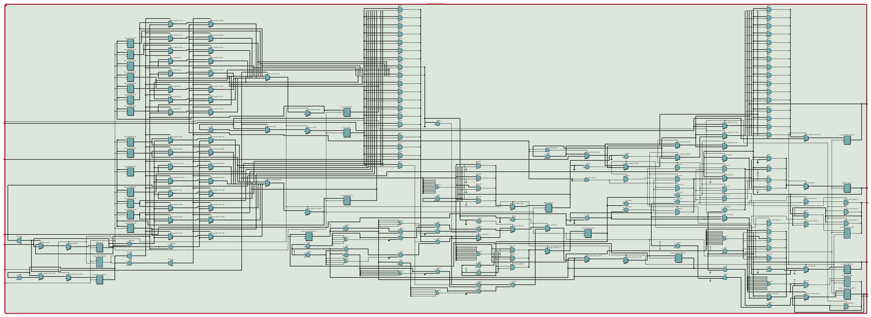
This project is a FPGA remake of the Super Nintendo audio system, written in Verilog. It runs on real hardware. We (the authors) are building this on a Cyclone V GX FPGA devboard.
The SNES audio system is composed of two primary systems, the SPC700 CPU (very similar to the 6502), and a custom 8-voice DSP. The two processors work together and share a single block of 64KiB RAM. On a real console, the audio RAM is initially seeded with data from the primary CPU of the SNES, but in our system, we will populate the RAM and CPU/DSP state with meaningful data in order to drive/start execution. The SPC700 is typically running a "driver" program which keeps track of time and sets various DSP registers to the appropriate values as time goes on. The DSP itself is totally configured via registers and does not run any code. The DSP is responsible
This project follows reasonably closely the timing constraints and behavior of the real SNES audio system, but this is not an attempt to have 100% accuracy as this is much more complex to achieve and 100% accuracy is not our goal.
The DSP itself constantly needs to load sample data and service external reads/writes with the CPU. There are 8 voices in the DSP that each need to generate a sample for mixing at 32Khz. To that end, each span of (1 second / 32Khz) time is sliced into 64 steps and accesses to RAM for each voice follows a fixed schedule (see dsp_schedule.txt). By the end of the schedule, a final mixed audio sample (a 16-bit signed L/R pair) is ready to be pushed over I2S to the audio DAC.
The DSP itself has 8 instances of DSP Voice Decoders which do the work of decoding sample data in parallel. These decoders each follow a state machine to minimally fill a small ring buffer while decompressing the "BAR"-encoded sample data that the SNES uses. Each decoder advances forward in time at a configured speed (which controls sample pitch). Because achieving higher pitches requires actually reading and processing input compressed data faster and faster, we have a cap on the maximum amount you can speed up any given sample; In order to avoid the need for faster processing speeds, we have the same limitation as the real hardware of a maximum pitch of +2 octaves higher than the nominal sample frequency. DSP sample data is currently linearly interpolated between the two most recent samples while the real hardware does a gaussian filtering.
This project supports one DAC which is present on the FPGA devboard used by the authors (Analog Devices' SSM2603). The configuration over I2C and I2S sample data is all written as part of this project and not imported HW IP. Because this project only needs to support stereo 32khz audio data, configuration/bringup is fairly simple. I will mention we initially thought this was going to be simpler until we read the datasheets more closely and realized there is a bit of setup for the device.
There are several components:
- Verilog code - The main bits of the project...
- DSP Voice Decoder - Does the work of reading and decoding BAR compressed data from RAM and producing a mono audio sample for each of the 8 voices.
- DSP - Mixes the 8 voice decoders. Configurable via a bank of >200 registers which will eventually be controlled by the SPC700.
- SPC700 - The "CPU" of the audio system. This architecture is extremely close to a 6502. It is responsible for running "driver" code which actually represents the music being played and transforms these into DSP register changes over time. It "plays" the DSP according to the machine code in RAM.
- RAM - Shared between the SPC700 and the DSP. This is a fairly simple block of dual-port 64KiB RAM which contains everything: the machine code the SPC700 is running, the sample data the DSP is reading from, etc. It also contains FIR delay ring buffer data which the DSP can make use of. It's up to the user code to properly manage and account for usage of RAM.
- Audio DAC - Our project has support for the SSM2603 which receives a stream of L/R 16-bit samples at a rate of 32Khz from the DSP so that you can actually listen to everything.
- Serial Driver - The driver.py speaks with the FPGA over serial. There is a very simple "command" protocol (see uart_commands.md) which enables you to place data into RAM, set DSP register states, set DAC volume, etc. While we continue to work on setting up the SPC700 CPU,
make -j && ./build/DSPVoiceDecoder ./test_data/13_piano.brr && play ./build/dsp_voice_test_wave_out.wav
make && time ./build/TestDSP ./test_data/13_piano.brr && play ./build/dsp_test_wave_out.wav
# Make sure we have: 460800 baud, 1 stop bit, no parity bit
sudo stty -F /dev/ttyUSB0 cs8 -parenb -cstopb -clocal -ixon -inpck 460800

# You can reset Audio Codec I2C regs
python3 driver.py --reset-audio

# Reset APU (e.g. replay a sound at RAM 0x0000 for now)
python3 driver.py --reset-apu

# Send data to RAM
python driver.py --load-sample [sample_path]
out.mp4
- Noise Generator
- Master Volume
- ADSR Envelope Generator
- Gaussian Sample Filtering
- Pitch Modulation
- Echo Buffer