Implementing a contrast mask refinement#8597
Implementing a contrast mask refinement#8597jenshannoschwalm wants to merge 5 commits intodarktable-org:masterfrom
Conversation
What is this about?
For some use cases we want to discriminate image areas with lots of detail from those without.
So it is basically not about border or shape detection but something that should be understood
as looking for pixelwise local contrast.

This idea is used already in darktables dual demosaicing code (to discriminate areas with high
frequency content from thos without) and some algorithms in rawtherapee (microcontrast, sharpening,
capture sharpening ...) so we know it works really good.

The user interface is pretty simple, for every mask offering a refinement box there is an additional
slider defining a threshold for the contrast mask. (details later)
Positive slider values select for contrasty, negative values for flat regions.

What are the use cases of this mask refinement?
Right now we can use modules like sharpening, locat contrast, denoising to work only on image areas
most suitable. Or we can brighten up some areas with lots of details.
In the longer term this will be the basis of yet to be implemented modules we can take from rt, i will
certainly port capture sharpening to dt.

As @aurelienpierre pointed out in the discussion about darktable-org#8501, the underlying algorithm is a bit
more difficult to implement with darktables roi concept as the calculated contrast value is
not reliable after scaling, rotation or even simple things as exposure corrections.
I tried his suggestions but the original algorithm seems to be better suited for the purpose
described. So for calculating the first pixel contrast i kept the "weird thing"

So i wanted to find a way keeping "contrast masks" working exactly as in the original implmentations.
To get you into faster understanding the code, some details.

Whenever we set this slider to a value != 0 the demosaic or rawprepare module are forced to write
a *preliminary* contrast mask, this mask has always the size of the roi_out of that module.
It is *not* scaled but only clipped so it still contains pure pixel data.
This preliminary mask is valid and used for every mask using a "local contrast" refining step.

Whenever a mask in any module wants a "local contrast" refinement it
a) takes the preliminary mask and calculates a 'mask overlay' using the threshold to calculate a sigmoid
   value 0->1 for every pixel
b) the just calculated mask overlay is now transformed through the pipeline using the modules 'distort'
   functions, the resulting "warped" contrast mask is now combined with the defined drawn or parametric
   mask.

- opencl code has been impemented
- some shared code with rcd and dual demosaicing has been de-duplicated
|
What exactly didn't work in my proposal ? I'm always suspicious when correct maths work worse than hacky algos without clear theoritical grounds. |
I carefully read your comments and suggestions especially about the gradients ... absolutely correct. Of course they improved the mask output. But the generated mask still was very dependent on the scale in darkroom view (also we have scaling artefacts here depending on the used algo). It detected edges much much better (and your paper-in-pipe explained this is detail) but: the question here is: how do we detect a small region (lets say 5x5 pixels) in the original image having local pixel differences / local contrast? As you pointed out the "weird thing" added gradients in a "hacky" way. Isn't this exactly why the used algo can detect such areas as is equally weighs those distances? BTW i also looked at the focus peaking code as that seemed to be cosely related ... maybe i misunderstand the code but also here i see the peak-overlay depending on the image size. So i think, the preliminary mask is good as it's a stable base for further processing so any modules switchend on/off before doing the contrast mask won't affect it. |
The focus-peaking is a vanilla second order gradient (laplacian), it's not exactly the same (gradients represent transitions, laplacians represents curvature).
OOOOOkay, I missed that. So the weird thing you compute is a patch-wise variance measure : It would have saved us a lot of time if some background equations were provided with the code, or at least the variables in the code were properly named by what they actually represent. |
I will add such info. At least for me this discussion has not been wasted time :-) |
As @aurelienpierre suggested we need some docs about ideas and impementation details
of the contrast mask algorithm.
|
CI failing is not related to this pr btw. |
|
Just a quicky, as I am very busy these days/weeks/months... :-) It is easy to handle. A combined drawn+parametric mask, where the drawn mask getting inverted, results in something unexpected (TBH I saw that before, so it is 99.99% nothing about this PR).
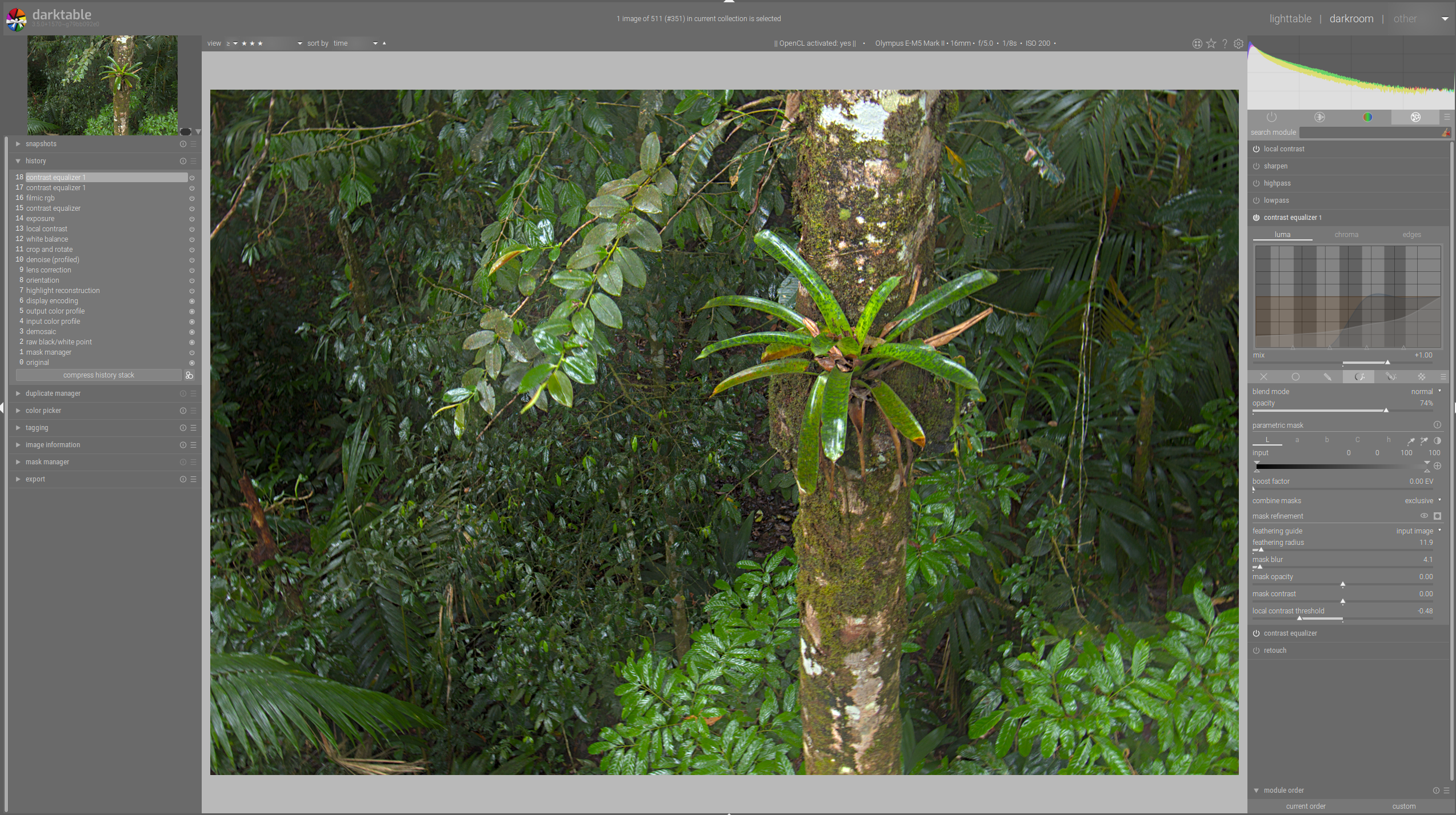
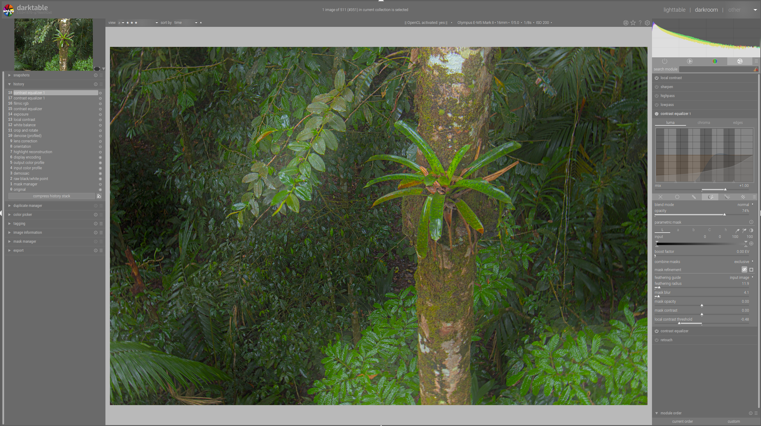
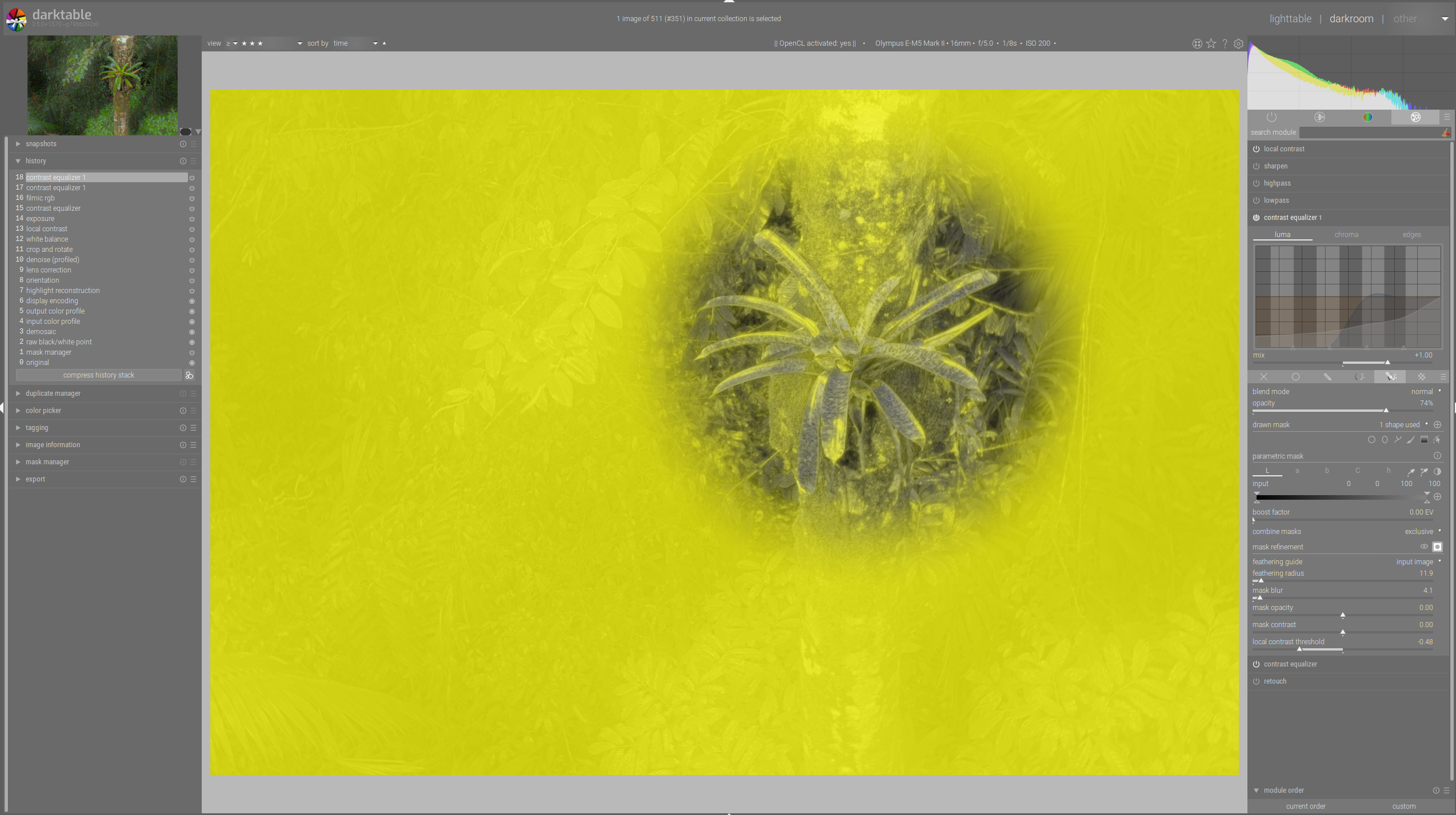
But first things first: lct-mask: Faked smaller DOF: w/o lct-mask: So there is an effect, which I am very grateful about (did not spend real time to attenuate) And finally the inverted drawn mask together with the parametric one, wehere I expect the effect outside the circle and not inside, as it is shown here: |
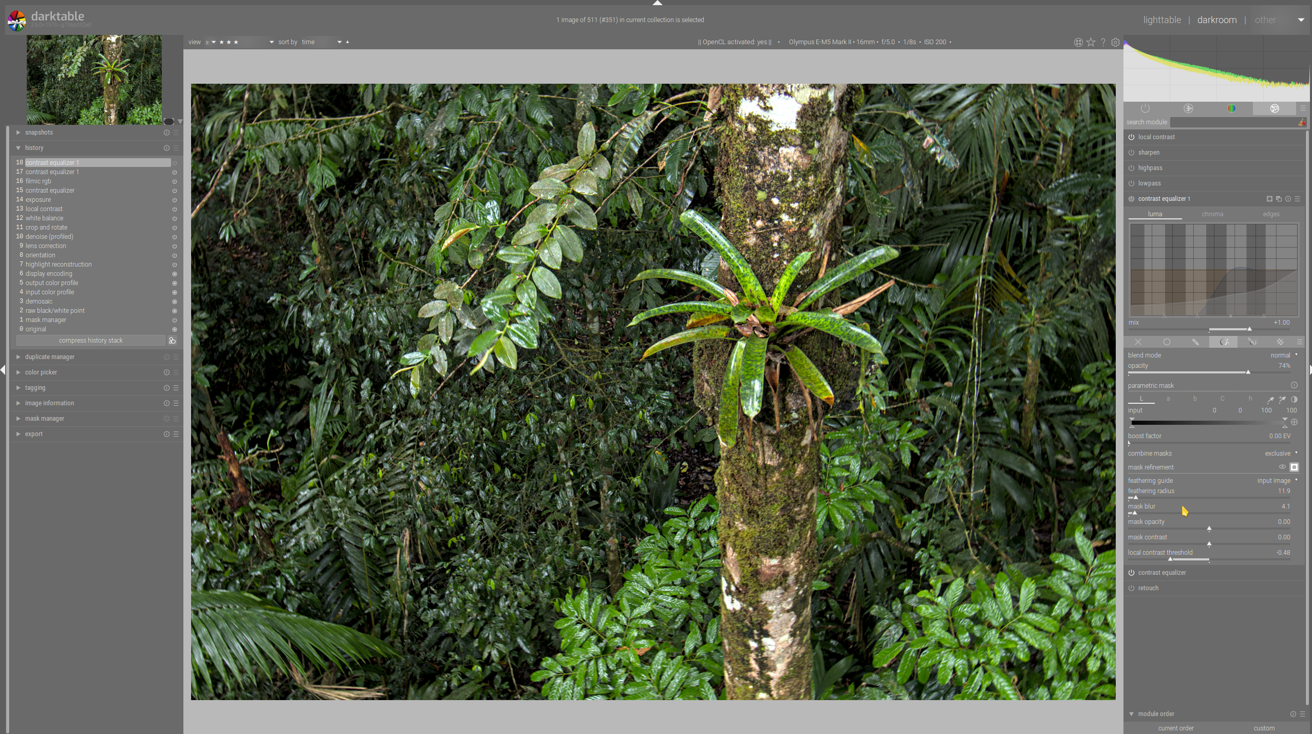
When using an inverted mask the refining via the contrast mask used a double-inverting which was not
correct. Observed by @AxelG-DE
1. Lots of renaming as aurelienpierre hinted at to make the code more readable

2. The intermediate mask kept in the pipeline struct had already been corrected for
the luminance variances. Better for performance but restricting the usability by possibly
other intentions. It now holds luminances in labf space.
|
Just to leave a note, everything works just right now and i will re-open another pr after the rcd maintenance update has been merged for an easier review and testing in case the feature freeze for 3.6 comes too early. |
After closing #8501 this is a better approach ... pinging @aurelienpierre and @AxelG-DE
What is this about?
For some use cases we want to discriminate image areas with lots of detail from those without. So it is not the desire about border or shape detection but something that should be understood as looking for pixelwise local contrast.
This idea is used already in darktable's dual demosaicing code (to discriminate areas with high frequency content from those without) and some algorithms in rawtherapee (microcontrast, sharpening, capture sharpening ...) so we know it works really good.
The user interface is pretty simple, for every mask offering a refinement box there is an additional slider defining a threshold for the contrast mask. (details later) Positive slider values select for contrasty, negative values for flat regions.
What are the use cases of this contrast mask refinement?
We would like to use modules like sharpening, local contrast, denoising to work only on image areas most suitable. Or we can brighten up some areas with lots of details.
Also the contrast mask will be the basis of yet to be implemented modules, i will certainly port rt's capture sharpening to dt.
About the first pr discussion
As @aurelienpierre pointed out in the discussion about #8501, the underlying algorithm is a bit more difficult to implement with darktable's roi concept as the calculated contrast value is not reliable after scaling, rotation or even simple things as exposure corrections.
I tried his suggestions but the original algorithm seems to be better suited for the purpose described above.
So for calculating the first pixel contrast i kept the "weird thing" and had to find a way keeping "contrast masks" working exactly as in the original implementation. The "weird thing" code has been taken from rt, the originating code is from the microcontrast code there.
To get you into faster understanding the code, some implementation details.
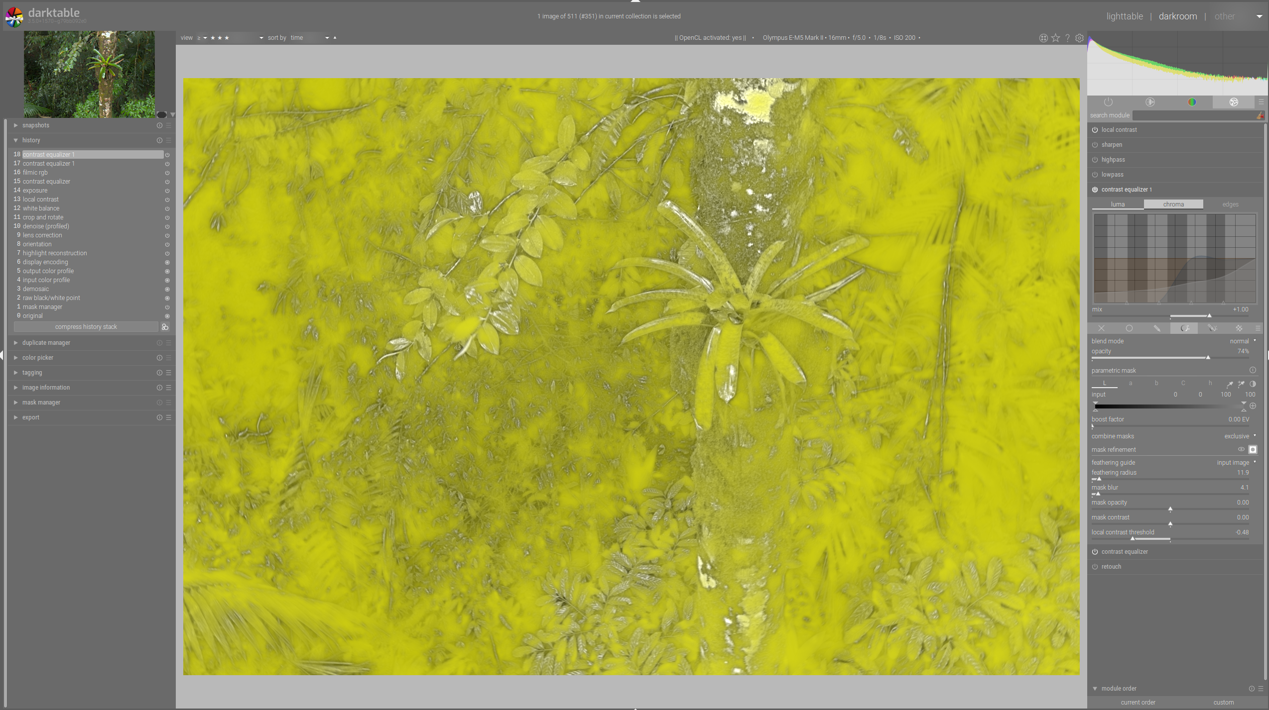
Whenever we set this slider to a value != 0 the demosaic or rawprepare modules are forced to write a preliminary contrast mask, it always has the size of the roi_out of that module, it is not scaled but only clipped so it still contains pure pixel data.
This preliminary mask is calculated only once whenever the writing module is processed and is later used for every mask using a "local contrast" refining step.
Whenever a mask in any module wants a "local contrast" refinement it
a) takes the preliminary mask and calculates a 'mask overlay' using the threshold to calculate a sigmoid value 0->1 for every pixel
b) the just calculated mask overlay is now transformed through the pipeline using the modules 'distort' functions, the resulting "warped" contrast mask is now combined with the defined drawn or parametric mask.