Z80 Bare-Metal Dino Runner on a Real OLED Display
YESOD is a hardware retro-game project: a tiny Dinosaur Runner (inspired by the Chrome offline dino game) running on a real Zilog Z80 CPU, with an SSD1306 128×64 OLED display driven over a bit-banged I2C bus, and an Arduino Nano acting as a ROM emulator.
No HAL. No libraries. No OS. Just pure Z80 Assembly, raw I/O ports, and precise bit-banging.
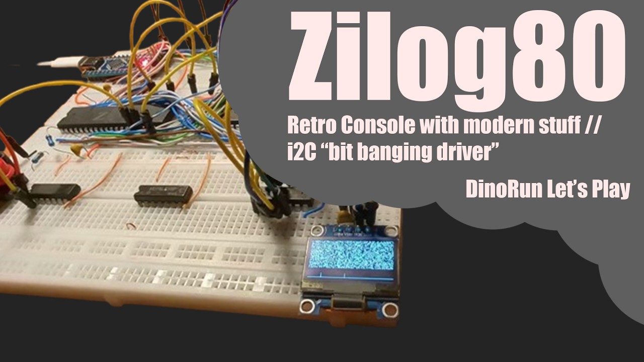
| Component | Role |
|---|---|
| Zilog Z80 | Main CPU — runs the game loop |
| Arduino Nano (ATmega328P) | ROM emulator — serves Z80 machine code over the data bus |
| SSD1306 128×64 OLED | Display — connected via I2C (bit-banged through Z80 I/O port 0xFF) |
| Button | Jump input — triggers Z80 INT (mode 1 interrupt at 0x0038) |
The schematic below shows the full bus wiring:

0x0000 ┌─────────────────────────────────────────┐
       │                                         │
       │   ROM  (32 KB)                          │
       │   Served by Arduino Nano over data bus  │
       │                                         │
       │   0x0000  _start, I2C routines          │
       │   0x0038  INT handler (jump button)     │
       │   0x004D  _i2c_write                    │
       │   0x006C  _ssd1306_Init                 │
       │   0x008E  _init_seq_data                │
       │   0x009C  _ssd1306_UpdateScreen         │
       │   0x00ED  _init_and_main / game loop    │
       │                                         │
0x7FFF └─────────────────────────────────────────┘
0x8000 ┌─────────────────────────────────────────┐
       │                                         │
       │   RAM  (32 KB)                          │
       │                                         │
       │   0x8000–0x82FF   unused                │
       │                                         │
       │   0x8300–0x83FF   Frame buffer (256 B)  │
       │   ├─ 0x8300–0x837F  Page 6 — jump row  │
       │   │     0x8314 = dino column (air)      │
       │   └─ 0x8380–0x83FF  Page 7 — floor row │
       │         0x8394 = dino column (ground)   │
       │         0x8380+X = cactus position      │
       │                                         │
       │   0x8400   Cactus X position            │
       │   0x8401   Jump flag (1 = jumping)      │
       │   0x8402   Jump timer countdown         │
       │   0x8403   Game-over flag               │
       │                                         │
       │   0x8404–0xFFFF   unused                │
       │                                         │
       │   0xA000           Stack pointer (SP)   │
       │                                         │
0xFFFF └─────────────────────────────────────────┘
The entire game logic lives in crt0.s — a single Z80 assembly file compiled with SDCC/SDASZ80.
_startat0x0000: disables interrupts, sets up stack at0xA000, enables IM 1 mode, configures I2C lines, and jumps to_init_and_main._ssd1306_Init: sends the SSD1306 initialisation sequence over bit-banged I2C.- Variables are zeroed, interrupts enabled — game loop starts.
Each frame:
- Clear the frame buffer — 256 bytes at
0x8300–0x83FF(pages 6–7) filled with zeros. - Draw the floor — a row of
0x80bytes at0x8380. - Check game-over flag — if set, draw two
>symbols ("eyes") and skip to frame send. - Dino logic — dino is at a fixed column (
0x14or0x94in the floor row). If the jump flag is set, draw it in the air row (0x8314) and decrement the jump timer; when timer hits zero, clear the jump flag. - Cactus logic — draw a
0xFFbyte at the cactus's current X position in the floor row. Move the cactus left by 4 pixels per frame; wrap around at0. - Collision detection — if the cactus X is between 9 and 23 and the dino is NOT jumping → set game-over flag.
- Send frame via
_ssd1306_UpdateScreen(I2C transfer of the whole frame buffer to the OLED).
Triggered by the jump button (INT line). Sets the jump flag and loads the jump timer (10 ticks) if the dino is not already airborne.
Port 0xFF value |
Meaning |
|---|---|
0x00 |
SDA=0, SCL=0 |
0x01 |
SDA=1, SCL=0 (START condition) |
0x02 |
SDA=0, SCL=0 → 0x03 SCL=1 (clock pulse) |
0x03 |
SDA=1, SCL=1 (idle / STOP) |
_i2c_write shifts out 8 bits MSB-first with clock pulses; ACK bit is sent but not checked (display assumed always ready).
yesod/
├── crt0.s            # ★ Main game source — full Z80 assembly
├── run.py            # Build script: assembles → compiles → generates z80_rom.h
├── z80_rom.h         # Generated ROM byte array (included in the Arduino sketch)
├── pasmo.exe         # Pasmo Z80 assembler (Windows binary, alternative toolchain)
├── schemat.jpg       # Hardware wiring schematic
└── sketch/
    └── sketch.ino    # Arduino Nano ROM emulator firmware
- SDCC — Small Device C Compiler (provides
sdcc+sdasz80) - Python 3 — for the build script
- Arduino IDE — to flash the Nano
python run.pyThe script does the following:
- Cleans old intermediate build files (
.rel,.ihx,.lk,.lst,.map,.noi,.sym). - Assembles
crt0.swithsdasz80. - Links
crt0.relwithsdccplacing code at0x0000and data at0x8000. - Parses the resulting
main.ihx(Intel HEX) and extracts ROM bytes (addresses below0x8000). - Writes the ROM as a C byte array to
z80_rom.h.
- Open
sketch/sketch.inoin the Arduino IDE. - Make sure
z80_rom.his up to date (runpython run.pyfirst). - Upload to the Arduino Nano — it will serve ROM bytes to the Z80 data bus on every
~RDpulse.
sketch/sketch.ino configures the ATmega328P pins as follows:
| Arduino pins | Role |
|---|---|
PORTD (D0–D7) |
Z80 Data Bus (bidirectional, output when serving ROM) |
PORTC (A0–A5) |
Address bus bits A0–A5 |
PORTB (D8–D11) |
Address bus bits A6–A9 |
PORTB bit 1 (D9) |
~RD signal from Z80 |
PORTB bit 0 (D8) |
~OE / data-enable output |
On each falling edge of ~RD, the Nano reads the 10-bit address (A0–A9), looks it up in z80_rom[], and drives the data bus with the corresponding byte. After ~RD goes high, the data bus is tri-stated.
This project is open-source. Feel free to study, modify, and build on it.