Constraints
Constraints are used to describe specific aspects in the MOSIM environment and are defined in the Constraints.thrift file. As thrift does not define inheritance, the following trick is utilized. MConstraint is the general class for each constraint. All specific constraints are optional parameters of MConstraint. Hence, if you want to provide a specific constraint, e.g. the MGeometryConstraint, you first need to define a variable c_specific of type MGeometryConstraint and afterwards a second variable c_container of type MConstraint. Afterwards, assign c_specific to the c_container.GeometryConstraint optional field. Make sure, that each only a single specific constraint is set for a single general constraint.
| MConstraint |
|---|
| + ID: string + GeometryConstraint: MGeometryConstraint + VelocityConstraint : MVelocityConstraint + AccelerationConstraint : MAccelerationConstraint + PathConstraint : MPathConstraint + JointPathConstraint : MJointPathConstraint + PostureConstraint : MPostureConstraint + JointConstraint : MJointConstraint + Properties: map<string, string> |
Detailed description of available parameters:
| Parameter Name | Required | Description |
|---|---|---|
| ID | x | Unique id of the constraint. |
| GeometryConstraint | An assigned geometry constraint (if defined). | |
| VelocityConstraint | An assigned velocity constraint (if defined). | |
| AccelerationConstraint | An assigned acceleration constraint (if defined). | |
| PathConstraint | An assigned path constraint (if defined). | |
| JointPathConstraint | An assigned joint path constraint (if defined). | |
| PostureConstraint | An assigned posture constraint (if defined). | |
| JointConstraint | An assigned joint constraint (if defined). | |
| Properties | Optional properties, which can be specified. |
The following datatypes are used by several constraints to define intervals, translations and rotations.
MInterval defines min and max boundaries. Boundaries (min, max) can be infinity and -infinity.
| MInterval |
|---|
| +Min: double +Max: double |
Detailed description of available parameters:
| Parameter Name | Required | Description |
|---|---|---|
| Min | yes | Value for min boundary |
| Max | yes | Value for max boundary |
Examples for constraint values:
new interval_1 = MInterval(0.0, 0.0)
new interval_2 = MInterval(0.0, Infinity)
new interval_3 = MInterval(-Infinity, -4.0)MInterval3 defines min and max boundaries in a three dimensional coordinate system.
| MInterval3 |
|---|
| +X: MInterval +Y: MInterval +Z: MInterval |
Detailed description of available parameters:
| Parameter Name | Required | Description |
|---|---|---|
| X | yes | Interval in x-axis (right) direction. |
| Y | yes | Interval in y-axis (up) direction. |
| Z | yes | Interval in z-axis (forward) direction. |
Examples for constraint values:
new interval3_1 = MInterval3(interval_1, interval_2, interval_3)
new interval3_2 = MInterval3(interval_1, interval_1, interval_1)Positive and negative extent of the box or ellipsoid along the coordinate axes. Translation is defined along the coordinate system axes using right hand rule. Unit = [mm]. May take values of 0 to +-inf. If not given intervals [0,0] are assumed.
| MTranslationConstraint |
|---|
| +Type: MTranslationConstraintType +Limits: MInterval3 |
Detailed description of available parameters:
| Parameter Name | Required | Description |
|---|---|---|
| Type | yes | Geometric type of translation. (Box or Ellipsoid) |
| Limits | yes | Translation limits along the coordinate system. |
Examples for constraint values:
new trl_constr_1 = new MTranslationConstraint(MTranslationConstraintType.BOX, interval3_1)Enumerate type for choosing a translation constraint type.
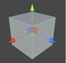
BOX: Box that is orientated along the xyz-axes.
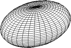
ELLIPSOID: Ellipsoid that is orientated along the xyz-axes.
| <<enum>> MTranslationConstraintType |
|---|
| +BOX +ELLIPSOID |
Rotation is defined along the coordinate system axes using right hand rule. Unit = [rad]. If not given intervals [-inf,inf] are assumed.
| MRotationConstraint |
|---|
| +Limits: MInterval3 |
Detailed description of available parameters:
| Parameter Name | Required | Description |
|---|---|---|
| Limits | yes | Rotational limits along the coordinate system. |
Examples for constraint values:
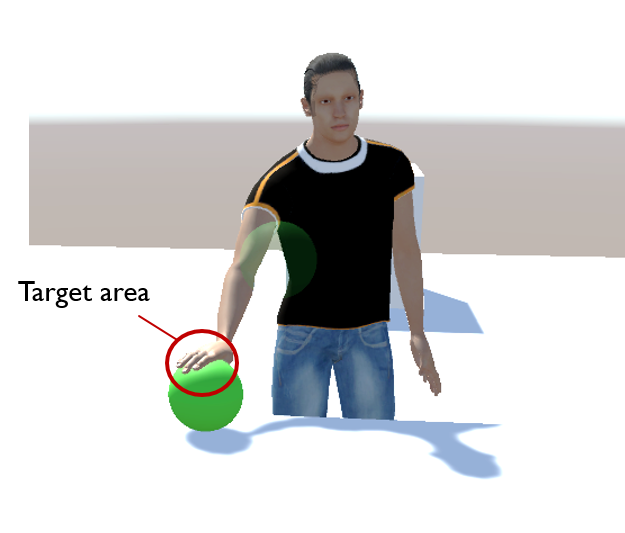
new rot_constr_1 = new MRotationConstraint(interval3_1)Defines a target area in relation to an object, which will be constrained.
| MGeometryConstraint |
|---|
| +ParentObjectID: string +ParentToConstraint: MTransform +TranslationConstraint: MTranslationConstraint +RotationConstraint: MRotationConstraint +WeightingFactor: double |
| Parameter Name | Required | Description |
|---|---|---|
| ParentObjectID | yes | ID of an object in the scene graph. The object's base coordinate system serves as base for the constraint definition. |
| ParentToConstraint | no | Transformation from parent base coordinate system to constraint base coordinate system (cs_C). This coordinate system (cs_C) represents the centroid of the TranslationConstraint or RotationConstraint. If not given -> identity matrix is assumed. |
| TranslationConstraint | no | TranslationConstraint with cs_C as base. |
| RotationConstraint | no | RotationConstraint with cs_C as base. |
| WeightingFactor | no | Linear factor with values of 0 to 1. 1 has to be at exact point, 0 functions as a hint. |
Examples for constraint values:
new geo_constr_1 = MGeometryConstraint("<ObjID>")
new geo_constr_2 = MGeometryConstraint("<ObjID>", ParentToConstraint=trafo_1)
new geo_constr_3 = MGeometryConstraint("<ObjID>", ParentToConstraint=trafo_1, TranslationConstraint=trl_constr_1)
new geo_constr_4 = MGeometryConstraint("<ObjID>", ParentToConstraint=trafo_1, RotationConstraint=interval3_2, WeightingFactor=0.9)Constraining the velocity of an object.
| MVelocityConstraint |
|---|
| +ParentObjectID: string +ParentToConstraint: MTransform +TranslationalVelocity: MVector3 +RotationalVelocity: MVector3 +WeightingFactor: double |
Detailed description of available parameters:
| Parameter Name | Required | Description |
|---|---|---|
| ParentObjectID | yes | ID of an object in the scene graph. The object's base coordinate system serves as base for the constraint definition. |
| ParentToConstraint | no | Transformation from parent base coordinate system to constraint base coordinate system (cs_C). This coordinate system (cs_C) represents the centroid of the TranslationConstraint or RotationConstraint. If not given -> identity matrix is assumed. |
| TranslationVelocity | no | Vector for translation constraint with cs_C as base. Unit = [m/s] |
| RotationVelocity | no | Vector for rotation constraint with cs_C as base. Unit = [rad/s] |
| WeightingFactor | no | Linear factor with values of 0 to 1. 1 has to be at exact point, 0 functions as a hint. |
Examples for constraint values:
new v_constr_1 = MVelocityConstraint("<ObjID>")
new v_constr_2 = MVelocityConstraint("<ObjID>", ParentToConstraint=trafo_1)
new v_constr_2 = MVelocityConstraint("<ObjID>", TranslationalVelocity=new MVector3(1.0, 3.0, 0.0))
new v_constr_2 = MVelocityConstraint("<ObjID>", TranslationalVelocity=new MVector3(1.0, 3.0, 0.0), RotationalVelocity = new MVector3(0.0, 0.0, 0.0))Constraining the acceleration of an object.
| MAccelerationConstraint |
|---|
| +ParentObjectID: string +ParentToConstraint: MTransform +TranslationalAcceleration: MVector3 +RotationalAcceleration: MVector3 +WeightingFactor: double |
Detailed description of available parameters:
| Parameter Name | Required | Description |
|---|---|---|
| ParentObjectID | yes | ID of an object in the scene graph. The object's base coordinate system serves as base for the constraint definition. |
| ParentToConstraint | no | Transformation from parent base coordinate system to constraint base coordinate system (cs_C). This coordinate system (cs_C) represents the centroid of the TranslationConstraint or RotationConstraint. If not given -> identity matrix is assumed. |
| TranslationalAcceleration | no | Vector for translation constraint with cs_C as base. Unit = [m/s^2] |
| RotationalAcceleration | no | Vector for rotation constraint with cs_C as base. Unit = [rad/s^2] |
| WeightingFactor | no | Linear factor with values of 0 to 1. 1 has to be at exact point, 0 functions as a hint. |
Examples for constraint values:
new acc_constraint_1 = MAccelerationConstraint("<ObjID>", TranslationalAcceleration=new MVector3(0.1, 1.0, 0.0)))Describes a path to follow, consisting of polygon points.
| MPathConstraint |
|---|
| +PolygonPoints: list +WeightingFactor: double |
Detailed description of available parameters:
| Parameter Name | Required | Description |
|---|---|---|
| PolygonPoints | yes | A predefined path, consisting out of MGeometryConstraints contained in a list format. |
| WeightingFactor | no | Linear factor with values of 0 to 1. 1 has to be at exact point, 0 functions as a hint. |
Examples for constraint values:
new path_constraint_1 = MPathConstraint(new List(geo_constr_1, geo_constr_2, geo_constr_3))Defines a path for specific joint of an avatar.
| MJointPathConstraint |
|---|
| +JointType: MJointType +PathConstraint: MPathConstraint |
Detailed description of available parameters:
| Parameter Name | Required | Description |
|---|---|---|
| JointType | yes | Type of the designated joint of the avatar |
| PathConstraint | yes | Defined path for the corresponding joint. |
Examples for constraint values:
new joint_path_constraint_1 = MJointPathConstraint(MJointType.RightWrist, path_constraint_1)Defines a joint of an avatar, which then will be affected by different constraint types.
| MJointConstraint |
|---|
| +JointType: MJointType +GeometryConstraint: MGeometryConstraint +VelocityConstraint: MVelocityConstraint +AccelerationConstraint: MAccelerationConstraint |
Detailed description of available parameters:
| Parameter Name | Required | Description |
|---|---|---|
| JointType | yes | Type of the designated joint of the avatar |
| GeometryConstraint | no | |
| VelocityConstraint | no | |
| AccelerationConstraint | no |
Examples for constraint values:
new joint_constraint_1 = MJointConstraint(MJointType.RightWrist, GeometryConstraint=geo_constr_2)
new joint_constraint_2 = MJointConstraint(MJointType.RightWrist, GeometryConstraint=geo_constr_2, VelocityConstraint=v_constr_1)Describes a predefined avatar posture. The posture can be defined in two ways. First, a (partial) posture as MAvatarPostureValues can be provided. Second, joint constraints can be provided for individual joints. The second option is ideal if global joint positions are supposed to be defined. It is possible, to provide empty AvatarPostureValues and constrain the posture purely with joint constraints.
| MPostureConstraint |
|---|
| +posture: MAvatarPostureValues +JointConstraints: list |
Detailed description of available parameters:
| Parameter Name | Required | Description |
|---|---|---|
| Posture | yes | Specific posture of an avatar. |
| JointConstraints | no | Required avatar joints for creating the posture. |
new interval_1 = MInterval(0.0, 0.0)
new interval_2 = MInterval(0.0, Infinity)
new interval_3 = MInterval(-Infinity, -4.0)

new interval3_1 = MInterval3(interval_1, interval_2, interval_3)
new interval3_2 = MInterval3(interval_1, interval_1, interval_1)

new trl_constr_1 = new MTranslationConstraint(MTranslationConstraintType.BOX, interval3_1)

new trafo_1 = MTransform("<ObjID>")

new geo_constr_1 = MGeometryConstraint("<ObjID>")
new geo_constr_2 = MGeometryConstraint("<ObjID>", ParentToConstraint=trafo_1)
new geo_constr_3 = MGeometryConstraint("<ObjID>", ParentToConstraint=trafo_1, TranslationConstraint=trl_constr_1)
new geo_constr_4 = MGeometryConstraint("<ObjID>", ParentToConstraint=trafo_1, RotationConstraint=interval3_2, WeightingFactor=0.9)

new v_constr_1 = MVelocityConstraint("<ObjID>")
new v_constr_2 = MVelocityConstraint("<ObjID>", ParentToConstraint=trafo_1)
new v_constr_2 = MVelocityConstraint("<ObjID>", TranslationalVelocity=new MVector3(1.0, 3.0, 0.0))
new v_constr_2 = MVelocityConstraint("<ObjID>", TranslationalVelocity=new MVector3(1.0, 3.0, 0.0), RotationalVelocity = new MVector3(0.0, 0.0, 0.0))

new path_constraint_1 = MPathConstraint(new List(geo_constr_1, geo_constr_2, geo_constr_3))

new joint_constraint_1 = MJointConstraint(MJointType.RightWrist, GeometryConstraint=geo_constr_2)
new joint_constraint_2 = MJointConstraint(MJointType.RightWrist, GeometryConstraint=geo_constr_2, VelocityConstraint=v_constr_1)

new joint_path_constraint_1 = MJointPathConstraint(MJointType.RightWrist, path_constraint_1)

new acc_constraint_1 = MAccelerationConstraint("<ObjID>", TranslationalAcceleration=new MVector3(0.1, 1.0, 0.0)))

new joint_list_1 = [MJointType.RightWrist, MJointType.LeftWrist]In the following examples, the x-axis is colored in red and points in the direction of the surface normal. The y-axis is colored in green and points in the direction of the hand. The z-axis is colored in blue.
The following is a proposal on how reach positions can be described with the MGeometry Constraint. This is also a proposal for a project wide standard for describing the coordinate systems of an object for interaction points.
As a standard procedure it is proposed to define the x-axis to point outwards the surface, and the z-axis downwards. Exeption to this is the chair, as mentioned below.
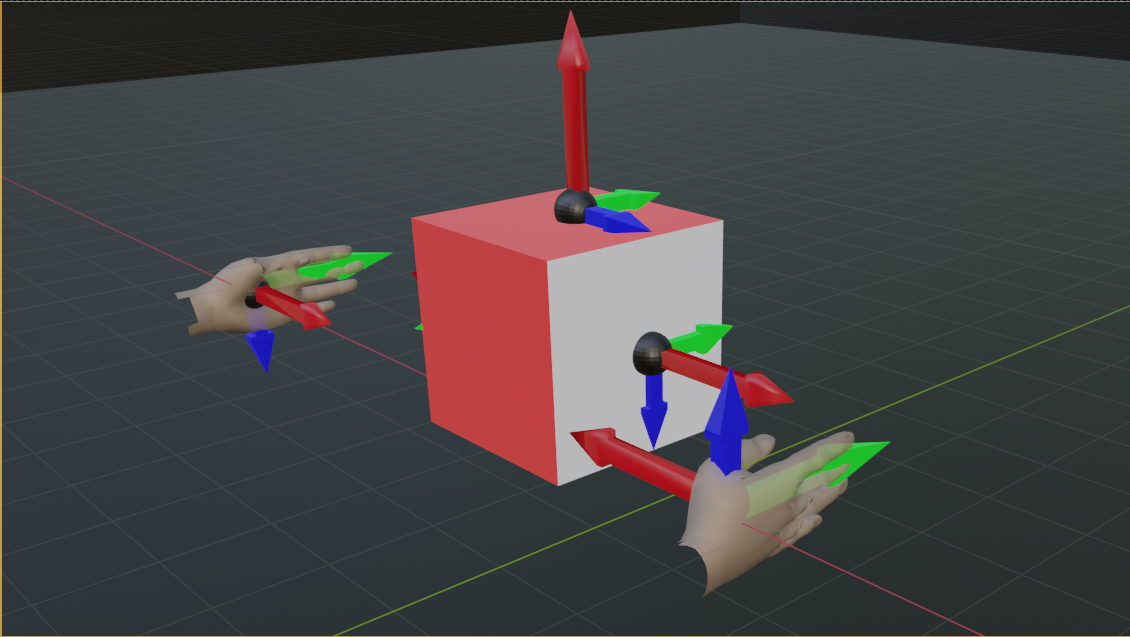
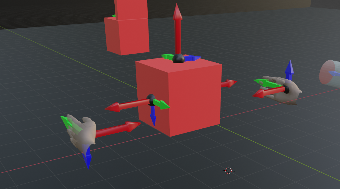
As depicted in the image, this demonstrates the placement of an MGeometryConstraint on a flat surface (e.g. side of a box).
- The ParentToConstraint has the box transform as its parent id and provides a local transformation within the coordinate system of the box to place the constraint on the center of the boxes side surface with the x-axis pointing to the surface normal as depicted in the image.
- The translation constraint has boundaries (x,y,z) of [0,0], [-side_y/2, +side_y/2], [-side_z/2, + side_z/2]
- The rotation constraint has boundaries (x,y,z) of [-inf, +inf], [0, 0], [0, 0].
This means, that any part of the surface can be reached from any direction.
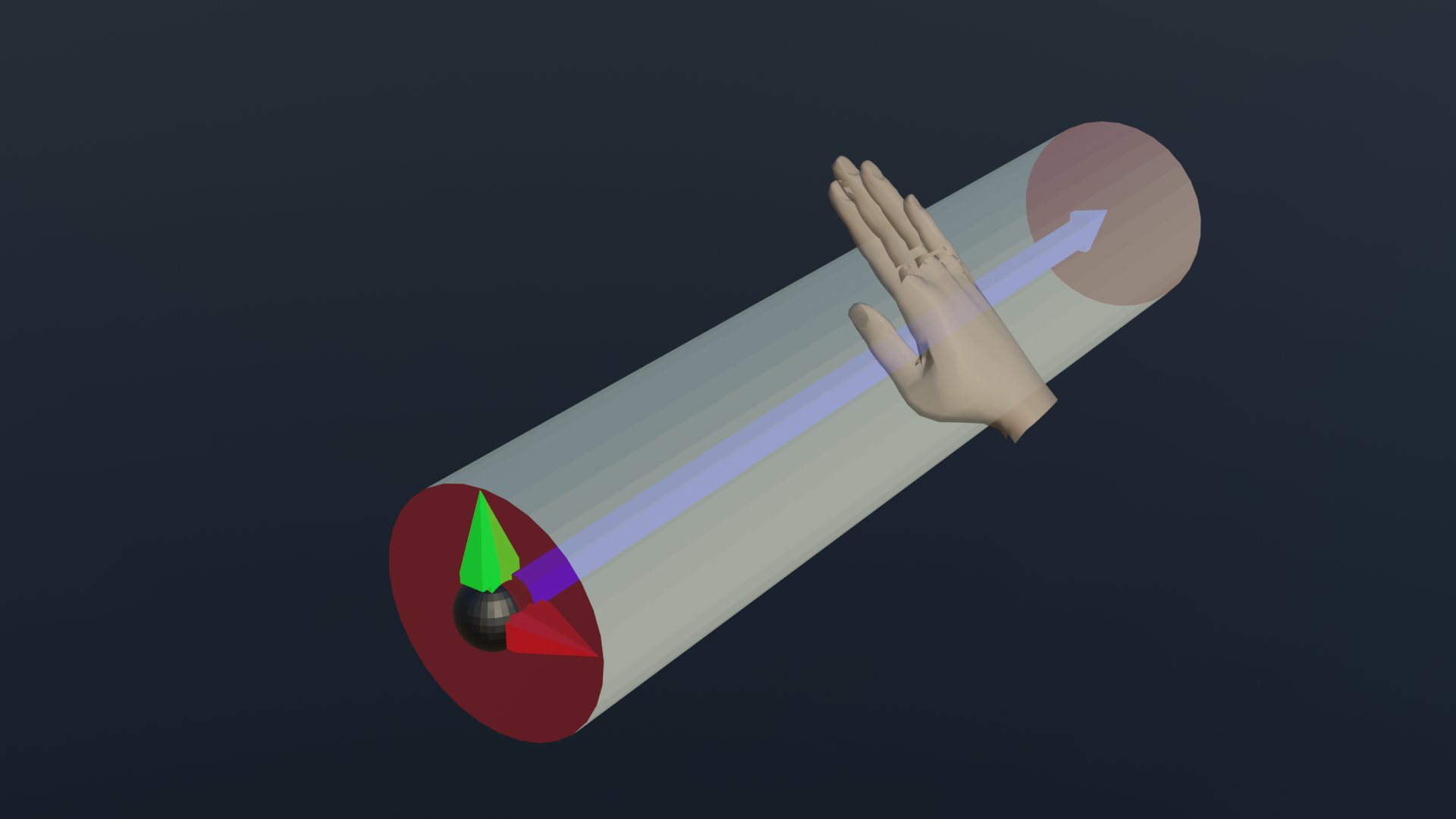
As depicted in the image, this demonstrates the placement of an MGeometryConstraint on a cylindrical surface (e.g. metal bar). * The ParentToConstraint places the constraint at the end of the handle with the z axis pointing along the axis of the cylinder as depicted in the image.
- The translation constraint has boundaries (x,y,z) of [+radius_x, + radius_x], [+radius_y, +radius_y], [0, lenght]
- The rotation constraint has boundaries (x,y,z) of [0, 0], [0, 0], [-inf, +inf]
Thus, the cylinder can be reached on any point on the surface at any rotation around the axis of the cylinder.
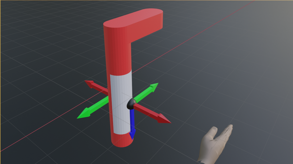
As depicted in the image, this demonstrates the specific placement of an MGeometryConstraint on a tool, which requires a very strict orientation of the hand.
- The ParentToConstraint places the constraint at the right point on the tool handle with the x axis pointing to the normal of the surface and the y axis pointing to the front of the tool.
- The translation constraint has boundaries [0,0], [0,0], [0,0]
- The rotation constraint has boundaries [0,0], [0,0], [0,0]
Thus, the constraint has to be matched exactly.
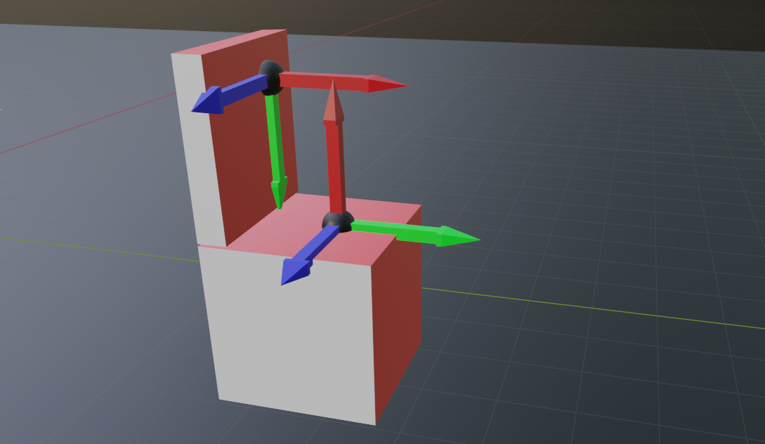
- The ParentToConstraint places the constraint at the seating point of the chair with the x axis pointing upwards of the surface and the y axis pointing to the front of the chair. This is the also the direction of the thights while sitting.
- The translation constraint has boundaries [0,0], [-side_y/2, +side_y/2], [-side_z/2, + side_z/2]
- The rotation constraint has boundaries [-90,90], [0,0], [0,0]