Tool Reference
Complete reference for all 48 built-in tools available in the FreeCAD AI Workbench. These tools are used by the LLM in Act mode (with tool calling enabled) to perform FreeCAD operations safely, with each call wrapped in an undo transaction.
Tools are organized into six categories:
- Modeling Tools -- create and modify 3D geometry
- Query Tools -- inspect and measure the model
- Utility Tools -- modify properties, export, execute code, undo
- Interactive Tools -- select geometry in the viewport
- Viewport Tools -- camera, screenshots, zoom
Create a PartDesign Body. Bodies are containers for parametric features (sketches, pads, pockets, fillets, etc.). You must create a body before using the sketch/pad/pocket workflow.
| Parameter | Type | Required | Default | Description |
|---|---|---|---|---|
label |
string | No | "Body" |
Display label for the body |
Example:
{
  "label": "EnclosureBase"
}
Notes:
- Always create a body first when using PartDesign features (sketches, pads, pockets, revolutions, lofts, sweeps).
- FreeCAD may assign a different internal Name than the label you request (e.g.,
"Body"instead of"EnclosureBase"). Tools handle this by searching both Name and Label. - For Part primitives (
create_primitive), a body is not required.
Create a Part primitive shape (Box, Cylinder, Sphere, Cone, or Torus) in the active document. These are standalone Part objects, not PartDesign features.
| Parameter | Type | Required | Default | Description |
|---|---|---|---|---|
shape_type |
string | Yes | -- | Type of primitive. One of: box, cylinder, sphere, cone, torus
|
label |
string | No | Shape type name | Display label for the object |
length |
number | No | 10.0 |
Length in mm (box only) |
width |
number | No | 10.0 |
Width in mm (box only) |
height |
number | No | 10.0 |
Height in mm (box, cylinder, cone) |
radius |
number | No | 5.0 |
Radius in mm (cylinder, sphere) or major radius (cone R1, torus R1) |
radius2 |
number | No | 2.0 |
Second radius in mm (cone R2, torus minor radius R2) |
x |
number | No | 0.0 |
X position in mm |
y |
number | No | 0.0 |
Y position in mm |
z |
number | No | 0.0 |
Z position in mm |
Example -- Box:
{
  "shape_type": "box",
  "label": "BaseBox",
  "length": 50,
  "width": 30,
  "height": 20
}
Example -- Cone:
{
  "shape_type": "cone",
  "radius": 10,
  "radius2": 3,
  "height": 25,
  "z": 5
}
Notes:
- Part primitives are standalone objects. They cannot participate in PartDesign operations (pad, pocket, fillet within a body).
- Use
boolean_operationto combine Part primitives. - For parametric modeling with sketches, use
create_body+create_sketch+pad_sketchinstead. - Position (x, y, z) sets the Placement.Base of the object.
Create a 2D sketch with geometry (lines, circles, arcs, rectangles) and constraints. Sketches are the foundation of PartDesign workflows -- they define 2D profiles that get extruded, pocketed, revolved, etc.
| Parameter | Type | Required | Default | Description |
|---|---|---|---|---|
plane |
string | No | "XY" |
Attachment plane. One of: XY, XZ, YZ
|
body_name |
string | No | "" |
Name of the PartDesign body to add the sketch to |
geometries |
array | No | [] |
List of geometry objects (see below) |
constraints |
array | No | [] |
List of Sketcher constraints (see below) |
label |
string | No | "Sketch" |
Display label for the sketch |
offset |
number | No | 0.0 |
Offset along the plane normal in mm (e.g., offset=40 on XY places the sketch at z=40) |
Each geometry object has a type field plus type-specific parameters:
Line:
{"type": "line", "x1": 0, "y1": 0, "x2": 50, "y2": 0}Rectangle (generates 4 connected lines with coincident + horizontal/vertical constraints):
{"type": "rectangle", "x": 0, "y": 0, "width": 50, "height": 30}Rectangles also accept (x1, y1, x2, y2) corner format, and length as an alias for height.
Circle:
{"type": "circle", "cx": 0, "cy": 0, "radius": 10}Also accepts "x" / "y" as aliases for "cx" / "cy".
Arc:
{"type": "arc", "cx": 0, "cy": 0, "radius": 10, "start_angle": 0, "end_angle": 3.14159}Angles are in radians. Also accepts "x" / "y" for center coordinates.
Each constraint object has a type field plus constraint-specific parameters:
{"type": "Distance", "first": 0, "value": 50.0}| Field | Description |
|---|---|
type |
Constraint type: Distance, DistanceX, DistanceY, Radius, Angle, Horizontal, Vertical, Coincident, Equal, Symmetric, Tangent, Perpendicular, Parallel, Block
|
first |
Index of the first geometry element (0-based) |
first_pos |
Point index on first element (1 = start, 2 = end, 3 = center) |
second |
Index of the second geometry element (for two-element constraints) |
second_pos |
Point index on second element |
value |
Numeric value (for dimensional constraints like Distance, Radius, Angle) |
Example -- Full sketch with constraints:
{
  "plane": "XY",
  "body_name": "Body",
  "geometries": [
    {"type": "rectangle", "x": 0, "y": 0, "width": 80, "height": 60},
    {"type": "circle", "cx": 40, "cy": 30, "radius": 5}
  ],
  "constraints": [
    {"type": "Distance", "first": 0, "value": 80.0}
  ],
  "label": "OuterProfile"
}
Notes:
- A rectangle generates 4 line geometries (indices 0-3), so subsequent geometries start at index 4.
- Always specify
body_namewhen creating sketches for PartDesign workflows. - The
offsetparameter is critical for pocket operations: placing a sketch atoffset=H(box height) allows pocketing downward into the solid to create a hollow enclosure with a floor. - Constraints with no
firstindex are silently skipped to prevent segfaults.
Pad (extrude) a sketch to create a solid feature. The sketch must be inside a PartDesign Body.
| Parameter | Type | Required | Default | Description |
|---|---|---|---|---|
sketch_name |
string | Yes | -- | Internal name of the sketch to pad |
length |
number | No | 10.0 |
Extrusion length in mm |
symmetric |
boolean | No | false |
Pad symmetrically in both directions (Midplane) |
label |
string | No | "Pad" |
Display label for the pad feature |
body_name |
string | No | "" |
Explicit body name (use when multiple bodies exist) |
Example:
{
  "sketch_name": "Sketch",
  "length": 25,
  "label": "MainPad"
}
Notes:
- The sketch is automatically hidden after padding.
- If
body_nameis omitted, the tool auto-detects the body containing the sketch. - For symmetric pads, the total height is
length(half in each direction).
Create a pocket (cut) from a sketch into the body's solid. The tool auto-detects the correct cut direction by trying both directions and keeping the one that removes the most material.
| Parameter | Type | Required | Default | Description |
|---|---|---|---|---|
sketch_name |
string | Yes | -- | Internal name of the sketch to pocket |
length |
number | No | 10.0 |
Pocket depth in mm |
through_all |
boolean | No | false |
Cut through the entire body (use only for holes; prefer explicit length for cavities) |
label |
string | No | "Pocket" |
Display label for the pocket feature |
body_name |
string | No | "" |
Explicit body name (use when multiple bodies exist) |
Example -- Hollowing an enclosure:
{
  "sketch_name": "InnerSketch",
  "length": 38,
  "label": "Cavity"
}
Notes:
-
Auto-direction detection: The tool tries both
Reversed=FalseandReversed=True, then keeps whichever direction removes more material. This handles sketches at any Z-offset correctly. -
Enclosure pattern: For hollowing a box of height H with wall thickness T, place the sketch at
offset=H(top face) with an inner rectangle at(T, T)of size(L-2T, W-2T), then pocket withlength=H-T. This leaves a floor of thickness T. - Prefer explicit
lengthoverthrough_allfor cavities to maintain floor thickness. - The sketch is automatically hidden after pocketing.
Revolve a sketch around an axis to create a solid of revolution (vases, bottles, wheels, turned parts). Uses PartDesign::Revolution (additive) or PartDesign::Groove (subtractive).
| Parameter | Type | Required | Default | Description |
|---|---|---|---|---|
sketch_name |
string | Yes | -- | Internal name of the sketch to revolve |
axis |
string | No | "Y" |
Revolution axis: X, Y, Z (origin axes) or Edge1, Edge2, etc. (sketch edge) |
angle |
number | No | 360.0 |
Revolution angle in degrees (360 = full revolution) |
subtractive |
boolean | No | false |
If true, use Groove (cut) instead of Revolution (add) |
body_name |
string | No | "" |
Explicit body name |
label |
string | No |
"Revolution" / "Groove"
|
Display label for the feature |
Example -- Wine glass profile:
{
  "sketch_name": "GlassProfile",
  "axis": "Y",
  "angle": 360,
  "label": "GlassRevolution"
}
Example -- Using a sketch edge as axis:
{
  "sketch_name": "Sketch",
  "axis": "Edge1",
  "angle": 180
}
Notes:
- When using origin axes (X, Y, Z), the tool looks up the axis from the body's Origin features.
- When using sketch edges (Edge1, Edge2, ...), the edge must be a line segment in the sketch that serves as the revolution axis. The profile geometry should be on one side of this edge.
- The sketch is automatically hidden after revolving.
Loft between two or more sketches to create a smooth transitional solid (tapered shapes, bottles, organic forms). All sketches must be in the same PartDesign Body, placed on different planes or at different offsets.
| Parameter | Type | Required | Default | Description |
|---|---|---|---|---|
section_names |
array of strings | Yes | -- | Sketch names to loft between (minimum 2, ordered from start to end) |
closed |
boolean | No | false |
Close the loft loop (connect last section back to first) |
ruled |
boolean | No | false |
Use ruled (flat) surfaces instead of smooth |
subtractive |
boolean | No | false |
If true, cut instead of add |
body_name |
string | No | "" |
Explicit body name |
label |
string | No |
"Loft" / "SubtractiveLoft"
|
Display label |
Example:
{
  "section_names": ["BottomCircle", "TopSquare"],
  "label": "TaperedTransition"
}
Notes:
- The first sketch in
section_namesbecomes theProfile, and the remaining sketches becomeSections. This matches FreeCAD's internal convention:Profile = sections[0],Sections = sections[1:]. - All section sketches must belong to the same PartDesign Body.
- Create sketches at different Z-offsets using the
offsetparameter ofcreate_sketch. - All section sketches are hidden after lofting.
Sweep a profile sketch along a spine path to create a pipe, tube, or complex swept solid. Uses PartDesign::AdditivePipe (additive) or PartDesign::SubtractivePipe (subtractive).
| Parameter | Type | Required | Default | Description |
|---|---|---|---|---|
profile_name |
string | Yes | -- | Internal name of the cross-section sketch |
spine_name |
string | Yes | -- | Internal name of the path sketch (spine) |
subtractive |
boolean | No | false |
If true, cut instead of add |
body_name |
string | No | "" |
Explicit body name |
label |
string | No |
"Sweep" / "SubtractiveSweep"
|
Display label |
Example:
{
  "profile_name": "CircleProfile",
  "spine_name": "CurvePath",
  "label": "TubeShape"
}
Notes:
- The profile sketch defines the cross-section shape that gets swept along the spine path.
- Both the profile and spine sketches must be in the same PartDesign Body.
- The profile sketch should be on a plane perpendicular to the spine at its start point.
- Both sketches are hidden after sweeping.
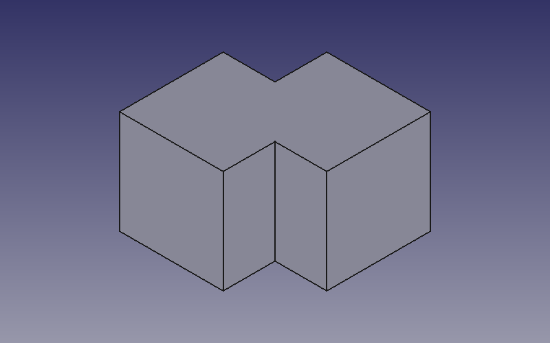
Perform a boolean operation (fuse, cut, or common/intersection) between two Part objects. Uses Part::Fuse, Part::Cut, or Part::Common.
| Parameter | Type | Required | Default | Description |
|---|---|---|---|---|
operation |
string | Yes | -- | Operation type. One of: fuse, cut, common
|
object1 |
string | Yes | -- | Internal name of the first object (base for cut) |
object2 |
string | Yes | -- | Internal name of the second object (tool for cut) |
label |
string | No | Operation name | Display label for the result |
Example:
{
  "operation": "cut",
  "object1": "MainBox",
  "object2": "HoleCylinder",
  "label": "BoxWithHole"
}
Notes:
- Boolean operations work with Part objects (primitives, Part features). They do not work directly with PartDesign bodies.
- For
cut:object1is the base (kept),object2is the tool (subtracted). - The underlying Part objects use
.Baseand.Toolproperties (not.Shape1/.Shape2). - The original objects remain in the document but are typically hidden.
Move and/or rotate an object by setting its Placement. This replaces the entire Placement (it does not add to the existing placement).
| Parameter | Type | Required | Default | Description |
|---|---|---|---|---|
object_name |
string | Yes | -- | Internal name of the object to transform |
translate_x |
number | No | 0.0 |
X translation in mm |
translate_y |
number | No | 0.0 |
Y translation in mm |
translate_z |
number | No | 0.0 |
Z translation in mm |
rotate_axis_x |
number | No | 0.0 |
Rotation axis X component |
rotate_axis_y |
number | No | 0.0 |
Rotation axis Y component |
rotate_axis_z |
number | No | 1.0 |
Rotation axis Z component |
rotate_angle |
number | No | 0.0 |
Rotation angle in degrees |
Example -- Position a lid:
{
  "object_name": "EnclosureLid",
  "translate_z": 37
}
Example -- Rotate 45 degrees around Z:
{
  "object_name": "Part",
  "rotate_axis_z": 1,
  "rotate_angle": 45
}
Notes:
- This tool replaces the object's Placement entirely. If the object already has a placement, it will be overwritten.
- The rotation axis vector does not need to be normalized; FreeCAD normalizes it internally.
- Default rotation axis is Z (0, 0, 1). Change the axis components for rotations around other axes.
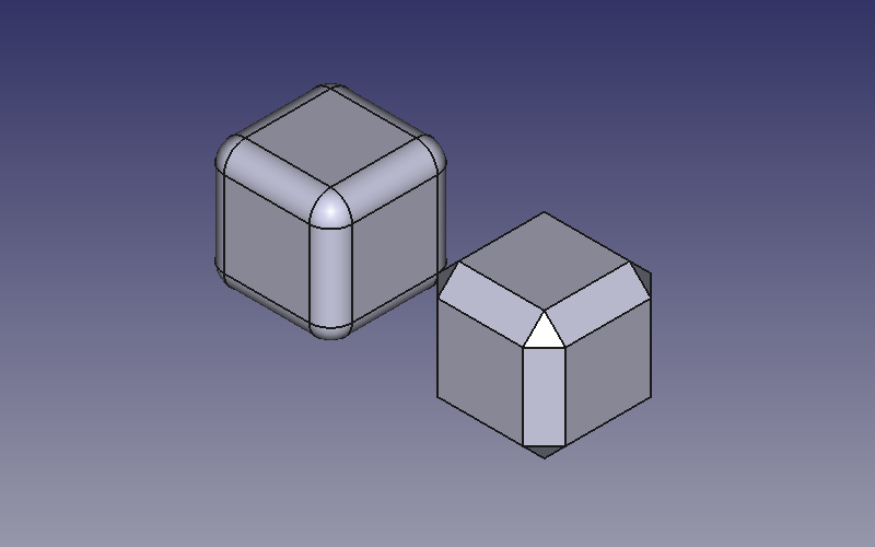
Apply a fillet (rounded edge) to one or more edges of an object. Works with both PartDesign features (creates PartDesign::Fillet inside the body) and Part objects (creates Part::Fillet). When called with a Body as object_name, automatically uses the Body's Tip feature.
| Parameter | Type | Required | Default | Description |
|---|---|---|---|---|
object_name |
string | Yes | -- | Internal name of the object or Body |
edges |
array of strings | No | ["Edge1"] |
Edge references or filter keywords |
radius |
number | No | 1.0 |
Fillet radius in mm |
label |
string | No | "Fillet" |
Display label |
Filter keywords for edges: "all", "vertical", "horizontal", "top", "bottom", "front", "back", "left", "right", "circular". Filters can be combined (union): ["top", "vertical"]. Can also mix with explicit names: ["Edge1", "vertical"].
Examples:
{
  "object_name": "BoxBody",
  "edges": ["all"],
  "radius": 2.0
}
{
"object_name": "Pad",
"edges": ["vertical"],
"radius": 1.0,
"label": "VerticalFillets"
}Notes:
- Use
list_edgesto discover available edge names and their labels (vertical, top-front, etc.). - Edge numbering in FreeCAD is 1-based:
Edge1,Edge2, etc. - For PartDesign objects, the fillet is added as a new feature inside the body chain.
- If the fillet radius is too large for the geometry, FreeCAD will report an error and the operation will be rolled back.
Apply a chamfer (angled edge cut) to one or more edges of an object. Works with both PartDesign and Part objects. Supports the same filter keywords as fillet_edges.
| Parameter | Type | Required | Default | Description |
|---|---|---|---|---|
object_name |
string | Yes | -- | Internal name of the object or Body |
edges |
array of strings | No | ["Edge1"] |
Edge references or filter keywords (same as fillet_edges) |
size |
number | No | 1.0 |
Chamfer size in mm |
label |
string | No | "Chamfer" |
Display label |
Example:
{
  "object_name": "Pad",
  "edges": ["bottom"],
  "size": 1.5,
  "label": "BottomChamfers"
}
Notes:
- Same edge discovery process as fillets: use
measurewithmeasure_type: "edges"first. - The chamfer is symmetric (equal distance on both faces meeting at the edge).
Hollow out a solid by removing selected faces and applying a wall thickness. Uses PartDesign::Thickness internally. The object must be inside a PartDesign Body.
| Parameter | Type | Required | Default | Description |
|---|---|---|---|---|
object_name |
string | Yes | -- | Internal name of the solid object to shell |
faces |
array of strings | No | -- | Face references to remove, e.g. ["Face1", "Face6"]
|
thickness |
number | No | 1.0 |
Wall thickness in mm |
join |
string | No | "Arc" |
Join type for corners. One of: Arc, Intersection
|
reversed |
boolean | No | true |
Shell direction: true = inward (preserves outer dimensions), false = outward |
label |
string | No | "" |
Display label for the shell feature |
Example -- Hollow a box keeping the top face open:
{
  "object_name": "Pad",
  "faces": ["Face6"],
  "thickness": 2.0,
  "label": "ShellWalls"
}
Notes:
- The object must be a PartDesign feature inside a Body (not a standalone Part::Feature).
-
reversed=true(the default) shells inward, preserving the outer dimensions of the solid. Usefalseto grow outward. - Use the
measuretool withmeasure_type: "edges"orget_document_stateto discover face names before shelling.
Repeat a PartDesign feature in a linear pattern along an axis. The feature must be inside a PartDesign Body.
| Parameter | Type | Required | Default | Description |
|---|---|---|---|---|
feature_name |
string | Yes | -- | Internal name of the feature to repeat |
direction |
string | No | "X" |
Pattern direction: X, Y, Z (origin axes) or Sketch.Edge1 (sketch edge reference) |
length |
number | Yes | -- | Total span of the pattern in mm |
occurrences |
integer | Yes | -- | Number of occurrences (including the original) |
label |
string | No | "" |
Display label for the pattern |
Example -- 4 mounting holes along X:
{
  "feature_name": "MountingHole",
  "direction": "X",
  "length": 60,
  "occurrences": 4,
  "label": "MountingHolePattern"
}
Notes:
- The feature must be inside a PartDesign Body.
-
occurrencesincludes the original feature. Sooccurrences: 4withlength: 60places copies at 0, 20, 40, and 60mm. - Supports origin axes (
X,Y,Z) or sketch edge references (format:Sketch.Edge1).
Repeat a PartDesign feature in a circular pattern around an axis. The feature must be inside a PartDesign Body.
| Parameter | Type | Required | Default | Description |
|---|---|---|---|---|
feature_name |
string | Yes | -- | Internal name of the feature to repeat |
axis |
string | No | "Z" |
Rotation axis: X, Y, Z (origin axes) or Sketch.Edge1 (sketch edge reference) |
angle |
number | No | 360.0 |
Total angular span in degrees (360 = full circle) |
occurrences |
integer | Yes | -- | Number of occurrences (including the original) |
label |
string | No | "" |
Display label for the pattern |
Example -- 6 bolt holes around Z:
{
  "feature_name": "BoltHole",
  "axis": "Z",
  "angle": 360,
  "occurrences": 6,
  "label": "BoltCircle"
}
Notes:
- The feature must be inside a PartDesign Body.
-
occurrencesincludes the original.occurrences: 6withangle: 360places copies every 60 degrees. - An
angleless than 360 distributes copies over a partial arc.
Mirror a PartDesign feature across a plane. The feature must be an additive (Pad, Loft, etc.) or subtractive (Pocket, Groove, etc.) feature inside a Body.
| Parameter | Type | Required | Default | Description |
|---|---|---|---|---|
feature_name |
string | Yes | -- | Internal name of the feature to mirror |
plane |
string | No | "YZ" |
Mirror plane: XY, XZ, YZ (origin planes) or Sketch.N_Axis (sketch axis) |
label |
string | No | "" |
Display label for the mirror |
Example -- Mirror a boss across YZ plane:
{
  "feature_name": "MountBoss",
  "plane": "YZ",
  "label": "MirroredBoss"
}
Notes:
- Only additive/subtractive features can be mirrored. Transformation features (Mirrored, LinearPattern, PolarPattern) cannot be mirrored -- mirror the original feature instead.
- Uses PartDesign::Mirrored internally.
Chain multiple transformation steps (linear pattern, polar pattern, mirror) into a single PartDesign::MultiTransform feature. Accepts one or more source features -- pass related features (e.g., a post and its screw hole) together so they are transformed as a group.
| Parameter | Type | Required | Default | Description |
|---|---|---|---|---|
feature_names |
array of strings | Yes | -- | Feature(s) to transform. Order matters: the last feature should be the most recent in the model tree. Pass multiple related features to transform them as a group. |
transformations |
array of objects | Yes | -- | List of transformation steps (see below) |
label |
string | No | "" |
Display label for the MultiTransform |
Transformation step objects:
| Type | Fields |
|---|---|
linear_pattern |
direction (X/Y/Z), length, occurrences
|
polar_pattern |
axis (X/Y/Z), angle, occurrences
|
mirror |
plane (XY/XZ/YZ) |
Example -- Mirror then repeat linearly:
{
  "feature_names": ["ScrewPost"],
  "transformations": [
    {"type": "mirror", "plane": "YZ"},
    {"type": "linear_pattern", "direction": "Y", "length": 40, "occurrences": 3}
  ],
  "label": "PostArray"
}
Notes:
- All features must be additive or subtractive features in the same Body. Transformation features cannot be used as input.
- More efficient and cleaner than stacking separate pattern/mirror features.
- The source features are hidden; the MultiTransform feature is visible.
Scale an object uniformly or non-uniformly. Works on Part objects (not PartDesign bodies).
| Parameter | Type | Required | Default | Description |
|---|---|---|---|---|
object_name |
string | Yes | -- | Internal name of the object to scale |
scale_x |
number | No | 1.0 |
X scale factor |
scale_y |
number | No | 1.0 |
Y scale factor |
scale_z |
number | No | 1.0 |
Z scale factor |
uniform |
number | No | 0.0 |
Uniform scale factor (overrides x/y/z if non-zero) |
copy |
boolean | No | false |
Create a scaled copy instead of modifying in-place |
label |
string | No | "" |
Label for the copy (only used when copy=true) |
Example -- Scale uniformly to 150%:
{
  "object_name": "Part",
  "uniform": 1.5
}
Example -- Non-uniform scale with copy:
{
  "object_name": "Part",
  "scale_x": 2.0,
  "scale_z": 0.5,
  "copy": true,
  "label": "StretchedCopy"
}
Notes:
- Works on Part objects only, not PartDesign Bodies.
- If
uniformis non-zero, it overrides the individualscale_x/scale_y/scale_zvalues. - Uses
shape.transformGeometry()internally.
Create a cross-section of an object: either cut with a plane (XY/XZ/YZ at a given offset) or intersect two shapes.
| Parameter | Type | Required | Default | Description |
|---|---|---|---|---|
object_name |
string | Yes | -- | Internal name of the object to section |
tool_object |
string | No | "" |
Second object for shape-vs-shape section (omit for plane section) |
plane |
string | No | "XY" |
Section plane (used when tool_object is omitted). One of: XY, XZ, YZ
|
offset |
number | No | 0.0 |
Offset along the plane normal (e.g., z-height for XY plane) |
label |
string | No | "" |
Display label for the section |
Example -- Horizontal cross-section at z=15:
{
  "object_name": "Pad",
  "plane": "XY",
  "offset": 15,
  "label": "MidSection"
}
Example -- Intersect two shapes:
{
  "object_name": "Body1",
  "tool_object": "Body2",
  "label": "Intersection"
}
Notes:
- Two modes: plane section (default) cuts the object with an infinite plane; shape-vs-shape intersects with another object.
- Returns edge count and bounding box in the result data.
Create a PartDesign wedge (tapered box) inside a Body via loft. The base face is length x width, the top face is top_length x top_width (centered). Default top_width=0 creates a classic ramp/wedge shape tapering to a ridge. Compatible with fillet, chamfer, shell, pattern, and mirror.
| Parameter | Type | Required | Default | Description |
|---|---|---|---|---|
length |
number | No | 10.0 |
Base length (X dimension) in mm |
width |
number | No | 10.0 |
Base width (Y dimension) in mm |
height |
number | No | 10.0 |
Height (Z dimension) in mm |
top_length |
number | No | Same as length
|
Top face length (no taper in X if equal to base) |
top_width |
number | No | 0 |
Top face width (0 = taper to ridge) |
label |
string | No | "" |
Display label |
body_name |
string | No | "" |
Name of existing Body to add to (auto-creates if empty) |
operation |
string | No | "additive" |
additive (add material) or subtractive (cut material) |
x |
number | No | 0.0 |
X position in mm |
y |
number | No | 0.0 |
Y position in mm |
z |
number | No | 0.0 |
Z position in mm |
Example -- Ramp tapering to a ridge:
{
  "length": 30,
  "width": 20,
  "height": 15,
  "label": "Ramp"
}
Example -- Truncated pyramid:
{
  "length": 40,
  "width": 40,
  "height": 25,
  "top_length": 20,
  "top_width": 20,
  "label": "Pyramid"
}
Notes:
- Internally creates a PartDesign loft between two rectangular sketches (base and top).
- Default
top_width=0tapers the Y dimension to zero, producing a classic wedge/ramp shape. - Set
top_lengthandtop_widthto smaller values for a truncated pyramid. - Both construction sketches are auto-hidden after creation.
Add a thin ridge/ledge running around the inside perimeter of a rectangular hollow body. This is designed for snap-fit enclosure lids -- the ridge acts as a catch that the lid's snap tabs hook onto.
| Parameter | Type | Required | Default | Description |
|---|---|---|---|---|
body_name |
string | Yes | -- | Name of the PartDesign body to add the ridge to |
length |
number | Yes | -- | Outer length of the enclosure (L) in mm |
width |
number | Yes | -- | Outer width of the enclosure (W) in mm |
wall_thickness |
number | Yes | -- | Wall thickness (T) in mm -- must match the enclosure |
ridge_width |
number | No | 0.8 |
Inward protrusion from wall in mm. Default is tuned for 3D printing |
ridge_height |
number | No | 0.5 |
Height along Z in mm. Default is tuned for 3D printing |
z_position |
number | Yes | -- | Z height where the ridge starts (typically H-2 for a 3mm lip) |
label |
string | No | "Ridge" |
Display label |
Example:
{
  "body_name": "EnclosureBase",
  "length": 80,
  "width": 60,
  "wall_thickness": 2,
  "z_position": 38,
  "label": "SnapRidge"
}
Notes:
- The ridge is created as a ring-shaped pad (outer rectangle minus inner rectangle) at the specified Z position.
- Default dimensions (0.8mm wide, 0.5mm tall) are optimized for FDM 3D printing. Do not override unless the user specifically requests different values.
- The ridge should be placed 1-2mm below the top of the enclosure wall (e.g.,
z_position = H - 2for a 3mm lid lip).
Add snap tabs on the outside of a rectangular lid lip. The tabs catch on an inner ridge (created by create_inner_ridge) to hold the lid in place. Places 2 tabs on each long side and 1 on each short side (6 tabs total).
| Parameter | Type | Required | Default | Description |
|---|---|---|---|---|
body_name |
string | Yes | -- | Name of the lid body with the lip |
length |
number | Yes | -- | Outer length of the enclosure (L) in mm |
width |
number | Yes | -- | Outer width of the enclosure (W) in mm |
wall_thickness |
number | Yes | -- | Wall thickness (T) in mm -- must match the enclosure |
clearance |
number | No | 0.2 |
Gap between lip and wall in mm. Use 1.0 for snap-fit |
lip_height |
number | No | 3.0 |
Height of the lip in mm |
tab_width |
number | No | 3.0 |
Width of each tab along the wall in mm |
tab_height |
number | No | 1.0 |
Height of each tab along Z in mm |
protrusion |
number | No | 0.5 |
How far each tab protrudes outward in mm |
label |
string | No | "SnapTab" |
Display label for the result |
Example:
{
  "body_name": "EnclosureLid",
  "length": 80,
  "width": 60,
  "wall_thickness": 2,
  "clearance": 1.0,
  "label": "SnapTabs"
}
Notes:
- The lid must be built lip-first (lip at body origin, slab on top) and positioned with
transform_objectbefore calling this tool. - The tool creates a new
Part::Featurethat replaces the visual representation of the body (the body is hidden). - Protrusion is automatically clamped to
clearance - 0.05mmto prevent tabs from penetrating the base wall. - Minimum clearance for snap tabs is approximately 0.5mm. The tool returns an error if clearance is too small.
- Tab placement: 2 tabs evenly spaced on each long side (Y-axis walls), 1 tab centered on each short side (X-axis walls).
Create a complete snap-fit enclosure lid with correct lip + slab geometry in a single tool call. This eliminates the need for manual arithmetic to compute lip insets and clearances.
| Parameter | Type | Required | Default | Description |
|---|---|---|---|---|
length |
number | Yes | -- | Outer length of the enclosure (L) in mm |
width |
number | Yes | -- | Outer width of the enclosure (W) in mm |
wall_thickness |
number | Yes | -- | Wall thickness (T) in mm -- must match the base |
clearance |
number | No | 1.0 |
Gap between lip and cavity wall in mm. Use 1.0 for snap-fit |
lip_height |
number | No | 3.0 |
How far the lip extends down into the base in mm |
label |
string | No | "EnclosureLid" |
Display label for the lid body |
Example:
{
  "length": 80,
  "width": 60,
  "wall_thickness": 2,
  "clearance": 1.0,
  "lip_height": 3,
  "label": "Lid"
}
What it creates:
- A new PartDesign Body.
- A lip pad: rectangle inset by
T + clearancefrom each edge, extrudedlip_heightmm. - A slab pad: full
length x widthrectangle on top of the lip, extrudedTmm (wall thickness).
After calling this tool:
- Position the lid with
transform_objectattranslate_z = H - lip_height(where H is the enclosure height). - Add snap tabs with
create_snap_tabs.
Notes:
- The lip is automatically inset by
wall_thickness + clearanceso it fits inside the base cavity. - The slab sits on top of the lip and covers the full enclosure footprint.
- This tool was created to prevent LLM arithmetic errors when computing lip dimensions manually.
Create an Assembly container and add existing bodies/parts to it. The first part is automatically grounded (fixed reference frame) so the solver has a stable base.
| Parameter | Type | Required | Default | Description |
|---|---|---|---|---|
label |
string | No | "Assembly" |
Display label for the assembly |
part_names |
array | No | [] |
List of body/part names to include |
ground_first |
boolean | No | true |
Ground the first part as fixed reference |
Example:
{
  "label": "MechanismAssembly",
  "part_names": ["BasePlate", "HingeBlock", "Arm"]
}
Notes:
- Creates an
Assembly::AssemblyObjectwith aJointGroupfor joints. - The grounded part does not move when joints are solved.
- Returns the assembly name to use with
add_assembly_joint.
Add a joint between two parts in an assembly. The second part is repositioned by the native FreeCAD solver so its face meets the first part's face.
| Parameter | Type | Required | Default | Description |
|---|---|---|---|---|
assembly_name |
string | Yes | -- | Name of the assembly (from create_assembly) |
part1_name |
string | Yes | -- | Name of the reference part |
face1 |
string | Yes | -- | Face on part1 (e.g. "Face6") |
part2_name |
string | Yes | -- | Name of the part to position |
face2 |
string | Yes | -- | Face on part2 to mate with face1 |
joint_type |
string | No | "Fixed" |
Joint type (see below) |
label |
string | No | auto | Display label for the joint |
Joint types:
| Type | DOFs | Description | Face selection |
|---|---|---|---|
Fixed |
0 | Parts locked together | Top + bottom (stacking) or side + side |
Revolute |
1 rotation | Hinge | Side face of mount + end face of arm |
Cylindrical |
1 rotation + 1 translation | Peg-in-hole | Curved face of cylinder + hole face |
Slider |
1 translation | Linear slide | Parallel faces |
Ball |
3 rotations | Ball-and-socket | Spherical faces (see warning) |
Example -- Fixed joint (stacking):
{
  "assembly_name": "MyAssembly",
  "part1_name": "BasePlate",
  "face1": "Face6",
  "part2_name": "Pillar",
  "face2": "Face5",
  "joint_type": "Fixed"
}
Example -- Revolute joint (hinge):
{
  "assembly_name": "MyAssembly",
  "part1_name": "HingeBlock",
  "face1": "Face4",
  "part2_name": "Arm",
  "face2": "Face3",
  "joint_type": "Revolute",
  "label": "HingeJoint"
}
Notes:
- Always use
list_facesfirst to identify the correct face names and normals. - The rotation axis for Revolute/Cylindrical joints is the face normal. Use side faces (X/Y normal) for horizontal hinges, top/bottom faces (Z normal) for turntables.
- For Revolute joints, connect a side face of the mount to an end face of the arm so the arm extends outward.
⚠️ Ball joint warning: Ball joints require spherical geometry — one part must have an additive sphere (ball) and the other a subtractive sphere (socket). Connecting flat box faces with a Ball joint will not produce correct results. Additionally, the ball-and-socket geometry must be designed with enough clearance to avoid intersections with other features (posts, plates). This is a FreeCAD Assembly workbench requirement, not a limitation of this tool.
Add an existing part/body to an assembly, optionally at a specific position.
| Parameter | Type | Required | Default | Description |
|---|---|---|---|---|
assembly_name |
string | Yes | -- | Name of the assembly |
part_name |
string | Yes | -- | Name of the part to add |
position |
array | No | null |
Position as [x, y, z] in mm |
Example:
{
  "assembly_name": "MyAssembly",
  "part_name": "NewPart",
  "position": [50, 0, 0]
}Measure properties of objects: volume, surface area, bounding box, center-to-center distance between objects, or list all edge names.
| Parameter | Type | Required | Default | Description |
|---|---|---|---|---|
measure_type |
string | Yes | -- | What to measure. One of: volume, area, bbox, distance, edges
|
target |
string | Yes | -- | Internal name of the object to measure |
target2 |
string | No | "" |
Second object name (required for distance measurements) |
Example -- Get bounding box:
{
  "measure_type": "bbox",
  "target": "Pad"
}
Returns: Bounding box of 'Pad': X[0.0, 50.0] Y[0.0, 30.0] Z[0.0, 20.0] Size: 50.0 x 30.0 x 20.0mm
Example -- List edges (for fillet/chamfer):
{
  "measure_type": "edges",
  "target": "Pad"
}
Returns: 'Pad' has 12 edges: Edge1, Edge2, Edge3, Edge4, Edge5, Edge6, Edge7, Edge8, Edge9, Edge10, Edge11, Edge12
Example -- Distance between objects:
{
  "measure_type": "distance",
  "target": "Box1",
  "target2": "Cylinder1"
}
Returns: Distance between bounding box centers of the two objects.
Measure types:
| Type | Output | Data Fields |
|---|---|---|
volume |
Volume in mm^3 | volume |
area |
Surface area in mm^2 | area |
bbox |
Bounding box min/max/size |
xmin, xmax, ymin, ymax, zmin, zmax, size_x, size_y, size_z
|
distance |
Center-to-center distance in mm | distance |
edges |
Edge count and names |
edge_count, edges (array) |
Notes:
- The
edgesmeasure type is especially useful before callingfillet_edgesorchamfer_edges, so the LLM knows which edge names to reference. - Distance measurement uses bounding box centers, not closest-point distance.
Get the current document state including all objects, their types, labels, and key properties. Takes no parameters.
| Parameter | Type | Required | Default | Description |
|---|---|---|---|---|
| (none) | -- | -- | -- | This tool takes no parameters |
Example:
{}Notes:
- Returns a text summary of all objects in the active document, including their types (e.g.,
Part::Box,PartDesign::Body,Sketcher::SketchObject), labels, and key geometric properties. - The LLM calls this to understand what already exists in the document before making modifications.
- Returns "No document is open, or the document is empty." if no document is active.
- This information is also automatically included in the system prompt with each message, so explicit calls are mainly useful after multi-step operations to verify intermediate state.
List all faces of an object with reference names, human-readable labels, center positions, normals, and areas. Optional filter to show only matching faces.
| Parameter | Type | Required | Default | Description |
|---|---|---|---|---|
object_name |
string | Yes | -- | Internal name or label of the object |
filter |
string | No | "" |
Filter keyword (e.g. "top", "cylindrical", "side") |
Example:
{
  "object_name": "BoxBody",
  "filter": "top"
}
Returns:
## Faces of 'BoxBody' matching 'top' (1/6 faces)
- **Face6** "top" — center=(25.0, 15.0, 20.0), area=1500.0mm²  normal=(0.00, 0.00, 1.00)
Notes:
- Face labels:
top,bottom,front,back,left,right,side,cylindrical,spherical,conical,toroidal,angled. - Use before
shell_objectto identify which faces to remove, or beforeadd_assembly_jointfor joint setup.
List all edges of an object with reference names, human-readable labels, midpoint positions, and lengths. Optional filter to show only matching edges.
| Parameter | Type | Required | Default | Description |
|---|---|---|---|---|
object_name |
string | Yes | -- | Internal name or label of the object |
filter |
string | No | "" |
Filter keyword (e.g. "vertical", "top", "circular") |
Example:
{
  "object_name": "BoxBody",
  "filter": "vertical"
}
Returns:
## Edges of 'BoxBody' matching 'vertical' (4/12 edges)
- **Edge1** "front-left vertical" — midpoint=(0.0, 0.0, 10.0), length=20.0mm
- **Edge3** "back-left vertical" — midpoint=(0.0, 30.0, 10.0), length=20.0mm
...
Notes:
- Edge labels:
vertical,horizontal-X,horizontal-Y,horizontal,diagonal,circular,spline,elliptical. - Position prefixes:
top,bottom,front,back,left,right,interior. - Use before
fillet_edgesorchamfer_edgesto identify edge names. The same filter keywords work in both tools.
List all open FreeCAD documents with object counts, active indicator, modified flag, and file path.
| Parameter | Type | Required | Default | Description |
|---|---|---|---|---|
| (none) | -- | -- | -- | This tool takes no parameters |
Example:
{}Returns:
## Open Documents (2)
- **Unnamed** (active) * — 5 objects — (unsaved)
- **MyProject** — 12 objects — /home/user/MyProject.FCStd
Switch the active FreeCAD document by name or label. All subsequent tool calls will operate on the new active document.
| Parameter | Type | Required | Default | Description |
|---|---|---|---|---|
document_name |
string | Yes | -- | Name or label of the document to activate |
Example:
{
  "document_name": "MyProject"
}Comprehensive geometry summary of an object in one call: bounding box, volume, face/edge counts, hollow/solid detection, estimated wall thickness, and PartDesign feature list.
| Parameter | Type | Required | Default | Description |
|---|---|---|---|---|
object_name |
string | Yes | -- | Internal name or label of the object |
Example:
{
  "object_name": "EnclosureBase"
}Load a skill's detailed instructions for a complex task. The model calls this autonomously when the user's request matches a skill (e.g., "create an enclosure"). The skill content (SKILL.md) is returned as the tool result, and the model follows the instructions step by step.
| Parameter | Type | Required | Default | Description |
|---|---|---|---|---|
name |
string | Yes | -- | Skill name (e.g. enclosure, gear, fastener-hole) |
args |
string | No | "" |
User's parameters for the skill (e.g. 120x80x60mm, screw lid) |
Example:
{"name": "enclosure", "args": "120x80x60mm, snap-fit lid"}Notes:
- The model decides autonomously when to invoke a skill — users don't need to type slash commands.
- The skill's SKILL.md content is returned as the tool result. The model reads it and follows the step-by-step construction guide.
- Users can still invoke skills directly with slash commands (e.g.,
/enclosure 120x80x60mm). - If a skill has a
handler.py, it runs the handler instead of returning SKILL.md content.
Report the parameters used for the current skill execution. Called by the LLM at the end of a skill run so the system can validate the geometry result with --validate.
| Parameter | Type | Required | Default | Description |
|---|---|---|---|---|
params |
object | Yes | -- | Dict of parameter names and values used (e.g., {"L": 100, "W": 80, "H": 40}) |
Example:
{"params": {"L": 100, "W": 80, "H": 40, "T": 2, "lid_type": "screw"}}Notes:
- This tool is called by the LLM at the end of a skill execution to report what parameter values were used.
- The stored parameters are consumed by the
--validateflag to check geometry correctness against the skill'sVALIDATION.mdrules. - Skills should include an instruction in their Critical Rules section telling the LLM to call this tool after completing all construction steps.
- Parameters are stored until consumed by validation or cleared on the next invocation.
Modify any property on a document object. This is a general-purpose tool for changing object properties that are not covered by other specific tools.
| Parameter | Type | Required | Default | Description |
|---|---|---|---|---|
object_name |
string | Yes | -- | Internal name of the object |
property_name |
string | Yes | -- | Name of the property to modify |
value |
string/number/boolean | Yes | -- | New value for the property |
Example -- Change box height:
{
  "object_name": "Box",
  "property_name": "Height",
  "value": 30
}
Example -- Hide an object:
{
  "object_name": "Sketch",
  "property_name": "Visibility",
  "value": false
}
Example -- Change label:
{
  "object_name": "Body",
  "property_name": "Label",
  "value": "EnclosureBase"
}
Example -- Relative modification (increase by 10%):
{
  "object_name": "Pad",
  "property_name": "Length",
  "value": "+10%"
}
Notes:
- The property must exist on the object. Common properties include:
Length,Width,Height,Radius,Label,Visibility,Placement. - Supports relative expressions:
"+10%","-20%","*1.5","+5","-3". Reports old→new value. - Numbers and booleans are passed directly. For complex property types (Placement, Vector), use
execute_codeinstead.
Create an App::VarSet with named, typed variables for parametric modeling. Variables appear as editable properties in the Data panel.
| Parameter | Type | Required | Default | Description |
|---|---|---|---|---|
variables |
object | Yes | -- | Dict of variable names and values |
label |
string | No | "Variables" |
Display label |
Example:
{
  "variables": {"length": 50, "width": 30, "height": 20, "wall": 2},
  "label": "Dimensions"
}
Notes:
- After creation, pass variable references as dimensions in
create_sketch(e.g.width="Dimensions.length") andpad_sketch(e.g.length="Dimensions.height"). - The user can modify dimensions by selecting the VarSet in the model tree and editing properties in the Data panel.
- Variable types are auto-detected:
float,int,str,bool.
Create a Spreadsheet::Sheet with named cell aliases for parametric modeling. An alternative to create_variable_set — variables are stored as named cells editable in the Spreadsheet workbench.
| Parameter | Type | Required | Default | Description |
|---|---|---|---|---|
variables |
object | Yes | -- | Dict of variable names and values |
label |
string | No | "Variables" |
Display label |
Example:
{
  "variables": {"length": 50, "width": 30, "height": 20},
  "label": "BoxDimensions"
}
Notes:
- Works identically to
create_variable_setfor expression references (BoxDimensions.length). - Supports formulas in cells (e.g.
=A1*2) when edited in the Spreadsheet workbench. - Avoid variable names that look like cell addresses (A1, B2, etc.).
Bind an object property to an expression for parametric relationships. Use with create_variable_set or create_spreadsheet to make models parametric.
| Parameter | Type | Required | Default | Description |
|---|---|---|---|---|
object_name |
string | Yes | -- | Internal name of the object |
property_name |
string | Yes | -- | Property to bind (e.g. Length, Constraints[3]) |
expression |
string | Yes | -- | Expression string (empty to clear) |
Examples:
{
  "object_name": "Pad",
  "property_name": "Length",
  "expression": "Variables.height"
}
{
"object_name": "Sketch",
"property_name": "Constraints[4]",
"expression": "Variables.width * 2"
}Notes:
- Supports indexed properties (
Constraints[N]) and nested properties (Placement.Base.x). - Preferred approach: pass expression strings directly in
create_sketchandpad_sketchinstead of usingset_expressionseparately. - Pass empty string as
expressionto clear the binding.
Export objects to a file in STL, STEP, or IGES format.
| Parameter | Type | Required | Default | Description |
|---|---|---|---|---|
format |
string | Yes | -- | Export format. One of: stl, step, iges
|
filename |
string | Yes | -- | Output file path (absolute or relative to FreeCAD's working directory) |
objects |
array of strings | No | All objects with shapes | Object names to export. If omitted, exports all objects that have a Shape. |
Example -- Export to STL:
{
  "format": "stl",
  "filename": "/home/user/enclosure_base.stl"
}
Example -- Export specific objects to STEP:
{
  "format": "step",
  "filename": "/tmp/lid.step",
  "objects": ["EnclosureLid"]
}
Notes:
- STL export uses
Mesh.export(), which tessellates the geometry. Good for 3D printing. - STEP and IGES export use
Part.export(), which preserves exact geometry. Good for CAD interchange. - If
objectsis omitted, all objects in the document that have aShapeattribute are exported.
Run arbitrary Python code in FreeCAD's Python interpreter. This is the fallback tool for operations not covered by structured tools.
| Parameter | Type | Required | Default | Description |
|---|---|---|---|---|
code |
string | Yes | -- | Python code to execute |
Example -- Hide all sketches:
{
  "code": "import FreeCAD as App\nfor obj in App.ActiveDocument.Objects:\n    if obj.TypeId == 'Sketcher::SketchObject':\n        obj.Visibility = False"
}
Example -- Add a custom property:
{
  "code": "import FreeCAD as App\nobj = App.ActiveDocument.getObject('Body')\nobj.addProperty('App::PropertyString', 'PartNumber', 'Custom', 'Part number')\nobj.PartNumber = 'ENC-001'"
}
Notes:
- The code has access to all standard FreeCAD modules:
FreeCAD(asApp),FreeCADGui(asGui),Part,PartDesign,Sketcher,Draft,Mesh. - Standard output (
print()) is captured and returned in the tool result. - Errors (exceptions) are caught and returned as the error field.
- This tool is not wrapped in an undo transaction by default. The code itself should manage undo if needed.
- Use this tool as a last resort when no structured tool covers the operation.
Undo operations in the active document. Supports undoing by step count or by transaction name.
| Parameter | Type | Required | Default | Description |
|---|---|---|---|---|
steps |
integer | No | 1 |
Number of operations to undo |
until |
string | No | "" |
Undo back to this named transaction (substring match, overrides steps) |
Examples:
{"steps": 3}{"until": "Pocket"}Notes:
- Each tool call creates a named undo transaction (e.g., "Pad Sketch", "Create Body").
- The
untilparameter does a case-insensitive substring match on transaction names."pocket"matches "Pocket Sketch". - Returns what was undone, plus remaining undo/redo counts.
- The actual number of undo steps is clamped to the available undo count.
Redo previously undone operations.
| Parameter | Type | Required | Default | Description |
|---|---|---|---|---|
steps |
integer | No | 1 |
Number of operations to redo |
Example:
{"steps": 1}Notes:
- Returns what was redone.
- The redo stack is cleared when new operations are performed after an undo.
Show the undo/redo stack with named transactions. Use this to see what can be undone or redone before deciding.
No parameters.
Example output:
**Undo stack (5):** (most recent first)
  1. Create Snap Tabs
  2. Pad Sketch
  3. Create Sketch
  4. Pocket Sketch
  5. Pad Sketch
**Redo stack (2):**
  1. Create Inner Ridge
  2. Transform Object
Ask the user to select geometry (edges, faces, vertices) in the 3D viewport. Opens an interactive selection panel and waits for the user to click on geometry and press Done. Useful when the LLM needs the user to identify specific edges for filleting, faces for shelling, etc.
| Parameter | Type | Required | Default | Description |
|---|---|---|---|---|
prompt |
string | No | "Select geometry" |
Instruction shown to the user, e.g., "Select edges to fillet"
|
select_type |
string | No | "any" |
Type of geometry to accept. One of: any, edge, face, vertex
|
max_count |
integer | No | 0 |
Maximum number of selections (0 = unlimited) |
Example -- Ask user to pick edges:
{
  "prompt": "Select edges to fillet",
  "select_type": "edge"
}
Example -- Ask user to pick a single face:
{
  "prompt": "Click the face to remove for shelling",
  "select_type": "face",
  "max_count": 1
}
Notes:
- This is an interactive tool that pauses execution until the user completes the selection (or cancels).
- Returns a list of selections, each containing the object name, sub-element reference (e.g.,
"Edge3","Face1"), and 3D coordinates. - If the user cancels, the result contains an empty selections list (still
success: true). - The LLM can use the returned sub-element names directly in subsequent tool calls (e.g., passing edge names to
fillet_edges).
Save a screenshot of the 3D viewport to a file.
| Parameter | Type | Required | Default | Description |
|---|---|---|---|---|
filepath |
string | Yes | -- | Output file path (e.g., /tmp/screenshot.png) |
width |
integer | No | 800 |
Image width in pixels |
height |
integer | No | 600 |
Image height in pixels |
background |
string | No | "Current" |
Background color. One of: Current, White, Black, Transparent
|
Example:
{
  "filepath": "/tmp/enclosure.png",
  "width": 1024,
  "height": 768,
  "background": "White"
}
Notes:
- Requires an active document with an active 3D view.
- Supports PNG output. The file extension in
filepathdetermines the format. - Use
set_viewbeforehand to control the camera angle.
Set the camera to a standard view orientation and optionally adjust zoom and projection mode.
| Parameter | Type | Required | Default | Description |
|---|---|---|---|---|
orientation |
string | Yes | -- | Camera orientation. One of: isometric, front, back, top, bottom, left, right
|
fit_all |
boolean | No | true |
Zoom to fit all objects in view |
projection |
string | No | "" |
Projection mode: Orthographic, Perspective, or "" (no change) |
Example -- Isometric view with orthographic projection:
{
  "orientation": "isometric",
  "projection": "Orthographic"
}
Example -- Top-down view:
{
  "orientation": "top"
}
Notes:
-
fit_all=true(default) automatically zooms to show all objects. - An empty
projectionstring leaves the current projection mode unchanged.
Zoom the viewport to focus on a specific object.
| Parameter | Type | Required | Default | Description |
|---|---|---|---|---|
object_name |
string | Yes | -- | Name or label of the object to zoom to |
Example:
{
  "object_name": "Fillet"
}
Notes:
- Selects the object, zooms to fit it, then clears the selection.
- Useful after creating a feature to quickly inspect it in the viewport.
All modeling tools (except execute_code) are wrapped in FreeCAD undo transactions:
-
doc.openTransaction(label)-- begins the transaction. - The tool handler runs and modifies the document.
-
doc.recompute()-- updates the geometry. -
doc.commitTransaction()-- saves the transaction to the undo stack.
If the handler raises an exception:
-
doc.abortTransaction()-- rolls back all changes. -
doc.recompute()-- restores the previous state. - The error is returned to the LLM, which can retry or use a different approach.
This ensures that failed operations never leave the document in a broken state.
All tools that accept object names (e.g., sketch_name, body_name, object_name) use a two-step lookup:
-
Search by internal Name:
doc.getObject(name)-- exact match on the FreeCAD internal name. -
Fallback to Label: If not found, iterate all objects and match by
Label.
This is important because FreeCAD may assign different internal Names than requested. For example, requesting a body named "EnclosureBase" may result in an internal name of "Body" with a label of "EnclosureBase". The fallback ensures tools work regardless of FreeCAD's naming behavior.
In addition to the 33 built-in tools documented above, the workbench can integrate tools from external MCP servers. These appear in the tool registry with a server__tool naming convention (double underscore separator).
MCP tools are configured in Settings > MCP Servers and connect lazily on the first Act-mode message. See Configuration for details.
Next: Configuration | Getting Started