ECM
Acronyms used in this page are defined in Frequently Asked Questions.
This page describes how to use the Setup Joints (SUJs) with the dVRK. This is useful only for the groups with a full da Vinci
Make sure you use an ECM controller, i.e. a controller with a single 36V motor power supply for both FPGA-QLA sets. Controllers for the MTMs have two power supplies for the motors, a 24V for the first 4 axis and a 12V for the last 4 axis. Controllers for the PSMs have a single power supply for all axis but it is only 24V. On your controller, set the board IDs to 4 and 5 (see XML configuration). As for the PSMs, you must connect the cable that comes directly from the arm to the controller.
A default configuration file can be generated by our Matlab config generator. You'll need the ECM calibration file (.cal) and make sure you select "ECM" for the hardware type (see XML configuration). A typical ECM .cal file looks like this:
FileType      = [ 'ECM_CAL' ]
FileVersion   = [ 305 ]
serial_number = [ 29738 ]
part_number   = [ 380189 ]
part_version  = [ 2 ]
date          = [ '02-Dec-2010 12:35:09' ]
iteration     = [ 4 ]
cal_version   = [ 40201 ]
id            = [ 3500 ]
style         = [ 3523 ]
type          = [ 0 ]
comment       = [ 'ECM_STYLE_COFFEE_ROSCOE_CURVED_LONG_CABLE' ]
joint.signal_range(UPPER_LIMIT,1:ECM_JNT_POS_GR_DOFS) = [ 1.604483 1.159451 0.256325 1.564778 ]
joint.signal_range(LOWER_LIMIT,1:ECM_JNT_POS_GR_DOFS) = [ -1.563787 -0.776968 -0.003793 -1.566741 ]
motor.pot_input_gain(1:ECM_MOT_DOFS)                  = [ 0.001136 0.000737 -0.000153 -0.000871 ]
motor.pot_input_offset(1:ECM_MOT_DOFS)                = [ -2.294867 -1.308188 0.439879 1.782719 ]
motor.pot_limit_checks(UPPER_LIMIT,1:ECM_MOT_DOFS)    = [ 3990.000000 3868.000000 3245.000000 4096.000000 ]
motor.pot_limit_checks(LOWER_LIMIT,1:ECM_MOT_DOFS)    = [ 87.000000 196.000000 854.000000 0.000000 ]
Don't use this specific .cal file snippet. You might have to fix the .cal file for the following issues:
- Some strings might be missing some single quotes, e.g.
ECM_CAL - The size of arrays might be wrong, i.e. the dVRK config generator expects 4 values for all the arrays. If you happen to have more, keep the first 4 and remove all the others.
- The array ranges use the constants ``ECM_MOT_DOFS
andECM_JNT_POS_GR_DOFS` defined by the XML config generator.
In the generated configuration file, pay attention to the section "AnalogBrake"
<AnalogBrake AxisID="0" BoardID="5">
<AmpsToBits Offset="32819" Scale="5242.88"/>
<BitsToFeedbackAmps Offset="-6.25" Scale="0.000190738"/>
<MaxCurrent Unit="A" Value="0.300"/>
<ReleaseCurrent Unit="A" Value="0.300"/>
<ReleaseTime Value="2.000"/>
<ReleasedCurrent Unit="A" Value="0.080"/>
<EngagedCurrent Unit="A" Value="0.000"/>
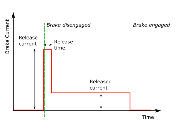
</AnalogBrake>There are 4 important values that will need to be tweaked to your hardware:
-
ReleaseCurrent: current required to release the brakes - the "Unit" field in the XML file is not read by the software, replacing it bymAwon't have any effect so make sure the specify theValuein amperes. -
ReleaseTime: amount of time you need to keep the current high to release the brakes (in seconds). -
ReleasedCurrent: current required to maintain the brakes released. This value should be significantly lower than the current to initially release the brakes. -
EngagedCurrent: current required to engage (lock) the brakes. On the ECM, always zero.
Please note that the values provided on this page are hardware specific and you must adjust them to your system. Ideally, you want to find the lowest possible current that still work reliably on your hardware, see below.
Current calibration needs to be performed for both the actuators and the brakes. Once you have generated the ECM XML configuration files, follow instructions from Calibration. The main difference for the ECM is that you need to follow the procedure twice, once without the -b option and once with the -b option. Overall, the process is:
-
sawRobotIO1394CurrentCalibration -c file.xmlfor the initial motor current calibration -
sawRobotIO1394CurrentCalibration -c file.xml-newto verify motor current calibration -
sawRobotIO1394CurrentCalibration -b -c file.xml-new-newfor the initial brake current calibration -
sawRobotIO1394CurrentCalibration -b -c file.xml-new-new-newto verify brake current calibration -
mv file.xml-new-new-new-new file.xmlto save the fully calibrated file
This is a VERY IMPORTANT PROCEDURE. At that point, we don't have a utility program the automatically adjust the parameters specific to the brakes, namely the 4 following values in the XML file:
-
ReleaseCurrentandReleaseTime ReleasedCurrent-
EngagedCurrent, though this one is easy, it should be set to 0.
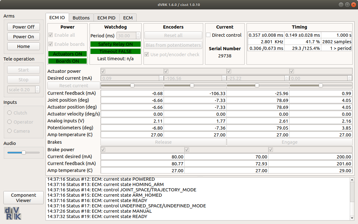
For this procedure we will use the sawRobotIO1394QtConsole program along with the ECM XML configuration file for your arm. You will need to manually edit the XML file and between changes, test using the sawRobotIO1394QtConsole program.
-
The first step is to determine the
ReleaseCurrent.- In the XML file, set all the
ReleasedCurrent(NOTE: releaseD current) to zero and theReleaseTimeto 10 seconds. Start from a low value for the 3ReleaseCurrentvalues (~0.1 for 100 mA). - Start the
sawRobotIO1394QtConsoleandEnable Allto power the actuators and brakes. - Press the
Releasebutton for the brakes. You should see the requested current move to the value set in the XML file and a current feedback close to it. After 10 seconds (or whateverReleaseTimeyou've set in the XML file), current should go back toReleasedCurrentvalue (i.e. 0 for now). - During these 10 seconds, try to move the ECM, joint by joint. If you stand close to the arm, you should even hear a click if the brakes get released.
- If a given brake is not released, quit the application, increase the value of
ReleaseCurrent(andMaximumCurrent) for the corresponding joint in the XML file and try again. - You can increase the requested current to an extent, i.e. the hardware is limited by the power supply so make sure you always check the current feedback. If the current feedback doesn't increase as you're increasing the requested current (and software maximum current), it means that you have reach the maximum possible with your power supply.
- In the XML file, set all the
-
Once you've found the proper values for
ReleaseCurrent, you can decrease theReleaseTimevalue to 2.0. -
The last step is to find the lowest possible for
ReleasedCurrent. This is the current appliedReleaseTimeseconds afterReleaseCurrentto keep the brakes from re-engaging. It's IMPORTANT to find the lowest possible value. Again, start from a low value and increase progressively until you find settings such that the brakes stay released.
We are not totally sure how much variability there is between systems. In order to get a sense for it, please update the following table after you calibrated your brakes:
| System | 1 Release (A) | 1 Release (s) | 1 Released (A) | 2 Release(A) | 2 Release (s) | 2 Released (A) | 3 Release(A) | 3 Release (s) | 3 Released (A) |
|---|---|---|---|---|---|---|---|---|---|
| JHU | 0.250 | 2.0 | 0.090 | 0.220 | 2.0 | 0.090 | 1.100 | 2.0 | 0.200 |
| ISI | 0.250 | 2.0 | 0.100 | 0.210 | 2.0 | 0.100 | 1.200 | 2.0 | 0.200 |
| WSU | 0.270 | 0.5 | 0.120 | 0.300 | 0.5 | 0.130 | 1.100 | 2.0 | 0.170 |
| UCL | 0.250 | 2.0 | 0.040 | 0.140 | 2.0 | 0.040 | 1.100 | 2.0 | 0.200 |
| PU | 0.250 | 2.0 | 0.130 | 0.180 | 2.0 | 0.100 | 1.100 | 2.0 | 0.200 |
Important note for older dVRK controllers: We found that the power requirements are close to the maximum amount of power a 24V power supply can deliver. There is some variability between different systems and brakes so you might need to upgrade the power supply to 36V in the controller enclosure. To check if you have reached the maximum deliverable power, keep an eye on the current feedback. These values should be close to the required current. If the current feedback seems to plateau while you increase the requested current, you'll likely need to upgrade your power supply.
Maximum values: Based on specification sheets that we believe correspond to the solenoid used for the 3rd brake (insertion) on the Classic and S/Si ECMs, we should not exceed 13W for 7 seconds or 1.3W for continuous drive. That would translate to 1.48A for the ReleaseCurrent and 0.465A for the ReleasedCurrent.
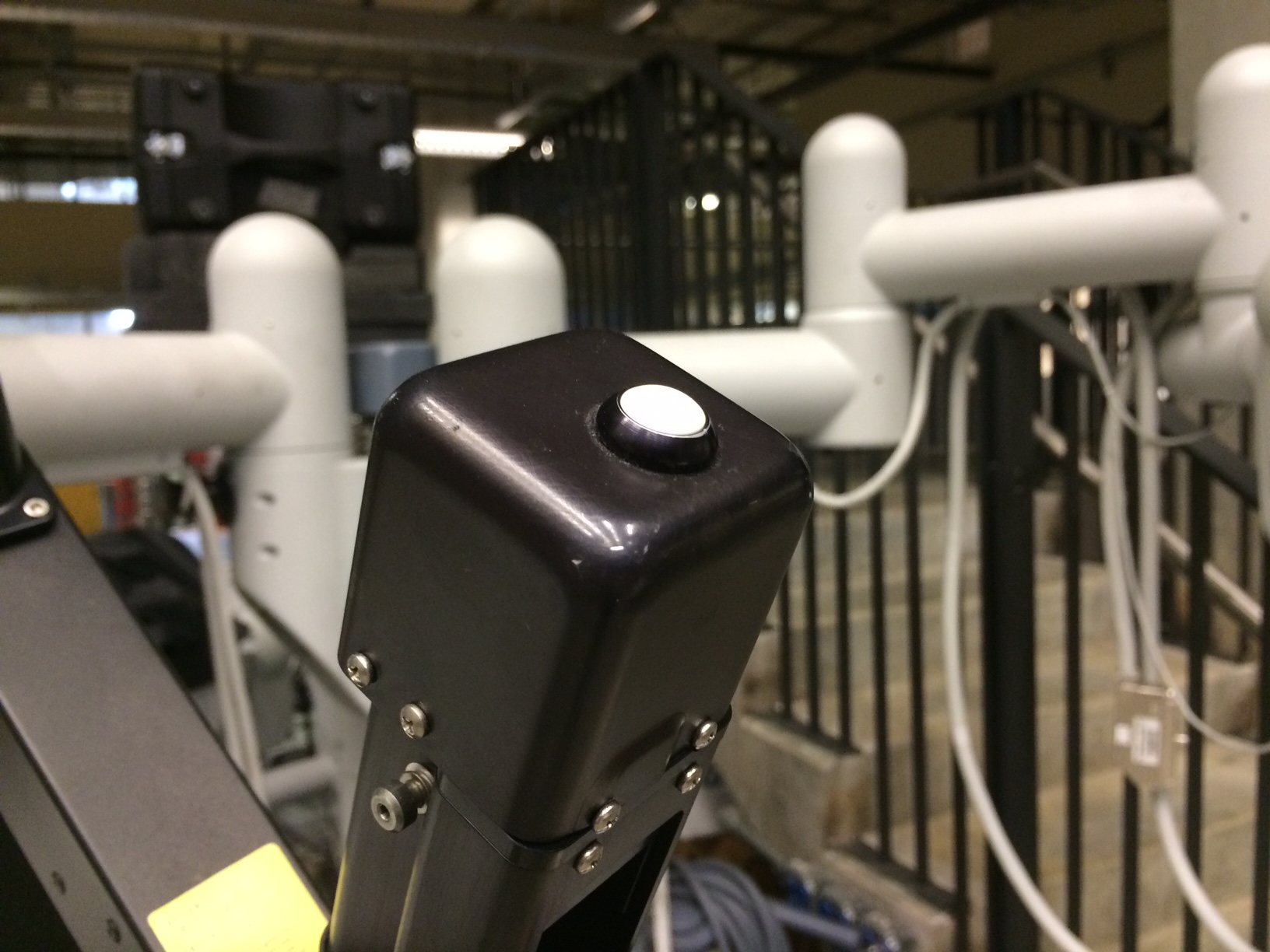
The setup joint switch/button on the ECM is not using the same digital input as the setup joint switch on the PSMs. This was unfortunately discovered after the dMIB were designed (pre 2015 revisions). In other words, you might have to modify the dMIB to short a couple pins. You will need someone in house who can do some soldering.
Using the sawRobotIO1394QtConsole you should be able to monitor the switch events, i.e. press and release the different buttons on the ECM arm for a little bit and monitor the changes in the "Buttons" widget/window.
-
Manipulator switch
-
SUJ switch

-
IO Widget
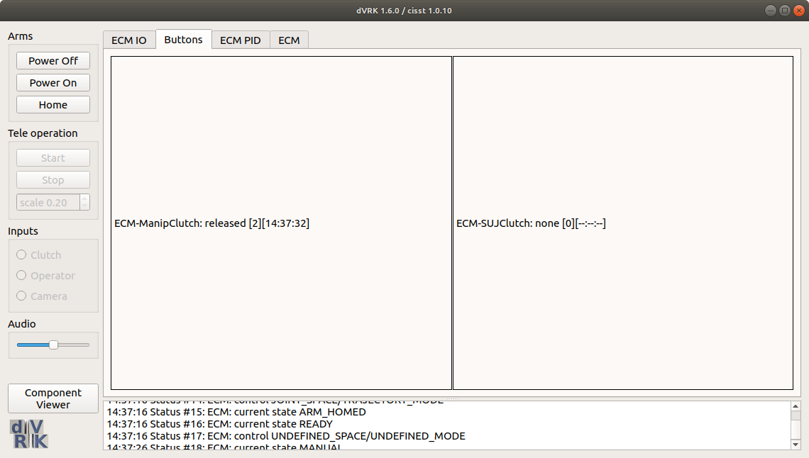
The Arm (aka manipulator) switch should work and the SUJ shouldn't until you hack the dMIB. To modify the dMIB, follow these instructions.
If you are absolutely sure the brakes are working (i.e. get released and stay released), you should be able to test the whole arm, including PIDs, homing, kinematics and manipulator clutch using the application sawIntuitiveResearchKitQtArm. The command lines syntax is:
sawIntuitiveResearchKitQtArm:
 -i <value>, --io <value> : configuration file for robot IO (see sawRobotIO1394) (required)
 -p <value>, --pid <value> : configuration file for PID controller (see sawControllers, mtsPID) (required)
 -k <value>, --kinematic <value> : configuration file for kinematic (see cisstRobot, robManipulator) (required)
 -n <value>, --arm-name <value> : arm name, i.e. PSM1, ... as found in sawRobotIO configuration file (required)
 -f <value>, --firewire <value> : firewire port number(s) (optional)
 -g <value>, --gcmip <value> : global component manager IP address (optional)
For the --arm-name or -n option, use the string ECM. For the -k option, use the file dvecm.rob. For the -p option, use the file sawControllersPID-ECM.xml. For the -i option, make sure you use the sawRobotIO XML file you generated for your system.
Once the application is started, hit the home button. The ECM should power properly, release the brakes and go to the zero position. You can then use the different widgets to make sure everything properly. You can press the manipulator clutch button to move the arm manually.

Community
Getting Started
- First Steps
- Software installation
- Controller Connectivity
- XML Configuration
- Hardware Setup
- Calibration
- Classic/Standard
- Si
- Examples
Advanced
- Software Architecture
- Application Development
- Config File formats
- APIs
- UI Customization
- Teleoperation
- Kinematics Simulation
- Potentiometer Issues
- Development Branches
- Release Checklist
- Projects
- Controllers/versions
- E-STOP Wiring
- Full da Vinci System
- Head Sensor
- Foot Pedals
- Video Pipeline
- Instruments
Miscellaneous
- Frequently Asked Questions
- User manuals Classic Si
- QLA Heat Sink
- Build w/o ROS Linux Mac
- cisst
- JHU
Deprecated