Hardware
Table of Contents generated with DocToc
Acronyms used in this document are defined in the FAQ.
Please read the unboxing instructions provided by ISI at http://research.intusurg.com/dvrkwiki/index.php?title=DVRK:Docs:Main
The arms need to be connected directly to the controllers. If you have a research kit (i.e. not the full patient cart) it is very easy. If you have a full patient cart, the controllers for the PSMs and ECM need to be connected to the cables that come from the arms. To do so, disconnect the arms (PSMs and ECM) from the back of the patient cart and plug them in the dVRK controllers. Do not use the long cables that connect the patient cart to the master console. See also the full daVinci page (Introduction section).
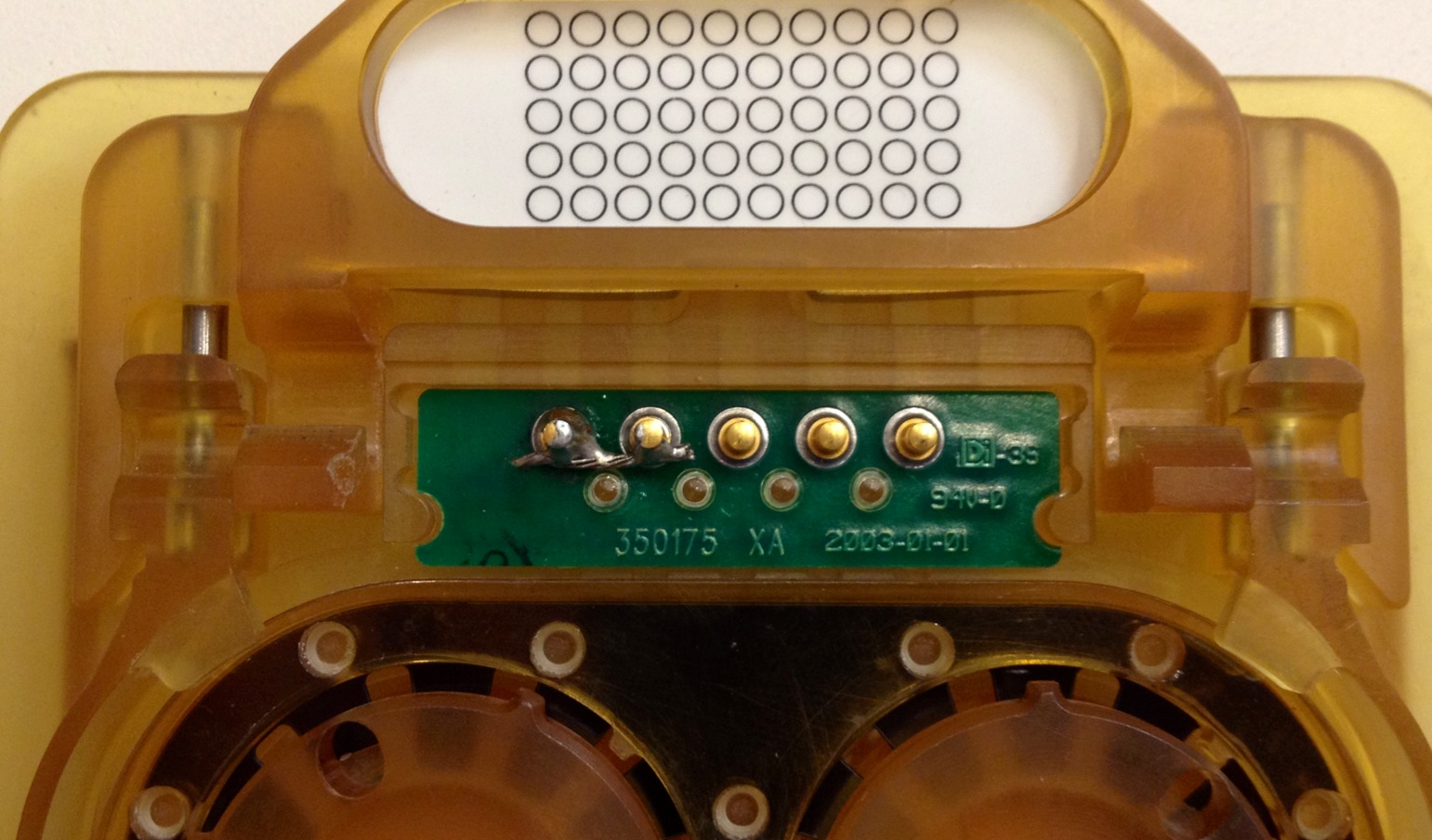
IMPORTANT: The PSMs have the ability to detect when a sterile adapter or tool is installed using digital inputs. For this to work, you will need to short a couple of pins on your sterile adapters (left two pins on the photo).
Make sure you place the wire to short the two pins as deep as possible and keep the extremities of the pins as clean as possible. If the tip of the pins are covered with soldering, you might have issues with the electric contact when inserting the adapter. This also affects the ability to read the instrument's Dallas chip (this applies to more recent systems, see Automatic Tool Detection). The dVRK controller should be able to reliably detect the sterile adapter. To check if the sterile adapter is properly detected, monitor the Buttons widget in the IO tab of the dVRK console GUI (see Widget examples).
-
There are three types of controllers, MTM, PSM and ECM. It is important not to mix them as the MTM controllers use a 24V power supply for the first 4 actuators and a 12V power supply for the last 3 actuators while the PSM controllers use a 24V power supply for all 7 actuators. For the ECM, there's a single 36V power supply for the 4 motors and 3 brakes. You can verify which one is which by opening the controllers. See also Controller Boxes.
-
We strongly recommend to label the controllers with the name of the arm you plan to control along with the board IDs. The board IDs should follow the convention described in the XML configuration page. Each controller contains two sets of boards. Each set is composed of a lower board (aka QLA for quad linear amps) and the upper board (FPGA + FireWire connections). The upper board (FPGA) has a rotary dial to set the board ID. Using a small screw driver you can change the Id for each board. For example, the controller dedicated to the MTM Right should have a label with:
MTMR (board IDs 2 - 3) -
When you will first unbox the controllers, check the internal connections. If you find a cable with a loose end or partially unplugged you'll have to plug it back. This is quite important, we've seen controllers that looked like they were delivered using a roller coaster!
-
We recommend plugging all your controllers to a single power strip with a switch. This will ensure that all controllers can be turned on or off using a single button.
Note: the following steps should be performed without connecting the arms to the controllers.
WARNING: The Firewire physical layer (PHY) chip on the FPGA board will be damaged if bus power (VP, typically 12V, but could be as high 40V) is accidentally applied to the differential data lines (TPA, TPA/, TPB, TPB/). We have seen this in two scenarios: (1) by physically forcing the Firewire cable upside down (difficult to do, but sometimes possible with strong hands and worn connectors), and (2) due to a failure in the PC Firewire card or a short in the cable. Please be careful, especially in the latter case, since connecting a shorted cable to each controller box will sequentially damage each FPGA board in the system!
This only applies to the first generation of controllers, i.e. 2012 model.
For the Rev 1 controllers, there is a minor issue with the controllers and power provided via the FireWire cable. If there are too many controllers on the daisy chain, there won't be enough power for the FPGA boards and they might get stuck in an unstable state. This is due to the fact that the Rev 1.1 FPGA boards (inside the Rev 1 controller box) can obtain power from the 6-pin FireWire cable or from its internal power supply -- specifically, the boards will use whichever voltage is higher. If the FireWire cable is connected to a box that is switched off, the FPGA boards will draw power from the PC via the FireWire cable. This problem does not occur with the Rev 2 controllers, which contain Rev 1.2 FPGA boards, because those boards have a jumper (J10) to enable/disable power from the 6-pin FireWire connector. By default, this jumper is not installed, so the FPGA boards cannot obtain power from the FireWire cable. The jumper was eliminated from the Rev 2.x FPGA boards, so it is not possible to encounter this problem with those boards.
-
For the Rev 1 controllers, if you are using a 6 pin FireWire A cable, we strongly recommend to unplug the FireWire cable from the PC, power on the controllers and then re-plug the FireWire cable on the PC. This way, the controllers start using their own power supplies.
-
If you are using a 4 pin FireWire A cable (this is often the case on PC laptops), you won't have any issue since these cables don't provide power over FireWire.
-
This is also not an issue with the Rev 2 and above controllers, unless you install jumper J10 on the FPGA boards.
Before you start any program, you need to make sure the controllers are properly identified on the FireWire bus. To do so, use the command line:
ls -al /dev/fw*
Note that the FireWire card in your PC shows as a FireWire node. So even if you have no FireWire device plugged on your PC, you should see fw0. You might have to unplug/replug the FireWire cable that comes from the controllers to your PC to force a FireWire bus reset. Wait 10 seconds before replugging. At that point, you should see some new fwX devices in /dev. If everything works as expected, you will see 2 new device handles per controller plugged on the FireWire chain (e.g. fw1, fw2...). The numbers must be continuous. If you see the device numbers skipping some values, it is likely because the kernel didn't have enough time to reset the handles. If this happens, force a bus reset by unplugging the FireWire cable from the PC, wait a bit longer and replug the FireWire cable.
Note: If you want to check what the Linux kernel is doing while plugging/unplugging the FireWire cable, open a separate shell and start dmsg -w.
To test the FireWire communication, the simplest solution is to use the command line tool qladisp. Assuming that you have built the software, qladisp can be found in the cisst build tree, subdirectory build/bin. The program requires one or more board IDs. The user can optionally specify a port number:
qladisp b1 [b2] [-pP]
For example, to display basic information related to the board with Id 3 on FireWire port 0, launch:
qladisp 3
You can monitor up to two boards. Here is a screen shot for qladisp using boards 0 and 1:

Verify that the FireWire cables you use are good, i.e. of good quality and not too long. We found that external cables longer that 4 meters often cause problems. To quickly check if your FireWire chain is healthy, start the qladisp utility and make sure:
- all boards are listed. You can verify the board IDs and firmware versions as well.
- the display doesn't freeze intermittently. The
dtvalue displayed on the first row is the maximum time in milliseconds between packets since the application started. The value should remain low (i.e. a few milliseconds). It will increase by about 80 milliseconds when you try powering the controllers. Values above 1 second usually indicate issues with the FireWire chain.
You should proceed methodically and add components one by one:
- Test with a single controller. Use a single FireWire cable between the PC and the controller and run
qladispfor each board in the controller (each controller box contains two boards). Test both FireWire port on the back of the controller. Test each controller individually. - Test with a second controller. Again, test each board on each controller connected.
- If you are running into issues (missing board or freezing display), try different cables.
NOTE: you can do this without enabling power in qladisp and E-Stop in off position but you will need the arms and foot pedal plugged.
NOTE: when you connect the arm to the controller, make sure you tighten the screw on the connector (1/4 turn) otherwise you might have a loose connection missing signals.
NOTE: the arguments passed to qladisp (e.g. 2 3) are board ID. The board ID is the rotary switch value (4-bit from 0 to F), which should be unique among daisy-chained controller boards. The board ID should be automatically set based on the following convention. Not all Research Kit come with the ECM and the PSM3 but the board Id should be reserved nevertheless:
| MTML | MTMR | ECM | PSM1 | PSM2 | PSM3 | |
|---|---|---|---|---|---|---|
| Board ID 1 | 0 | 2 | 4 | 6 | 8 | 10 (A) |
| Board ID 2 | 1 | 3 | 5 | 7 | 9 | 11 (B) |
The simplest way to test these inputs is to use qladisp and make sure all digital inputs are wired. qladisp has been designed for generic applications where digital inputs can be used for limit and home switches. Since the da Vinci doesn't have limit and switch limits the digital inputs are used for buttons and pedals. In the qladisp, you still need to look for NegLim, PosLim and Home. Since qladisp allows to display up to two boards, we'll refer to NegLim1, NegLim2, ...
On the master side, all inputs are related to the foot pedal so only one of the controllers will display any information: using if the foot pedal is connected to MTMR controller:
qladisp 2 3
If the foot pedal is connected to MTML controller:
qladisp 0 1
You should have the following default values (no pedal pressed)
NegLim1: 0xF PosLim1: 0xF Home1: 0xF NegLim2: 0x7 PosLim2: 0xF Home2: 0xF
Pressing foot pedal:
- Clutch -> Home2: 0xE
- Camera -> PosLim2: 0xE
- Cam+ -> Home2: 0xB
- Cam- -> Home2: 0xD
- Coag -> Home2: 0x7 (note COAG is sometimes labeled "Mono", first pedal on the right)
For the PSM:
qladisp 6 7
You should have the following default values (no button pressed, no sterile adapter, no tool, ...)
NegLim1: 0xF PosLim1: 0xF Home1: 0xD NegLim2: 0x7 PosLim2: 0xF Home2: 0xF
Pressing buttons and inserting sterile adapter or tool:
- SUJ clutch button (white button horizontal bar on the side) -> Home1: 0xE
- Tool clutch button (white button on top) -> Home1: 0x9
- Sterile adapter (modified) -> NegLim2: 0x3
- Tool -> PosLim2: 0x7 (tool adapter should still be in so NegLim2 should still be 0x3)
NOTE: you should perform these tests with the arms unplugged.
NOTE To test individual board, you need to bypass relay, FOLLOW instruction on the ESTOP page.
Motor power can be disabled by hardware interlocks (relays, e-stop) or by software, so it is necessary to first inspect the hardware setup. Specifically, the e-stop cable harness is usually designed to daisy-chain the safety circuit between multiple controllers. Thus, if you wish to individually test controllers, you may need to temporarily modify your e-stop cable harness. See this page for further instructions.
Once the e-stop cable harness is suitably modified, the simplest solution is to use the QLA utility qladisp (Mechatronics Examples) for each board on your hardware and try to enable/disable power (press p key) with and without your wired E-stop engaged.
- When the power is ON you should have:
-
MVLED should be green (MV stands for motor voltage) -
Fault xLEDs should turn red (4 at a time)
Once you have checked the overall hardware, you can calibrate and update XML configuration files. To test the configuration files, please use the example sawRobotIO1394QtConsole as described in the examples page.

Community
Getting Started
- First Steps
- Software installation
- Controller Connectivity
- Configuration files
- Hardware Setup
- Calibration
- Classic/Standard
- Si
- Examples
Advanced
- Software Architecture
- Application Development
- APIs
- UI Customization
- Teleoperation
- Kinematics Simulation
- Potentiometer Issues
- Development Branches
- Release Checklist
- Projects
- Controllers/versions
- E-STOP Wiring
- Full da Vinci System
- Head Sensor
- Foot Pedals
- Video
- Instruments
Miscellaneous
- Frequently Asked Questions
- User manuals Classic and Si moved
- QLA Heat Sink
- Build w/o ROS Linux Mac
- cisst
- JHU
Deprecated