SUJ
- Introduction
- Labels
- Mounting and connecting the dVRK SUJ controller
- dVRK configuration files
- Calibration
- Simulation
Acronyms used in this page are defined in Frequently Asked Questions.
This page describes how to use the Classic (aka Standard) Setup Joints (SUJs) with the dVRK. This is useful only for the groups with a full da Vinci.
The SUJs (Set Up Joints) are passive arms with electric brakes. They are used to position the patient side arms remote centers of motion (RCM) on the patient. Once the system is set up for a surgery, the SUJs are not supposed to be moved until the end of the surgery. Depending on the daVinci, there are between 3 and 4 SUJs mounted on the patient cart. All systems have an ECM SUJ mounted on the front of the support column. All systems also have 2 PSM SUJs, one for the PSM1 (mounted on the right) and one for the PSM2 (mounted on the left). For systems with a third PSM, the PSM3 SUJ is mounted on the front of the center column, under the ECM SUJ.
The setup joints use potentiometers to read the joint positions. Each joint has two potentiometers and each arm has up to 6 joints. So we have a total of 48 potentiometers, each provides a voltage that needs to be converted to an angle (revolute joints) or distance (prismatic joints).
The brakes are controlled per arm, not per joint. The SUJ arms for the PSM1, PSM2 and ECM have counter weights inside the vertical column so they can be moved up and down manually once the brakes are released. Finally, some patient carts come with a third PSM (aka PSM3). The PSM3 SUJ is mounted under the ECM SUJ and doesn't have a counter weight for up and down motion. It can be lifted using a separate motor mounted at the base of the patient cart.
See dVRK controllers page for hardware description.
The dVRK software stack provides all the functions and parameters needed to compute the forward kinematic of the SUJ arms based on the joint values. Furthermore, it maintains the transformation tree between all the kinematic chains so that the PSM tip will be defined wrt the ECM tip (including active ECM motion).
Important note: The SUJ arms are not very accurate. The overall accuracy of the PSM tip wrt the ECM tip should be within +/- 5 cm (centimeters) and a few degrees. They are designed to provide an estimated base frame for a tele operation task with a human in the loop. In that case, relative translations don't matter and relative orientation has to be a reasonable estimate (5 to 10 degrees error doesn't affect performance significantly). If you need a more precise estimation for the PSM position wrt the ECM, you will need to implement your own registration method.
Physical buttons are also used by the software to release the SUJ brakes and the SUJ PSM3 lift. The following "buttons" are supported:
- Physical button on SUJ arms (black handle). The only SUJ arms with this button are the SUJ PSM1 and SUJ PSM2.
- Physical button on the actual arm (i.e. ECM or PSM). On the ECM, black handle on top of parallel link. On the PSMs, white button on the side of the parallel link. Note: the software can only handle these buttons if the actual arm controller (i.e. ECM, PSM1, PSM2 and/or PSM3) is used by the dVRK software since these buttons are wired along the other arm signals.
- Software "clutch" button for all SUJ. The "button" is found in the Qt widget for the SUJ arm. You have to press continuously on the button to release the brake. This logic prevents users from accidentally keeping the brakes released.
- Physical lift toggle button on PSM3. This button is usually attached on the parallel link of the PSM3 using a velcro strap.
- Software "lift" up and down buttons for SUJ PSM3.
All dVRK arm can be used in simulation mode, this includes the SUJs. There are two main applications for the simulation mode with the SUJs:
- Simulate the whole patient cart. At that point all PSMs and the ECM are also simulated.
- Simulate only the SUJs. This can be used if you don't have access to the dVRK SUJ controller. With the simulation mode, you have to find the SUJs joint values (e.g. using labels) and then set the joint values using ROS. Once this is done, the software can compute the SUJs forward kinematic and provide all the base frames you need for the PSM and ECM teleoperation. See details in the Simulation section.
To use the SUJs with the dVRK controller and/or the dVRK software, the main challenge is to determine the current position of each joint. This has to be done if you have the dVRK controllers (for calibration) or if you plan to use the SUJs in simulation mode. To help with this task, we provide some custom labels that can be attached to each joint of the SUJs.
These dimensions are used to determine the scales on the labels.
Joints diameters:
- 0: Translation, where's the origin?
- 1: Rotation, vertical axis, diameter 147.5 mm, circumference 463.4 mm (all -90/+90)
- 2: Rotation, vertical axis, diameter 133.5 mm, circumference 419.4 mm (PSM1 -135/0, PSM2 0/+135, PSM3/ECM -90/+90)
- 3: Rotation, vertical axis, diameter 107.5 mm, circumference 337.7 mm (all -90/+90)
- 4: Rotation, horizontal axis, diameter 93.3 mm, circumference 293.1 mm (PSMs only -135/+135)
- 5: Rotation, "vertical" axis, diameter 89.4 mm, circumference 280.9 mm (PSMs only -135/+135)
You can download a document to print on letter paper: dVRK labels for SUJ. The .svg file can be opened, modified and printed using inkscape on Linux. You can also find a pdf version if you don't have inkscape. Please, if you update the .svg file, make sure you also update the .pdf and send the updated version to JHU.
We used clear polyester labels (Hemmi Papilio Supplies, Gloss White/Clear Polyester, 3 mil with permanent adhesive, SKU: HPGC/HPGW) but you can also use plain white paper with double sided tape on the back.
Every joint moves in the positive direction when turned counter clockwise and in the negative direction when turned clockwise. This is why the labels for joint 4 on the three PSMs are the only labels with negative values on the left and negative values on the right.
The label for joint 3 of the ECM is made so that 180 is the value that is aligned with the divot in the joint because the 0 position for the ECM is where the ECM is facing the support column.
Make sure to put the labels on the link before the joint.
PSM1 and PSM2 have identical SUJs except for their second joints that have the same geometry but have different bounds of rotation (PSM1 moves from -135 to 0 and PSM 2 moves from 0 to 135). This is why the directions for their label placement is the same.
| ECM | PSM1 | PSM2 | PSM3 |
|---|---|---|---|
| ECM Labels PDF | PSM1 Labels PDF | PSM2 Labels PDF | PSM3 Labels PDF |
| ECM Labels SVG | PSM1 Labels SVG | PSM2 Labels SVG | PSM3 Labels SVG |
After printing the labels, make sure your computer or printer didn't scale the document to fit the paper. There is a printed reference on the labels that should measure 20 cm.


For the ECM, make sure the label for the 3rd joint is positioned so 180 is on the divot.


The simplest way to create the configuration files for your system is to start from the files in the share/jhu-daVinci directory. The main files are:
-
sawRobotIO1394-SUJ.xml. This file is unique to each systems since it is calibrated for current feedback (see current calibration) so you should keep it in your system's directory (e.g.share/mylarb-daVinci). -
suj-ECM-1-2-3.json. This file contains the DH parameters for all the SUJs as well as the calibration results for the potentiometers to joint values conversion. As such, this file is also specific to each system. -
console-SUJ*.json. These files are used with the dVRK console application (i.e.sawIntuitiveResearchKitQtConsoleJSONorrosrun dvrk_robot dvrk_console_json). If you're creating a configuration file with the SUJs and the actual arms (ECM and PSMs), don't forget to set thebase-framefor each active arm (see example inshare/jhu-daVinci).
When you're using the dVRK SUJ controller, the joint values are measured using potentiometers. The voltage measured has to be converted to an angle using a simple linear transformation. Since each system has different potentiometers, each system need to be individually calibrated. To do so, the dVRK GUI provides a very simple interface that allows to compute the scale and offset for the linear transformation using two set points. At each point, the controller will provide the voltage and the user has to provide the measured angle using some kind of external measurement tool.
For all the rotational joints, we found that the labels provide a reasonable estimate. For the translation joints, we don't currently have a good system. The process described here relies on a cheap laser measurement tool.
![]()
The main steps to perform the calibration for one SUJ are:
- Position the joints one by one (it's easier if you're in a small space)
- Release the brakes (you might need a helper to press the GUI "Clutch" button in the arm SUJ tab)
- Position the arm to one extreme of the joint space, at a position with a reading on the labels you attached to the joint
- Re-engage the brakes
- Wait a few seconds for the position to be measured by the dVRK controller (we rely on potentiometers and a multiplexer so it takes time to cycle through all 24 potentiometers)
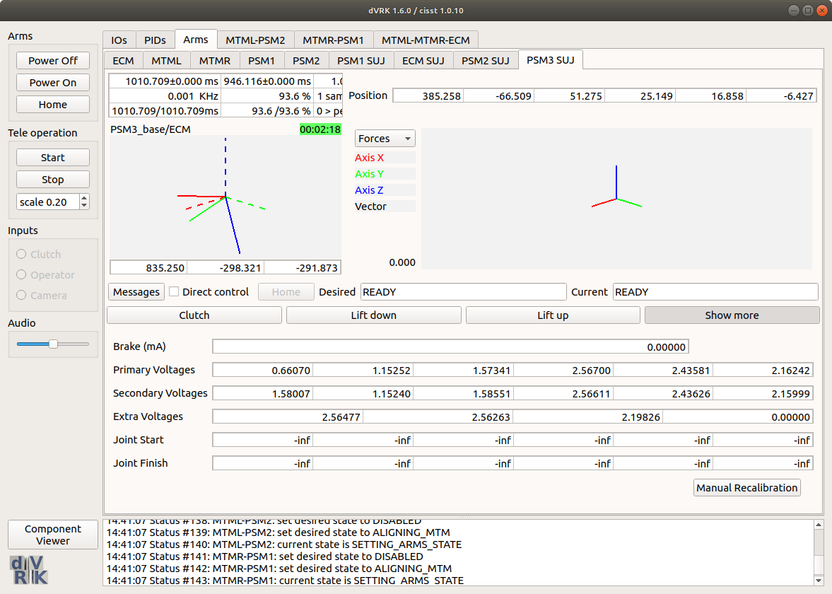
- Enter the joint position you read on the label in the GUI "Joint Start" (click on the "Show more" button to see the calibration widget). By default the position is set to
-inf. When you enter the actual joint position, the application records the current potentiometer value - On the same joint, go to the other extreme position and enter the real joint position in "Joint Finish". The point of using 2 positions as far as possible to each other is to minimize the error when we're computing the slope for the potentiometer to position linear function. "Joint Start" and "Joint Finish" can be in any order, i.e. that start joint value doesn't have to be smaller than the joint finish value.
- Repeat for all 6 joints on your SUJ. If you're calibrating the ECM SUJ, enter bogus values for the last two joints. Just make sure these values are all different.
- Once you've entered all the joint positions needed (i.e. 4x2 for ECM SUJ, 6x2 for PSM SUJs), hit the "Manual Recalibration" button.
- The manual recalibration is a simple line fit for each pair of positions. The result will be printed in your terminal, you have to manually copy/paste the new values to your SUJ configuration file (e.g.
suj-ECM-1-2-3.json). The output should look like:When you copy/paste these values to your configuration file, make sure you're modifying the section for the SUJ you're currently calibrating.SUJ scales and offsets for arm: Timestamp (auto): 0.14189 (valid) Value: PSM3 Please update your suj.json file using these values "primary-offsets": [ 2329.7, -59930, 1.9507e+05, -2.6861e+05, -2.3586e+05, -3.0817e+05], "primary-scales": [ -5461.2, 98040, -57190, 98040, 1.0558e+05, 1.3726e+05], "secondary-offsets": [ -23431, 28095, -2.0391e+05, 1.8798e+05, 1.9171e+05, 2.1985e+05], "secondary-scales": [ 17476, -45752, 59677, -68628, -85785, -98040], - When you're done calibrating all SUJs, quit the dVRK console application and restart it to test the calibration
The dVRK graphical table has two rows and six columns. The first column is for joint 0, second for joint 1, third for joint 2, and so on.
To calibrate joint 0 it is necessary to have a laser measuring tool. The procedure for calibration is as follows:
- Lower the PSM to its lowest point.
- Place the measuring tool underneath joint 1 as shown in the picture below.
- Find and record the height of the PSM.
- Enter 0 in the graphical table in the first column of the first row.
- Raise the PSM to its highest point.
- Find and record the height of the PSM.
- Subtract the final height from the initial height.
- Enter the difference in height in the second column of the first row.
The procedure for calibration is as follows:
- Turn the joint to an extreme (either its highest or lowest degree measurement on the label).
- Enter that angle into the graphical table in the first row and in the column that corresponds with the joint.
- Turn the joint to the other extreme.
- Enter that angle into the graphical table in the second row and in the column that corresponds with the joint.
- Repeat until all 5 joints have values in the top and bottom row.
To calibrate joint 0 it is necessary to have a laser measuring tool. The procedure for calibration is as follows:
- Lower the PSM to its lowest point.
- Place the measuring tool underneath joint 1 as shown in the picture below of PSM1 (all 3 PSMs have similar flat pieces under their joints).
- Find and record the height of the PSM.
- Enter 0 in the graphical table in the first column of the first row.
- Raise the PSM to its highest point.
- Find and record the height of the PSM.
- Subtract the final height from the initial height.
- Enter the difference in height in the second column of the first row.
- Anton, we need to add something here about adjusting the offset.
The procedure for calibration is as follows:
- Turn the joint to an extreme (either its highest or lowest degree measurement on the label).
- Enter that angle into the graphical table in the first row and in the column that corresponds with the joint.
- Turn the joint to the other extreme.
- Enter that angle into the graphical table in the second row and in the column that corresponds with the joint.
- Repeat until all 5 joints have values in the top and bottom row.
The ECM can only be calibrated after calibrating PSM1 or PSM2
The procedure for calibration is as follows:
- Lower the ECM to its lowest point.
- Lower PSM1 to the point at which the bottom of PSM1's second joint and the ECM's second joint are level as seen below.
- Record the reported height for PSM1 from the graphical as the initial height of the ECM.
- Enter 0 in the graphical table in the first column of the first row.
- Raise the ECM to its highest point.
- Raise PSM1 to the point at which the bottom of PSM1's second joint and the ECM's second joint are level as seen below.
- Subtract the final height from the initial height.
- Enter the difference in height in the second column of the first row.
The procedure for calibration is as follows:
- Turn the joint to an extreme (either its highest or lowest degree measurement on the label).
- Enter that angle into the graphical table in the first row and in the column that corresponds with the joint.
- Turn the joint to the other extreme.
- Enter that angle into the graphical table in the second row and in the column that corresponds with the joint.
- Repeat until all 3 joints have values in the top and bottom row.
- Fill the last two columns in with random numbers as place holders.
When the table is full of values hit "Manual Calibration" and the correct offsets and scales will print in the terminal.
When the calibration is complete, place all the RCMs together and check that their reported values on the graphical are within a 20 mm cube of each other. (This is show in the pictures labeled PSM3)
![]()
![]()


![]()
![]()
To configure the SUJs in simulation mode, you will need to add the following in your console configuration file:
    "arms":
    [
        {
            "name": "SUJ",
            "type": "SUJ",
            "simulation": "KINEMATIC",
            "kinematic": "arm/suj-simulated.json",
            "base-frame": {
                "component": "ECM",
                "interface": "Robot"
            }
        }
For the rest of your console configuration and more specifically settings for the base-frame, see the console-SUJ-*.json files in share/jhu-daVinci directory and the file console-patient-side-simulated.json in share/console.
In simulation mode, when you start the dVRK software, all the SUJs joint values are set to zero. You have to send the proper joint values using ROS topics. Note that all values should be using SI units (meters for the first joint and radians for all remaining joitns) and all arms expect 6 values (the ECM only need 4 so set the 5th and 6th values to 0.0). The ROS topics to use are:
/SUJ/ECM/move_jp/SUJ/PSM1/move_jp/SUJ/PSM2/move_jp/SUJ/PSM3/move_jp
You can send your joint values from the command line using the rostopic pub command. For example:
rostopic pub /SUJ/PSM2/move_jp sensor_msgs/JointState "header:
  seq: 0
  stamp: {secs: 0, nsecs: 0}
  frame_id: ''
name: ['']
position: [0.0735, 0.249, 1.438, 0.283, 0.379, 0.606]
velocity: [0]
effort: [0]"
When using the ROS command line, make sure you take advantage of auto-completion (press "tab" key repeatedly). This will automatically fill the message type as well as an empty message. Then you can just copy/paste your position vector.
If you want to use the SUJs simulation mode to emulate the dVRK controller with a real patient's cart, you will need to use the clinical mode (i.e. original da Vinci controller) to release the brakes and optionally lift the PSM3. If you are lucky and have access to the ISI Research API in the clinical mode, you might be able to get the actual joint values for your SUJs, write them down and then send them to the dVRK SUJ in simulated mode.
Note: If you are using the SUJ just to find the relative orientation of the PSM coordinates systems with respect to the ECM coordinate system so you can tele-operate the ECM and PSM with the dVRK stack, translations don't matter! That means that you don't need to pay attention to the translation stage (joint 0) on the SUJs. This will make your life a bit easier since we don't have labels for the translation stage.

Community
Getting Started
- First Steps
- Software installation
- Controller Connectivity
- Configuration files
- Hardware Setup
- Calibration
- Classic/Standard
- Si
- Examples
Advanced
- Software Architecture
- Application Development
- APIs
- UI Customization
- Teleoperation
- Kinematics Simulation
- Potentiometer Issues
- Development Branches
- Release Checklist
- Projects
- Controllers/versions
- E-STOP Wiring
- Full da Vinci System
- Head Sensor
- Foot Pedals
- Video
- Instruments
Miscellaneous
- Frequently Asked Questions
- User manuals Classic and Si moved
- QLA Heat Sink
- Build w/o ROS Linux Mac
- cisst
- JHU
Deprecated