ESTOP archive
Table of Contents generated with DocToc
We mplemented a module e-stop connection at JHU using mini-DIN connectors. The female connectors are Digikey P/N CP-2140-ND (free hanging) or CP-2540-ND (panel mount). The male connector is Digikey P/N CP-2040-ND (free hanging). For the extension cable, it is possible to use an S-Video cable IF the pin carrying the 12V is cut (pin 1 in the drawing below). Otherwise, you would also connect the 12V supplies together, as in the Parallel Connection below, though at least the current would not flow through the safety relays.

Implementation Guide
This guide documents the steps to implement this configurable serial connection using S-Video (Mini-DIN-4) connector and S-Video cables.
List of Materials: (To make E-STOP wiring for N boxes)
- 1 E-STOP
- 2 male connector (Digikey P/N CP-2040-ND)
- 1 for E-STOP
- 1 for termination plug
- 2 x N female connectors (Digikey P/N CP-2140-ND)
- N-1 S-Video cables
- (2 + 2 x N) x 4 Molex pin connectors (Digikey Part No. WM2510-ND)
Example: a 4-box system:
- 1 E-STOP
- 2 male connector (Digikey P/N CP-2040-ND)
- 8 female connectors (Digikey P/N CP-2140-ND)
- 3 S-Video cables
- 40 Molex pin connectors (Digikey Part No. WM2510-ND) NOTE: we do recommend you order 2 more male and 2 more female connectors in case you broke one and their unit price is around $1.50 in small quantity.
WARNING: the pinout for male and female connectors are different!
- Step 1: E-STOP. Solder the two pins of E-STOP to pin 1 and pin 2 of a male connector, respectively.
- Step 2: Termination Plug. Short pin 2 and pin 3 of a male connector.
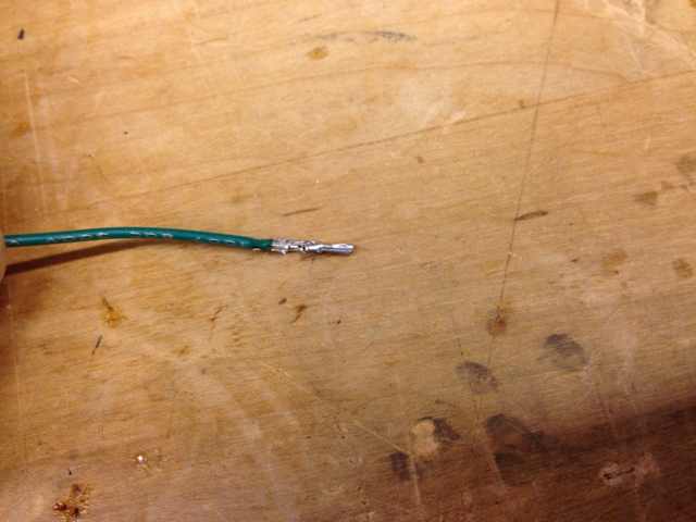
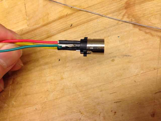
- Step 3: Female Connector. Solder pins according to the schematic. Wire colors:
- Pin 1 - RED 12 V
- Pin 2 - YELLOW S
- Pin 3 - GREEN EN
- Pin 4 - BLACK GND


- Step 4: S-Video Cable. Modification on the S-Video cable is required to prevent connecting 12 V power supply. Bend pin 1 at both ends of the S-Video cable, as shown in the following figure.

Reference: S-Video Pinout:

Male connector

Female connector
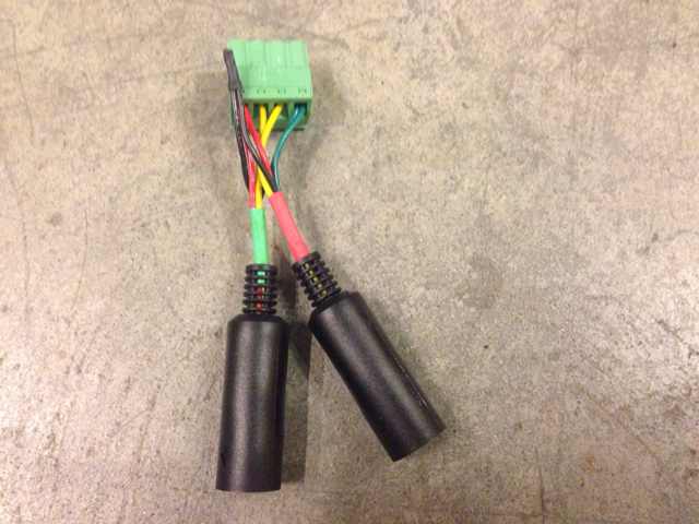
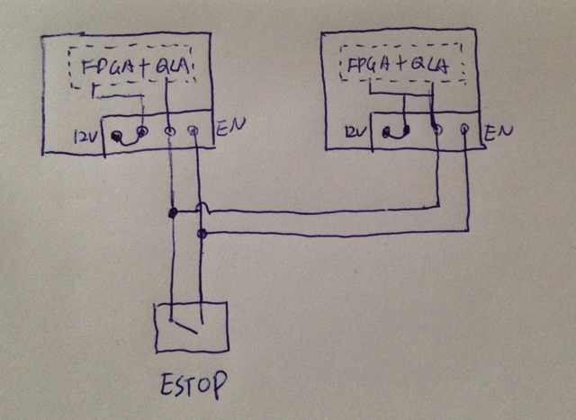
The advantage is that the connection is parallel, so it can be used for any number of controller boxes. For example, the figure below shows an e-stop cable connected to two controller boxes. But, you can also use it to control just one controller box (i.e., it still works if the second connector is not used). But, there is a major drawback to this wiring strategy. The drawback is that the 12V power supplies in the boxes will all be connected together when the QLA safety relays are closed. It is generally not a good practice to connect power supplies, since the power supply with the highest output voltage will source all the current, until the high load current causes its output voltage to drop below the output of one of the other power supplies (note that the load current will be high because the 12V supply also provides the logic power for the FPGA boards). Even worse, the current that flows from one box to the others all flows through the contacts of the QLA safety relay. If this current is too high, it will permanently weld the relay contacts, destroying the relay (which is not easy to replace). This has actually happened at JHU, destroying the relays on 9 QLA boards. At JHU, the problem was exacerbated by the fact that one of the "12V" power supplies in the controller box was actually a 24V supply, so when the safety relays were closed, this power supply provided current to all controllers (thereby powering all FPGAs). But, this problem could potentially happen in systems that only have 12V supplies, since their output voltages will not be exactly equal. It is easy to test whether the relay contacts have been fused by checking continuity (it should be normally-open, so if there is continuity when the system is powered off, it has been fused).

Community
Getting Started
- First Steps
- Software installation
- Controller Connectivity
- XML Configuration
- Hardware Setup
- Calibration
- Classic/Standard
- Si
- Examples
Advanced
- Software Architecture
- Application Development
- Config File formats
- APIs
- UI Customization
- Teleoperation
- Kinematics Simulation
- Potentiometer Issues
- Development Branches
- Release Checklist
- Projects
- Controllers/versions
- E-STOP Wiring
- Full da Vinci System
- Head Sensor
- Foot Pedals
- Video Pipeline
- Instruments
Miscellaneous
- Frequently Asked Questions
- User manuals Classic Si
- QLA Heat Sink
- Build w/o ROS Linux Mac
- cisst
- JHU
Deprecated