Debugging Potentiometer Issues
Table of Contents generated with DocToc
The dVRK uses the analog potentiometers on the robotic arms to:
- Home the arms. The encoders are relative encoders so we use the potentiometers to find and pre-load the zero value. See potentiometer calibration.
- Perform safety checks. Once the arms are powered, the dVRK software continuously monitors the joint (or actuator based on each type of arm) positions reported by both the encoders and the potentiometers.
For the safety checks, we use two different parameters per potentiometer. Consistency is based on:
- Distance, i.e. error tolerated in position between both (
|pots - encoders|) readings - Latency, i.e. amount of time during which the distance is continuously above a given threshold
The challenge is to find the "best" distance and latency for each system.
Important notes regarding the MTMs
- The last motorized joint (7), i.e. the roll has a potentiometer but the dVRK doesn't use it, neither for homing nor for safety checks. To avoid errors we simply set a very high Distance threshold. In Rev 1.6 and above, the value 0.0 should be used to simply disable the safety check. Please ignore the reported analog position for this axis.
- The very last "joint" (8), i.e. the gripper doesn't have an encoder. The dVRK only uses the analog input of the 8th axis (no encoder, no motor). The analog input is the value from the Hall effect sensor in the MTM gripper. As for the 7th axis, we set a very high Distance threshold to avoid errors. In Rev 1.6 and above, the value 0.0 should be used to simply disable the safety check. Please ignore the reported encoder joint and actuator positions as well as velocities.
If you're running into error messages regarding potentiometer and encoder inconsistencies, the first thing to check is the physical connections. Potentiometers feedback is an analog signal and is sensitive to bad connections/grounding. Check:
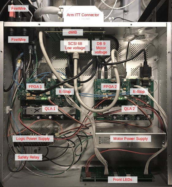
- The large Cannon ITT connector at the back of the dVRK controller (see Cannon ITT. Make sure the connector is clean and the screw on the back is tighten (a quarter turn).
- The two Micro DB68 SCSI cables between the dMIB and the QLA boards (see FAQ for acronym definitions).
For each connection (i.e. ITT connector and both ends of the DB68 cable):
- Clean the connectors, we recommend both compressed air (canned) and contact cleaner (e.g. WD Contact Cleaner). You should clean both the cable ends and the connectors on the PCBs
- Make sure all screws are tight
It is possible that one of the encoders or the potentiometers is defective. The easiest way to check this is to use the graphical user interface and control the robot using the IO widget.
Start the console application and configure the system without homing:
- Do not hit Power On nor Home buttons. If you have, just hit Power Off
- Select the IO tab corresponding to your arm
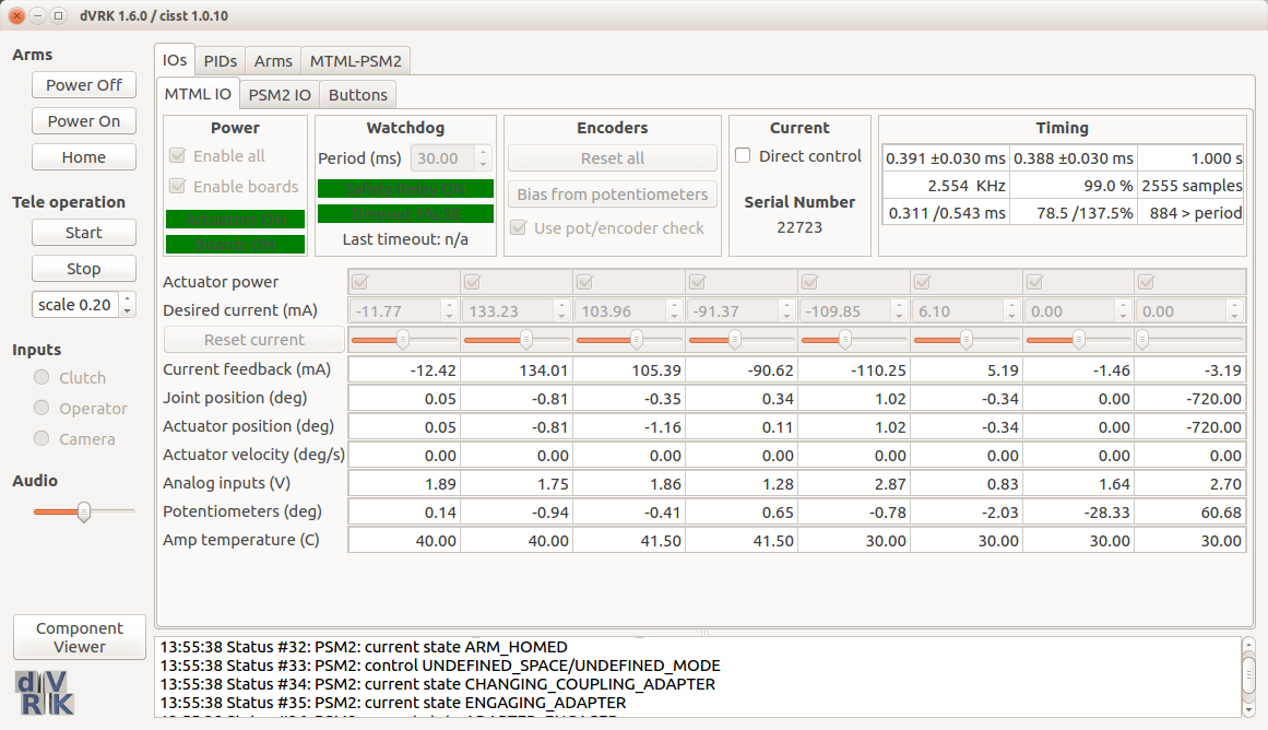
- In the IO tab, check Direct control and approve
- If you just started the console application and the arm hasn't been moved, both Joint position and Actuator position rows should be close to zero
- The Potentiometer values will be oscillating but should be fairly stable (e.g. a few tenths of degrees/millimeters)
- Then click Bias from potentiometers. This step will pre-load the encoders based on the potentiometers
- The box Use pot/encoder check should be unchecked.
At that point, you will need to move the arm by hand. If you're using a PSM or ECM, remove any tool, sterile adapter or endoscope to make it easier to back drive the arm.
Import note: If you're using an ECM, make sure you have someone helping you who can Release and Engage the brakes using the graphical user interface. Someone must be holding the ECM when the brakes are released so it won't fall down.
For each joint:
- Move the joint to a physical limit (e.g. lower limit)
- Check in the GUI that the Potentiometer value is close to the *Joint (MTM) or Actuator value (PSM and ECM). Write down that value.
- Move the joint to the other physical limit (e.g. upper limit) and check values (see step 2).
- Go back to first physical limit (e.g. lower limit) and make sure you get a reading close to what you got on step 1.
If the values are not consistent within a few degrees/millimeters (these are the units used for the dVRK GUI), you likely have a broken encoder or potentiometers.
If you're using a recent dVRK version (2.1+), there is now an option to plot the encoder and potentiometer values directly in the console application. In the IO tab, under "Service", check "Plot position". You can then select which joint/actuator to display using the drop down menu on the left. This can be used to get a sense of what the issue is (scale, latency...). The output is not as detailed as what you can get with ROS bags and PlotJuggler (see section below) but it's a lot faster.
We found that some potentiometers can be "somewhat" working so it is possible to tweak (increase) the parameters used to trigger an error by modifying the IO configuration file. Locate the file sawRobotIO1394-xxx-11111.xml for your arm and open it using your preferred text editor. In that file, find the Potentiometers section:
   <Potentiometers Position="Joints">
      <Tolerance Axis="0" Distance="5.00" Latency="0.01" Unit="deg"/>
      <Tolerance Axis="1" Distance="5.00" Latency="0.01" Unit="deg"/>
      <Tolerance Axis="2" Distance="5.00" Latency="0.01" Unit="deg"/>
      <Tolerance Axis="3" Distance="5.00" Latency="0.01" Unit="deg"/>
      <Tolerance Axis="4" Distance="5.00" Latency="0.01" Unit="deg"/>
      <Tolerance Axis="5" Distance="5.00" Latency="0.01" Unit="deg"/>
      <Tolerance Axis="6" Distance="1000.00" Latency="0.01" Unit="deg"/>
      <Tolerance Axis="7" Distance="1000.00" Latency="0.01" Unit="deg"/>
   </Potentiometers>
The first parameter to increase should be the Latency. The value is given in seconds. Try to increase it progressively by doubling it and restart the console (no need to power on/off the controllers). If the system is still not stable, double the Latency and try again. If the system is still not stable with a Latency of 1 seconds (1.0), try the same approach with the Distance parameter.
Note: In Rev 1.6 and above, instead of using a high Distance value to disable the safety check on a given joint, simply set the Distance to zero (i.e. 0.0).
The goal of this section is to show how to collect both the encoder and potentiometer values for a given arm and plot the results. You can also bypass the data collection with rosbag and visualize the data live.
To collect the data or view the data live, you will need to start the console with an extra option to turn on publishing of some low level data. For a PSM, you would have to start the console using the extra -i option:
rosrun dvrk_robot dvrk_console_json -j jhu-daVinci/console-PSM3.json -i ros-io-PSM3.jsonNotes:
- Use your own console.json file (see console file format)
- The configuration files
ros-io-XYZ.jsonare distributed along the dVRK code in thesharefolder (you can navigate to the configuration folder usingroscd dvrk_config)
Once the console is started with the ROS IO option, you should see the following two new topics (using rostopic list):
    /dvrk/PSM3/io/actuator_position
    /dvrk/PSM3/io/analog_input_pos_si
Perform the steps described above, don't power the arm, in GUI, IO tab, select Direct control and Bias from potentiometers. For a PSM or ECM, since there's no actuator to joint coupling (when the tool is removed), we need to collect both of these using rosbag:
~$ rosbag record /dvrk/PSM3/io/actuator_position /dvrk/PSM3/io/analog_input_pos_si
[ WARN] [1513623303.346178759]: --max-splits is ignored without --split
[ INFO] [1513623303.350457223]: Subscribing to /dvrk/PSM3/io/actuator_position
[ INFO] [1513623303.353056929]: Subscribing to /dvrk/PSM3/io/analog_input_pos_si
[ INFO] [1513623303.355828284]: Recording to 2017-12-18-13-55-03.bag.
While rosbag is recording, manually move the problematic joint back and forth as fast as you can without damaging anything. Once this is done, stop rosbag with ctrl-c.
You can then visualize your data using your preferred plotting tool. For Plot Juggler (e.g. sudo apt install ros-kinetic-plotjuggler), use:
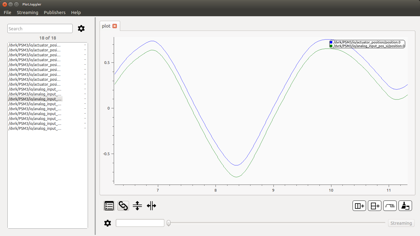
rosrun plotjuggler PlotJugglerIn PlotJuggler, import your ros bag, select all signals and then drag-and-drop the actuator and pot for the joint(s) you want to look at. You can also start ROS streaming in PlotJuggler and select the signals you want to plot. In the following example, there's is a small calibration offset:
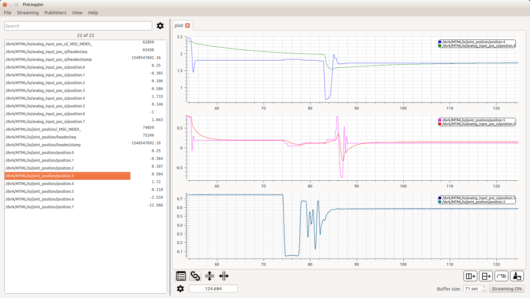
In this example, both joint 4 and 5 potentiometers have a significant delay:
From there you can see if the issue is:
- Garbage values, something is likely broken
- Vertical offset or "stretch", you should probably re-calibrate your potentiometers
- Horizontal offset. The pot is likely too slow and you can fix this by increasing the "Latency" in the XML configuration file

Community
Getting Started
- First Steps
- Software installation
- Controller Connectivity
- Configuration files
- Hardware Setup
- Calibration
- Classic/Standard
- Si
- Examples
Advanced
- Software Architecture
- Application Development
- APIs
- UI Customization
- Teleoperation
- Kinematics Simulation
- Potentiometer Issues
- Development Branches
- Release Checklist
- Projects
- Controllers/versions
- E-STOP Wiring
- Full da Vinci System
- Head Sensor
- Foot Pedals
- Video
- Instruments
Miscellaneous
- Frequently Asked Questions
- User manuals Classic Si
- QLA Heat Sink
- Build w/o ROS Linux Mac
- cisst
- JHU
Deprecated