Communication layer API for computer vision (CV) to connect with control board
CV requirement for python version: 3.6.9
Reference: https://www.cs.cmu.edu/~16385/s17/Slides/11.1_Camera_matrix.pdf
Alternative IMU solutions:
- Camera must have its own IMU to measure its orientation. The orientation of camera frame is different from the orientation of control board IMU frame. Therefore, the target 3D point in camera frame must be converted into control board IMU frame. We are free to do it on CV side before sending or control side after sending. For now, it's easier to do it on control side, because it's easier for Ctrl to find the transformation matrix during calibration process.
- (Current setup) CV stores a hardcoded transformation matrix to do the conversion before sending to Ctrl board
- CV and Ctrl can share the same IMU. In this case, the orientation relationship with Camera and IMU should be hardcoded into CV, and target position should be converted into IMU frame before sending to Ctrl. Finally, Ctrl would not need to do any conversion.
Control board should use its current IMU location, target location sent by CV and initial projectile speed setting to calculate the projectile direction as the setpoint for gimbal motors.
Typically, we fix control board to the same orientation as the cannon, so omit the difference in cannon frame and control board IMU frame.
@TODO: To have good precision, control would better have a cascaded feed-forward & feedback control strategy to ensure the initial projectile speed. One of the feedbacks should be Referee system's projectile speed measurement. Its actuator would better be CAN-bus controlled M3508 without reduction gears. We must wait until friction wheels to reach certain speed before loading projectiles to shoot every time. And relation between this wheel speed and the actually measured initial speed should be estimated and feed-forwarded for future shots.
(WIP)
(WIP)
(WIP)
- Unit of all timestamps is ms, format is uint16_t. It's defined by timestamp = raw_timestamp - sync_time. if raw_timestamp overflow and becomes smaller than sync_time, timestamp = raw_timestamp - sync_time + 0x10000 to avoid negative number. Exception are TranDelta and TranDelta_MA, which are int16_t, because it may become negative when control board's tick updates slower than CV.
- Reason for CV to request for CvSyncTime at around the 8th step:
CV may send multiple ACKs to multiple set-mode requests that are stuck in the buffer before CV starts processing. CV will memorize the CvSyncTime of the last ACK, while control board may not, since some messages may be lost caused by turn around time of DMA controller.
Therefore, to correlate, control board must have latest CvSyncTime stored and sent to CV when requested. - TranDelta history should be cleared every time Control board boots up.
- For consistency, all timestamps within package headers should be synchronized, i.e. offseted by SyncTime, even before the synchronization process, where . For example, for control board, the timestamp should be CtrlTimestamp(Tx) - CtrlSyncTime. For CV, the timestamp should be CvTimestamp(Tx) - CvSyncTime.
- For all msgs control receives from CV, update TranDelta_MA and its history. Newest TranDelta = CtrlTimestamp(Rx) - CtrlSyncTime - MsgTimestamp, except for the ACK msg where calculation is different as illustrated in the diagram below.
sequenceDiagram
    autonumber
    loop while True
        Note left of Control: Communication establishment: time synchronization
        loop every 1.5 seconds
            Control->>CV :Set-mode request: Auto-aim or Auto-move on<br/>Including ReqTime = CtrlTimestamp(Tx) - CtrlSyncTime
            break when ACK is received
                activate CV
                CV-->CV :CvSyncTime = CvTimestamp(Tx)<br/>ExecDelta = CvSyncTime - CvTimestamp(Rx)
                deactivate CV
                CV->>Control :ACK<br/>Including Timestamp = CvTimestamp(Tx) - CvSyncTime = 0<br/>Payload: CvSyncTime, ExecDelta and ReqTime
                Control-->Control: TranDelta = (CtrlTimestamp(Rx) - CtrlSyncTime - ReqTime - ExecDelta)/2<br/>TranDelta_MA = MovingAverage(TranDelta)<br/>CtrlSyncTime = CtrlTimestamp(Rx) - TranDelta<br/>Save CvSyncTime
            end
        end

        opt if CV responds to all the set-mode requests stuck in the buffer before it starts processing
            activate CV
            CV-->CV :CvSyncTime = CvTimestamp(Tx)<br/>ExecDelta = CvSyncTime - CvTimestamp(Rx)
            deactivate CV
            CV->>Control :ACK<br/>Including Timestamp = CvTimestamp(Tx) - CvSyncTime = 0<br/>Payload: CvSyncTime, ExecDelta and ReqTime
            Control-->Control: TranDelta = (CtrlTimestamp(Rx) - CtrlSyncTime - ReqTime - ExecDelta)/2<br/>TranDelta_MA = MovingAverage(TranDelta)<br/>CtrlSyncTime = CtrlTimestamp(Rx) - TranDelta<br/>Save CvSyncTime
        end

        loop
            CV->>Control :Request Info:TranDelta & CvSyncTime
            Control-->Control :Update TranDelta and TranDelta_MA
            break when feedbacks for all requested info are received
                Control->>CV :Info:TranDelta_MA
                Control->>CV :Info:CvSyncTime
            end
        end

        Note left of Control: Cv Command Control Board
        loop every MIN_TX_SEPARATION_SEC<br/>until CV msg interval > 1 sec,<br/>for which Ctrl would think CV is offline
            CV->>Control :CvCmdMsg<br/>(Enemy 3D location in Camera frame)<br/>(chassis 2D target location in Camera frame)
            par
                Control-->Control :Update TranDelta and TranDelta_MA
            and
                CV-->CV :Wait for MIN_TX_SEPARATION_SEC
            end
            opt Every 500 iterations
                CV->>Control :Request info:TranDelta
                Control-->Control :Update TranDelta and TranDelta_MA
                Control->>CV :Info:TranDelta
                CV-->CV :Update TranDelta for Kalman filter
            end
        end
    end
Calibration process for transformation matrix between camera frame and control board IMU frame
(not in use right now)
sequenceDiagram
    Control-->Control:Calibration process started by remote controller
    Control->>CV :Set-mode request (Auto-aim & Auto-move off)
    CV->>Control :ACK
    loop At every step of gimbal calibration,<br/>i.e. when gimbal is aiming at <br/>bottom, top, left, right directions
        Control-->Control:After Ctrl board IMU signal is stable for 0.5 seconds
        Control->>CV :Request Info: Camera IMU data
        CV->>Control :Info: Camera IMU data
    end
    Control-->Control: Solve for and save transformation matrix
flowchart LR
    subgraph CtrlBoardC["Control Board"]
        subgraph CtrltoCv-UART["UART for CV"]
            Ctrl-CtrltoCv-VCC["5V"]
            Ctrl-CtrltoCv-Rx["Rx"]
            Ctrl-CtrltoCv-Tx["Tx"]
            Ctrl-CtrltoCv-Gnd["Gnd"]
        end
    end

    subgraph CV["Computer Vision Board"]
        subgraph CV-CtrltoCv-USBtoTTL["USB-to-TTL (5V level)"]
            CV-CtrltoCv-VCC["5V"]
            CV-CtrltoCv-Rx["Rx"]
            CV-CtrltoCv-Tx["Tx"]
            CV-CtrltoCv-Gnd["Gnd"]
        end
    end

    Ctrl-CtrltoCv-VCC~~~|"#quot;5V#quot; may be different,\nso do not connect"|CV-CtrltoCv-VCC
    Ctrl-CtrltoCv-Rx---CV-CtrltoCv-Tx
    Ctrl-CtrltoCv-Tx---CV-CtrltoCv-Rx
    Ctrl-CtrltoCv-Gnd---CV-CtrltoCv-Gnd
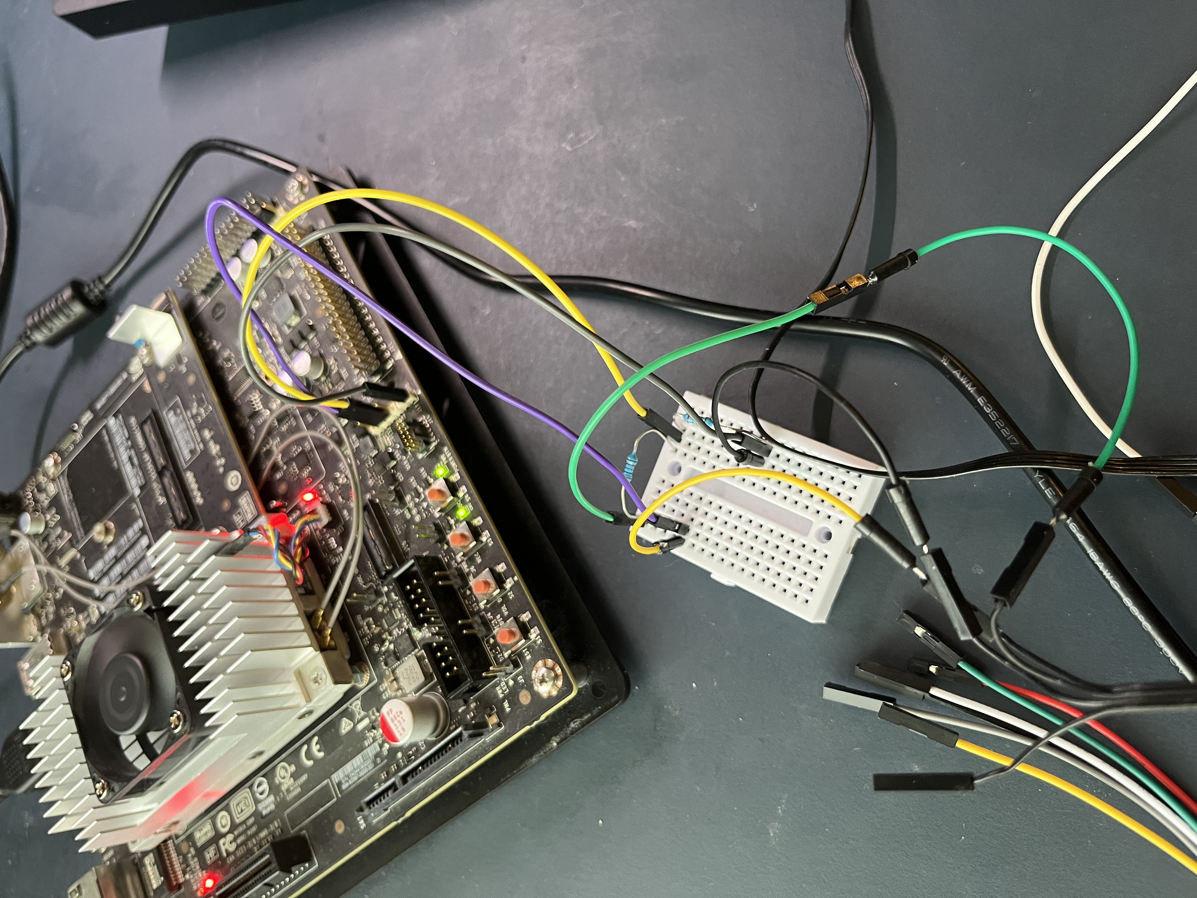
This picture is obsolte, please use USB-to-TTL dongle instead. Because the UART Tx port on Jetson TX2 is not working properly. Its current output capacity is too low that it must use a MOSFET circuit to drive the control board's Rx pin.
- Serial Port : /dev/ttyTHS2
- Resistors below converts control board's 5V level Tx signal down to 3.3V via voltage divider.