Hardware Version 1.0 to 2.0
Version numbers on this project get a bit out of hand, but this roughly covers the first version of the AutoChanger. The geometry is pretty much nailed down and subsequent versions update the features on the controller board.
Version 1.0 used an Atmega 328P chip on board. It was really not reliable and I had a ton of trouble getting them to flash code. Version 1.3 uses an Arduino Nano controller and has a single WS2812 LED to indicate the status and location of the carriage. This was an advantage because I could remove the module and program it if it started playing up. Version 2.0 keeps the Arduino Nano controller, but included an OLED and a rotary encoder.

This version includes a roll over bent acrylic front plate that was a giant pain in the butt to make at home.

Confusingly, I named the last compatible software for this hardware "Version 2.0", mainly because it was a complete re-write. It featured the ability to reprogram the sequence (A feature Sarah did not want, need or use) and that was kind of cool.
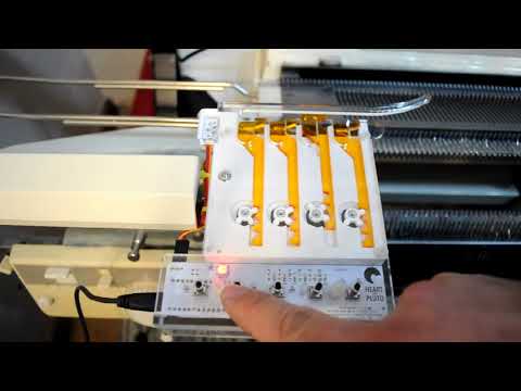
▶ [Watch on YouTube](https://www.youtube.com/watch?v=xEOuRG-m6oA)

__Version 2.0 hardware, Arduino Nano with OLED
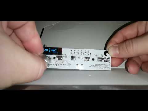
▶ [Watch on YouTube](https://www.youtube.com/watch?v=Tv0mWhDU24A)
The 3+1 blog posts explain how the project got to that state:
Building a better colour changer - Part 1 - Designing Hardware
Building a better colour changer - Part 2 - Firing the lasers
Building a Better Colour Changer – Interlude – The KRC-1000E
Building a Better Colour Changer – Part 3 – Revising the design
- Arduino Uno compatible.
- Automatically change between 4 different colours.
- Audio guides.
- Programable colour order.