EcoSwitch Installation and Casing
- About The Project
- Hardware Module Overview
- Designing the Casing for the Device
- EcoSwitch Device Installation Steps
- Contact
The EcoSwitch device's installation involves assembling and mounting it on the Fan Control Unit (FCU). The original problem statement required the EcoSwitch device to be safely mounted on the FCU dial and tamperproof.
Device Concept:
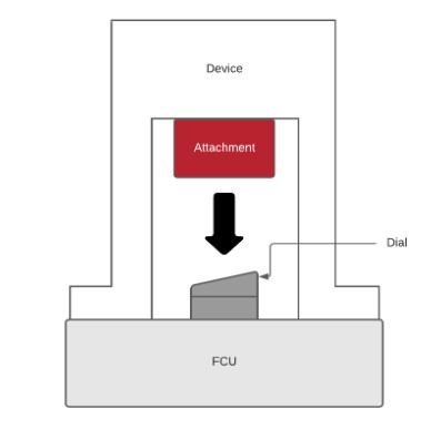
The device comes with a battery pack connected to a rectangular box which is the circuit and driver for the device. Also, there should be another longer rectangular box with four M4 screws and two M3 screws. The installation steps below show how to assemble the whole device and mount it on the top of the FCU dial. Also, instructions for designing these boxes are listed below.
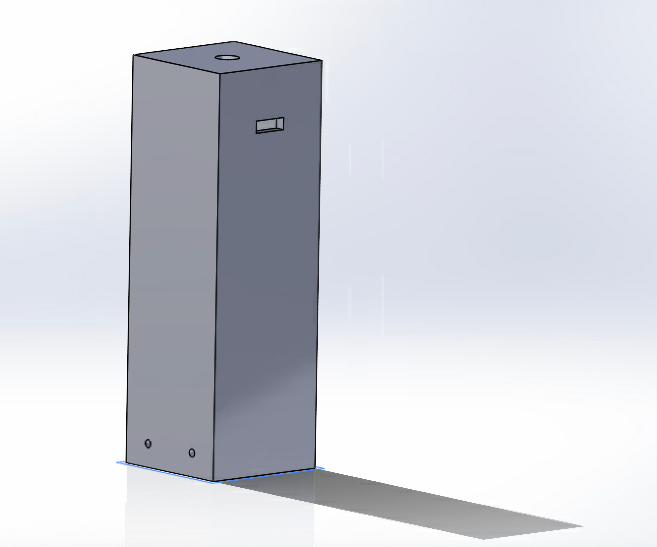
All the designs are done using 3D modeling in Solidworks. The first part is the case for the stepper motor. The purpose of this case is to stabilize the stepper motor when it turns. Therefore, the inner square dimension for the case should be close to the overall dimension of the stepper motor with around 10% tolerance for the error in 3D printing. Also, there should be holes besides for screws to stabilize it and spaces for the wire to come out of the case. The 3D model for this case is here: casing_for_motor. The drawing of this 3D model is here: drawing_case_for_motor.
The following diagram is a perpective view for this case:
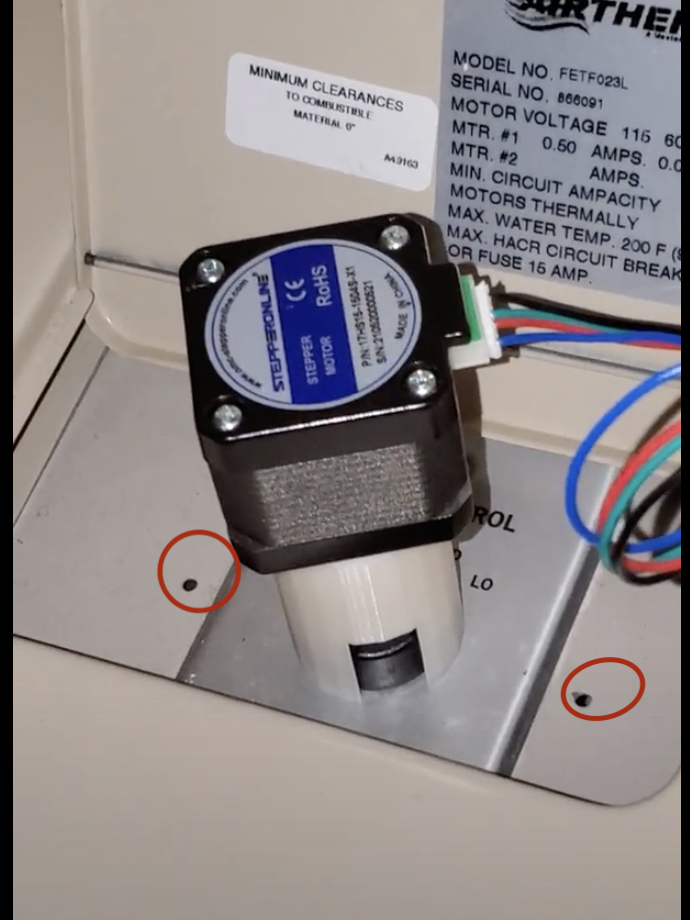
The motor case is connected with two T-bars beside for stabling the whole device in the two pivots point near the FCU device. The actual FCU device looks like the following diagram with a red circle as the pivot point:
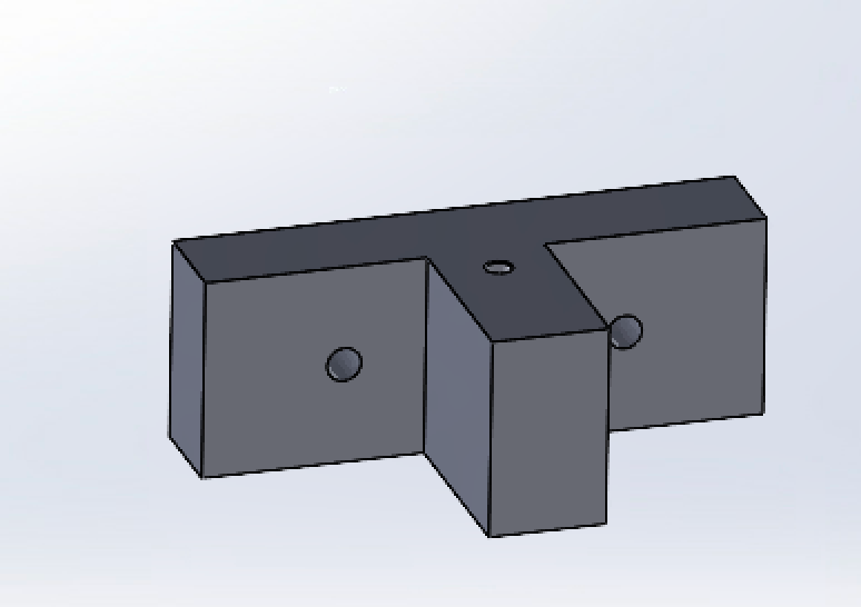
The T-bar has a hole on the top which should be the same size as the pivot holes. Also, two holes beside should have the same dimensions as the side holes in the motor case. The 3D model for the T-bar is here: 3Dmodel_for_T_bar. The drawing of the T-bar is here: Drawing_for_T_bar. The following diagram is a perspective view for this T-bar:
The second case is used to cover the whole circuit and driver. It connects with battery outside and motor in the motor case.
Each EcoSwitch device will come prebuilt with a motor, an attachment, a circuit board within the rectangular outer shell, and a battery pack. The device will be mounted on the FCU dial and securely attached to the knob. Then, batteries are needed in the battery pack to power the device and assemble it as follow:
- Put two T-shape bars beside the rectangle box.
- Use four M4x20 mm screws and drill them inside the two holes of the T-shape bars. Also, fix the M4 screw locks at the end to stabilize the screws.
- Use two M3x20 mm screws to drill on the top hole of the two T-shape bars.
- Fix the M3 screw locks at the end to stabilize the screws.
If there are any further questions about the application project, please contact the lead developer via email.