Repository navigation
Example Gallery
examples/campus/
is a complete, self-contained capture set for a six-switch campus: two core switches
joined by a port-channel, two distribution switches, two access switches, plus an edge
router, two ESXi hosts and a third access switch that no capture covers — ten devices in
total. It is the source of every diagram below except the last two, which come from the
smaller
examples/hsrp-quad/
and
examples/bgp-edge/.
Every image is nettopo's own output, and the .drawio files behind them are committed
next to the captures. Regenerate them with:
nettopo l2   -i examples/campus -o examples/campus/diagrams
nettopo l2   -i examples/campus -o examples/campus/diagrams --endpoints network-only --link-mode port-channel
nettopo stp  -i examples/campus -o examples/campus/diagrams --all
nettopo hsrp -i examples/campus -o examples/campus/diagrams --all
nettopo hsrp -i examples/hsrp-quad -o examples/hsrp-quad/diagrams --all
nettopo bgp  -i examples/bgp-edge -o examples/bgp-edge/diagrams
The PNGs are exports of those same files, made with
draw.io Desktop's CLI — leaving out -t/--transparent is what
gives them a white background:
drawio -x -f png -s 2 -b 20 -o examples/campus/diagrams/l2/l2_full.png examples/campus/diagrams/l2/l2_full.drawioA PNG is a snapshot. Open the
.drawioin draw.io for the editable diagram — draggable nodes, and the hover tooltips that carry a port-channel's member interfaces.
Ten nodes, thirteen links; each link is labeled with the physical interface at each end,
and each node is drawn with the icon for its role. The role comes from the chassis the
device reports — cisco C9500-16X for the core pair, cisco WS-C2960X for the access
switches, cisco ISR4331/K9 for edge-rtr, VMware ESX for the two ESXi hosts — falling
back to the capabilities its neighbors advertised over CDP/LLDP when the platform names
nothing recognizable. A legend names every role the diagram actually contains.
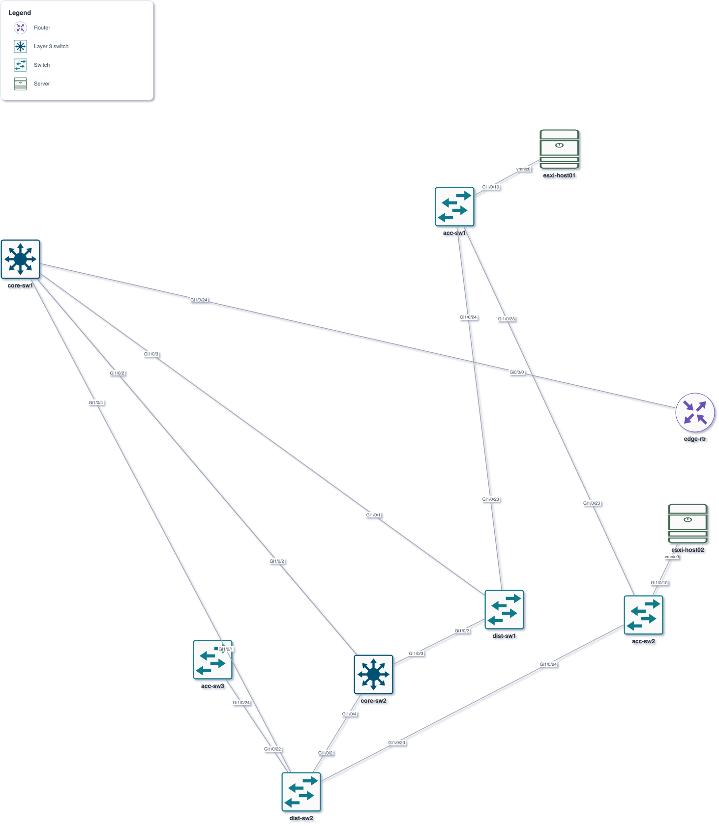
Source: l2/l2_full.drawio.
The same topology with the two flags applied: the ESXi hosts are gone (they advertise
neither Router nor Switch), and the two physical core links have collapsed into the
single bundle both switches call Po1. Its member interfaces move into the link's
draw.io hover tooltip (Gi1/0/1 — Gi1/0/1, Gi1/0/2 — Gi1/0/2), which the PNG below
cannot show but the .drawio does. Eight nodes, ten links.
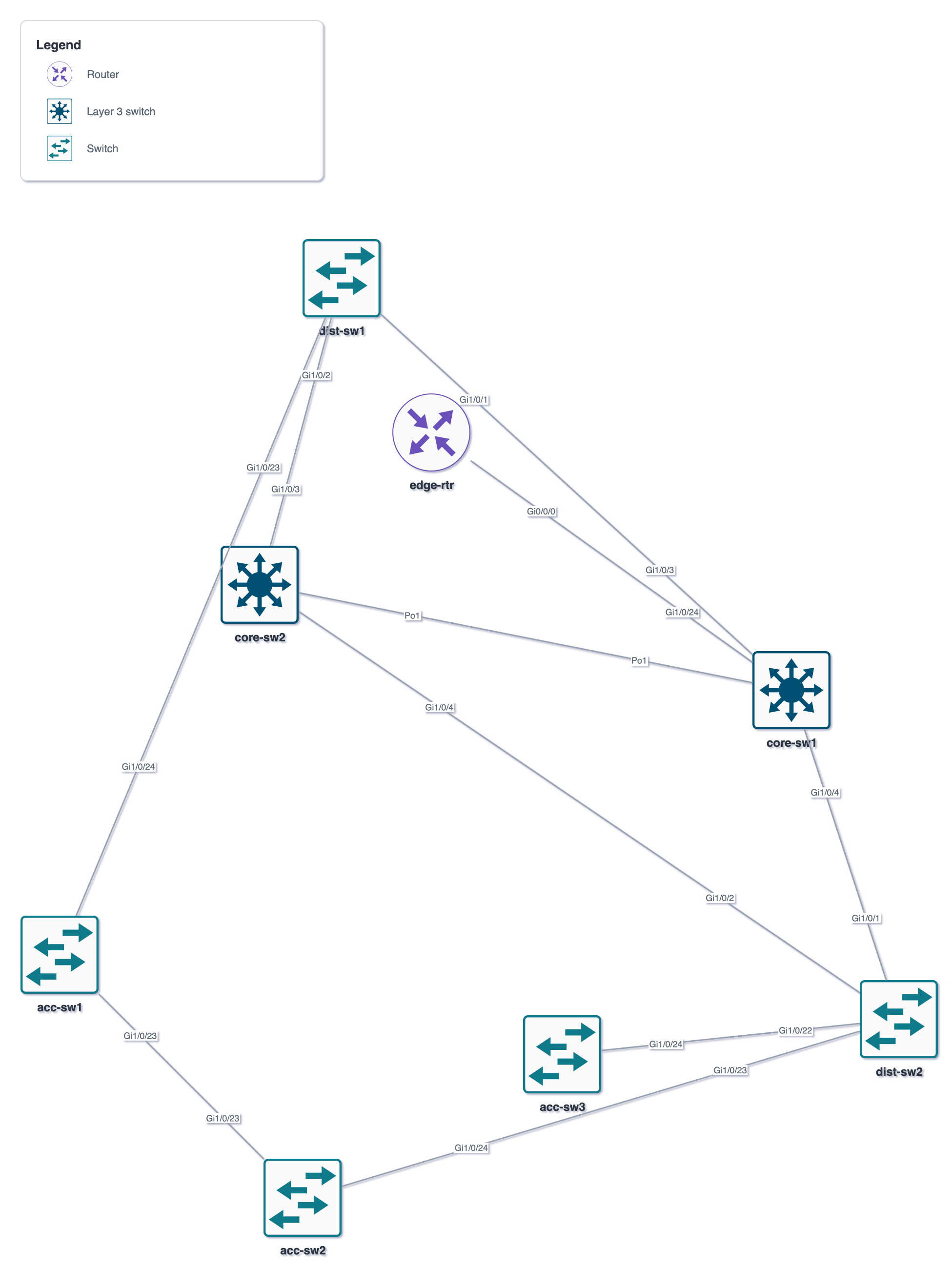
Source:
l2/l2_network-only_port-channels.drawio.
Switches only: edge-rtr and the two ESXi hosts are gone. core-sw1 is the root bridge
(gold card); every other node carries its bridge MAC and effective priority.
acc-sw3 has no capture of its own, so it is drawn faded, in italics, and labeled with its
name alone — it is included because the port facing it (dist-sw2 Gi1/0/22) is not an Edge
port, the same filter that keeps the ESXi hosts out. Green links forward at both ends;
red links have a blocked end. The three blocked ports are what breaks the two loops in
the topology. The legend lists only the markings this particular tree uses.
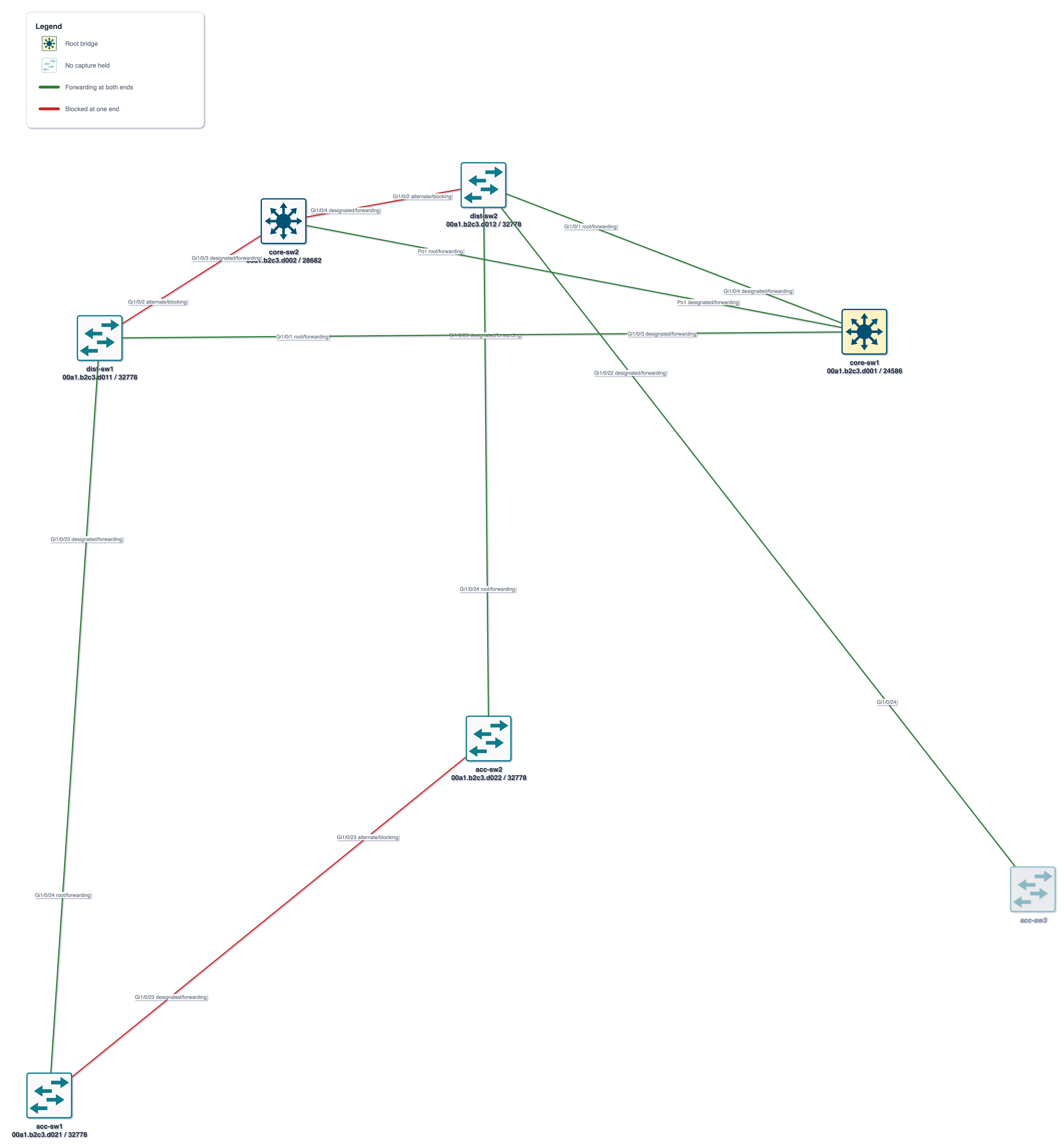
Source: stp/stp_vlan10.drawio.
Note that the core-to-core link is drawn once, labeled Po1: spanning tree treats a
bundle as one logical port, and show spanning-tree only ever names Po1 while
CDP/LLDP only ever name Gi1/0/1/Gi1/0/2. show etherchannel summary is what joins
the two — drop it from core-sw1.txt/core-sw2.txt and this link disappears.
VLAN 30 is rooted on core-sw2 (spanning-tree vlan 30 root primary, with core-sw1
as secondary). Same devices, same cabling, different tree: the blocked ports move from
Gi1/0/2 to Gi1/0/1 on both distribution switches, and the core port-channel reverses
role. This is why the view renders one diagram per VLAN rather than a single "STP
diagram".
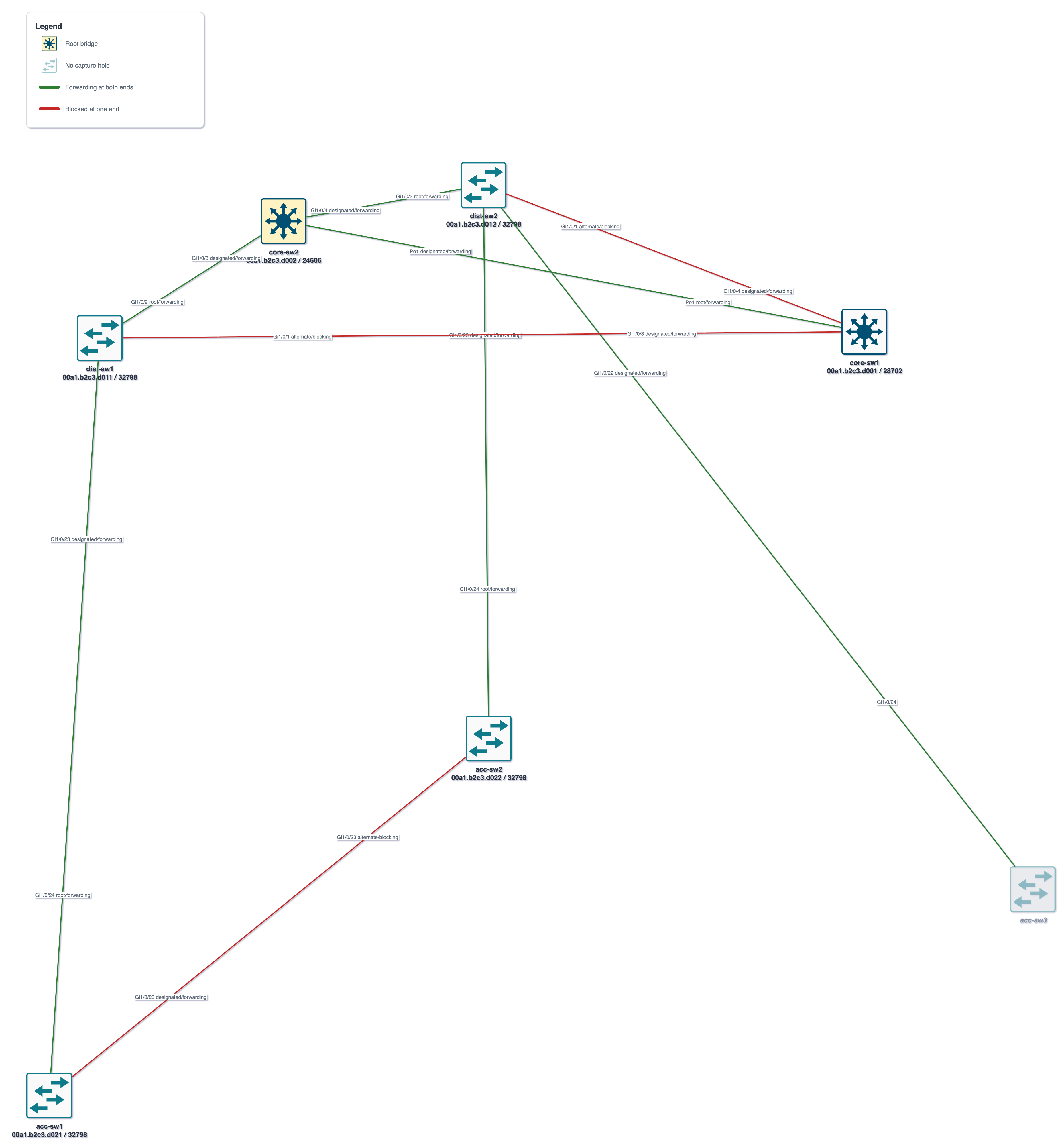
Source: stp/stp_vlan30.drawio.
VLANs 10, 20 and 99 produce the identical picture, which is exactly what --group-mode
exists for — see
what --group-mode does to this capture set.
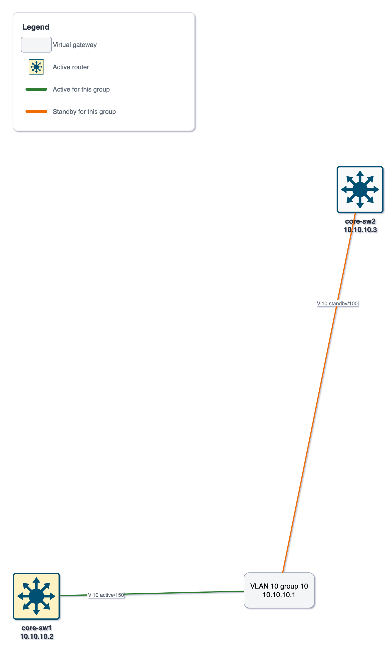
The core pair also runs HSRP on VLANs 10, 20 and 30, aligned with the spanning trees:
core-sw1 is active where it is root, core-sw2 is active for VLAN 30. The rounded box
is not a device — it is the virtual gateway 10.10.10.1, the address the VLAN's hosts are
configured with. Each router carries its own SVI address (10.10.10.2, 10.10.10.3)
under its name, so both halves of the first hop are on the page, and links to the gateway
labeled with its SVI, HSRP role and priority: green for the router currently answering,
amber for the one waiting to take over. The active router carries the same gold card the
STP view gives a root bridge.
Source: hsrp/hsrp_vlan10.drawio.
There is no --group-mode here, unlike stp: nettopo hsrp -i examples/campus --all
writes hsrp_vlan10, hsrp_vlan20 and hsrp_vlan30, always one per VLAN. VLANs 10 and
20 have the same active/standby split, so the STP view would happily group them — but
their gateways are 10.10.10.1 and 10.10.20.1, and every router holds a different SVI
address in each. There is no picture that covers both without either hiding one VLAN's
addresses or printing two of everything.
A two-switch gateway pair is the common case, but an HSRP group can have any number of
members and only ever two of them are named: one active, one standby. Everybody else sits
in Listen, watching the hellos and waiting for an election.
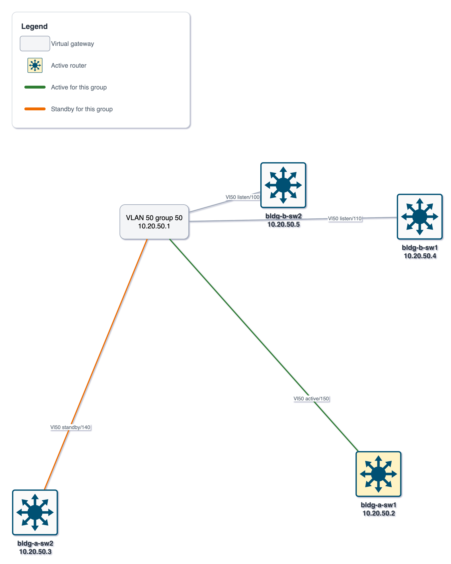
examples/hsrp-quad/
is a small capture set for exactly that — VLAN 50 spans two buildings, each with a pair of
layer-3 switches, and all four share one group:
| Router | SVI address | Priority | State |
|---|---|---|---|
bldg-a-sw1 |
10.20.50.2 |
150 | Active — highlighted, green link |
bldg-a-sw2 |
10.20.50.3 |
140 | Standby — amber link |
bldg-b-sw1 |
10.20.50.4 |
110 | Listen — neutral link |
bldg-b-sw2 |
10.20.50.5 |
100 | Listen — neutral link |
Source: hsrp/hsrp_vlan50.drawio.
The two listeners are why every node carries its own address and not just the virtual
one. show standby brief reports the active and standby routers by address — that is
what its Active and Standby columns are — but it never names anyone else, so
10.20.50.4 and 10.20.50.5 appear nowhere in any of the four captures' HSRP output.
They come from show ip interface brief instead, which is why that command is worth
capturing even though the HSRP view needs no topology. The legend lists only the two
colors this group uses; a neutral link means the router is in the group but neither
answering for it nor next in line.
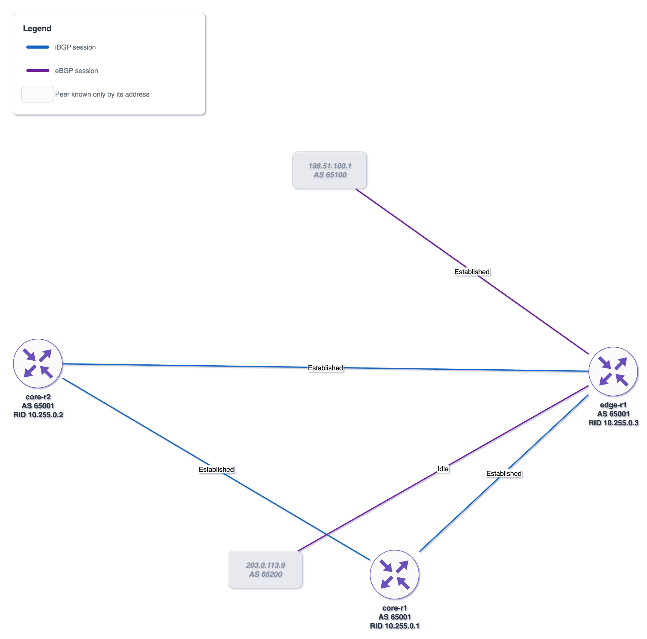
The campus switches run no BGP, so this one comes from
examples/bgp-edge/:
three routers in AS 65001 — two core, one edge — fully meshed over iBGP, with edge-r1
holding the two eBGP sessions to the outside.
Source: bgp/bgp.drawio.
Each router carries its AS number and its BGP router ID under its name — here the
loopback each one uses as its identity, which is also what makes the matching below work.
Each session is drawn once, though the mesh's three sessions are each reported twice —
once by the router at each end. show ip bgp summary names the far end by IP and nothing
else, so nettopo matches each peer address against the addresses the captures report in
show ip interface brief: where it finds one, the two reports become one link between two
named routers. 198.51.100.1 and 203.0.113.9 match nothing — no capture covers them —
so they keep a node of their own, faded like any other device known only through someone
else's report, and labeled with the address and AS number the session named them by.
The state on each link is read from the summary's last column, which IOS overloads: it
prints a prefix count for a session that is up and a state word for one that is not, so a
count is reported as Established and anything else verbatim — 203.0.113.9 here never
came up at all. bgp.csv carries the same data per reported session, both directions
included.