Repository navigation
A clocked digital circuit
A four-bit counter is a small circuit with state. It starts at zero, increments when enabled, holds its value otherwise, and resets synchronously to zero. In proarrow, one description of its connections supplies a simulator, diagrams, and a Verilog implementation.
The notation is Proarrow.Tools.SMC, introduced in Programming with monoidal categories. Variables name wires, applying an arrow connects a component, and a recursive binding feeds an output back to an input.

The two inputs are single bits, labeled b₁. The output and the feedback wire carry a four-bit word, b₄. The register D4 (0) stores that word, initially zero.
Read the feedback loop starting at the register's output. The incrementer adds one, discarding overflow. The first multiplexer chooses between that incremented value and the current count, under the enable input. The second chooses between zero and the first result, under reset. Its output is the register's next input, so reset takes priority over enable.
With the concrete components, these connections can be written as:
counter :: Bit ** Bit ~> Word4
counter =
  toSMC @(F Bit :** F Bit) @(F Word4) \(enable, reset) -> SMC.do
    rec count <- register4 0 -<
          (mux4 -< (reset, zero4 -< unit,
            mux4 -< (enable, increment -< count, count)))
    returnA -< count
mux4 is the four-bit multiplexer shown in the diagram: it chooses its second input when its first is true, and its third otherwise. increment adds one, zero4 -< unit supplies the zero word, and register4 0 is the box labeled D4 (0). The types Bit and Word4 correspond to the b₁ and b₄ wires.
The rec binding lets the expression use count as its own input. Each occurrence refers to the same register output. Sharing that variable introduces fan-out; it does not instantiate another register. The diagram above interprets the components as named boxes in SVG.
A feedback wire alone has no delay. The Circuit category's trace connects an output to an input, and register supplies the state that makes this counter a clocked circuit. Its current output is available before its input becomes the next output.
For an enable bit e, reset bit r, and current count n, the next clock edge produces:
if r then 0 else if e then (n + 1) `mod` 16 else n
Simulation observes the output before each clock edge, then updates all registers simultaneously. The initial sample is therefore zero even if reset or enable is already set. Reset is synchronous: it controls the value after the edge.
An inverter connected directly to itself has no register to break the instantaneous dependency. prepare rejects such an observable combinational cycle before simulation. Verilog generation uses the same validation.
Each word-sized component operates on a bundle of four bits:
type Word4 = Bit ** Bit ** Bit ** Bitincrement is a ripple-carry network of XOR and AND gates. mux4 applies a bit multiplexer to each position, sharing the selector. register4 0 puts four initially false one-bit registers side by side. Bit zero is the least significant bit.
Here is the expanded network, read back from its open hypergraph in parallel layers:

The graph records the connections independently of how the source expression was assembled. Reading it back with layered (tracedWith copyDiscard) groups independent components into tensors and preserves the feedback. The compact picture keeps the word-sized components visible; this one exposes their internal wiring. These layers describe wiring dependencies, not successive clock cycles: all four registers update on the same edge.
The example enables the counter long enough to wrap from 15 to zero, holds it for three cycles, then resets it and resumes counting.
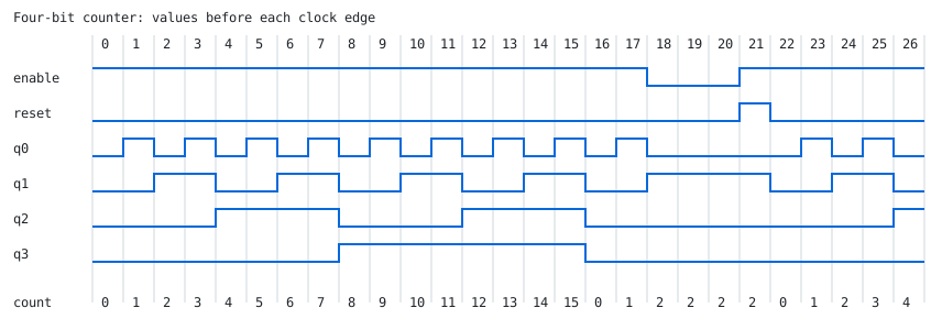
Each column shows the controls and output before that cycle's clock edge. A control change affects the count in the following column. The decimal count along the bottom makes the wrap, hold, and reset visible without decoding the four bit traces.
netlist counter builds the bit-level graph used by simulation. toVerilog "counter" emits that graph with a clock input, two control inputs, and four output bits. Each register becomes a Verilog register with its declared initial value and a nonblocking assignment on the rising edge. For example, the first output bit uses:
reg w23;
// ...
initial w23 = 1'b0;
always @(posedge clk) w23 <= w19;
The wire numbers are local to the generated netlist. Initialization preserves the simulator's starting state; its synthesis support depends on the hardware target. The example also supplies a testbench that compares the generated circuit's outputs with the simulator's expected values.
From the repository root:
cabal repl test:test
Then in GHCi:
import Examples.Circuit
import Proarrow.Category.Instance.Circuit

demoOutputs
writeFile "/tmp/counter.svg" counterPicture
either fail (writeFile "/tmp/counter-gates.svg") simplifiedCounterPicture
either (fail . show) (writeFile "/tmp/counter-waveform.svg") waveform
either (fail . show) (writeFile "/tmp/counter.v") (toVerilog "counter" (netlist counter))
either (fail . show) (writeFile "/tmp/counter_tb.v") counterTestbench
With Icarus Verilog installed, run the testbench from a shell:
iverilog -g2012 -s tb -o /tmp/counter_sim /tmp/counter.v /tmp/counter_tb.v
vvp /tmp/counter_sim
The full example is Examples/Circuit.hs.
From a build pipeline to a parallel schedule uses the same graph read-back to expose concurrency in executable jobs.