Repository navigation
Browser demo
https://modbus-sim.steitec.net is a small Modbus network you can drive from
your browser: three devices behind one Modbus TCP gateway, built from the
Real-device profiles — an Eastron SDM630 energy meter (unit 1), an
Omron E5CC temperature controller (unit 2) and a SunSpec PV inverter
(unit 3). It is the same code that pip install modbus-sim gives you, running
in the page with Pyodide. Nothing runs on the server, and
the page sends nothing anywhere.
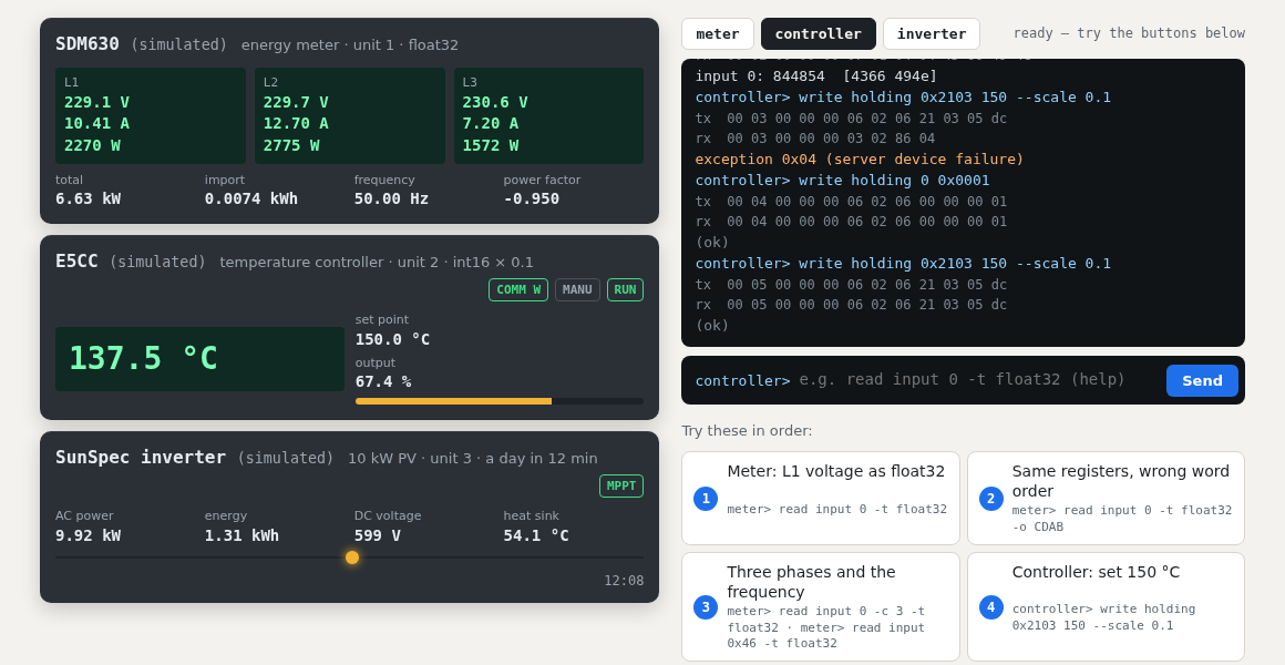
| Area | What it shows |
|---|---|
| SDM630 (top left) | the three phases (voltage, current, power), total power, imported energy, frequency, power factor. A yellow badge shows an active fault. |
| E5CC (middle left) | the process value, set point and output (MV), and the lamps COMM W (communications writing on), MANU (manual mode) and RUN/STOP. S.Err when the sensor is broken. |
| SunSpec inverter (bottom left) | the SunSpec operating state (MPPT, sleeping, fault …), AC power, energy, DC voltage, heat sink temperature, and the simulated time of day: a day passes in 12 minutes, starting at noon. |
| Terminal (right) | pick a device and type a command. Every request shows the Modbus TCP frame sent (tx) and received (rx), then the decoded values or the exception. ↑/↓ recall earlier commands. |
| Try these in order | eight buttons that type commands for you (see below). |
| Break something | four faults and a reset (see below). |
The fronts are redrawn every second from the simulator's state; the page computes nothing itself.
The commands are the read and write of the modbus-sim command line; the
unit ID comes from the selected device. Type help for the summary.
read  TABLE ADDRESS [-c COUNT] [-t TYPE] [-o ORDER] [--scale S]
write TABLE ADDRESS VALUE... [-t TYPE] [-o ORDER] [--scale S]
ident                        device identification (function 43/14)
-
TABLEiscoil,discrete,holdingorinput(orco,di,hr,ir). -
ADDRESSis the 0-based protocol address that goes into the frame. A manual's register 30001 isinput 0, 40001 isholding 0.0x…works. -
TYPEisuint16(default),int16,uint32,int32,float32,uint64,int64,float64orstring;-ccounts values, not registers. -
ORDERis the word order of 32/64-bit values:ABCD(default),CDAB,BADC,DCBA. -
--scaleturns the raw integer into an engineering value (raw × scale).
| # | Button | Sent | What happens |
|---|---|---|---|
| 1 | Meter: L1 voltage as float32 | meter> read input 0 -t float32 |
about 230.1 [4366 1741] — the SDM630 sends IEEE 754 floats, most significant register first |
| 2 | Same registers, wrong word order | … -o CDAB |
something like 1.65e+24: the same four bytes, decoded with the words swapped. This is the most common Modbus integration bug. |
| 3 | Three phases and the frequency |
read input 0 -c 3 -t float32, read input 0x46 -t float32
|
three voltages in one request; the frequency sits at register 30071 = address 0x46 |
| 4 | Controller: set 150 °C | controller> write holding 0x2103 150 --scale 0.1 |
exception 0x04 — the E5CC refuses writes until communications writing is switched on |
| 5 | Enable writing, then set 150 °C |
write holding 0 0x0001, then the set point again |
the operation command 0x0001 turns COMM W on; now the set point is accepted and the controller starts heating |
| 6 | Read the process value | read holding 0x2000 -t int16 --scale 0.1 |
the temperature, a signed 16-bit value in tenths of a degree |
| 7 | Inverter: find the SunSpec models |
read holding 40000 -c 2 -t string, … 40002 -c 2, … 40070 -c 2
|
'SunS', then model 1 (length 66), then model 103 (length 50) — the walk every SunSpec client does |
| 8 | AC current and its scale factor |
read holding 40072, read holding 40076 -t int16
|
a raw integer and the scale factor -2: the current is raw × 10⁻² A |
A few things to try by hand:
-
controller> write holding 0 0x0101stops the controller (operation command 01, info 01);0x0100starts it again.0x0901switches to manual, thenwrite holding 0x2600 50 --scale 0.1sets the output to 50 %. -
controller> read holding 0x2407— the upper status word. Bit 9 is communications writing, bit 8 is stop, bit 10 manual. -
meter> read holding 20 -t float32— the meter's Modbus address (set-up parameters are floats too). -
meter> read input 44 -t float32— reads 0: the SDM630 profile answers unlisted addresses with zeros.inverter> read holding 39990answers exception 02 instead: that map has no gaps to read. -
inverter> ident— device identification (function 43/14).
These are modbus-sim's fault injection, the feature you use in tests to check that your code copes with misbehaving devices (see Fault injection recipes).
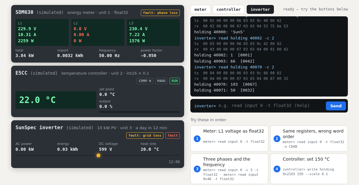
| Button | Fault | What your code would see |
|---|---|---|
| Meter stops answering |
no_response, once |
the next request gets no answer; after 2 s the terminal shows a timeout, as your master would |
| Meter loses phase L2 |
phase_loss phase 2 |
L2 reads 0 V and 0 A, the total power drops — does your monitoring raise an alarm? |
| Controller sensor breaks | sensor_break |
the process value reads 3276.7 (0x7FFF), bit 6 (input error) in the status, the output goes to 0 |
| Inverter loses the grid | grid_loss |
operating state 7 (fault), event bit 4 (grid disconnect), AC power and frequency 0 |
| Reset bench | — | all three devices back to power-on: faults cleared, controller writing off again |
pip install modbus-sim
modbus-sim serve --bench examples/real-devices.yaml     # Modbus TCP on 127.0.0.1:5020
modbus-sim read input 0 -t float32                       # unit 1, the meter
modbus-sim write holding 0 0x0001 -u 2                   # E5CC: communications writing on
modbus-sim inject meter phase_loss phase=2               # the fault buttons
The bench file is examples/real-devices.yaml.