Hadrware assembly instructions
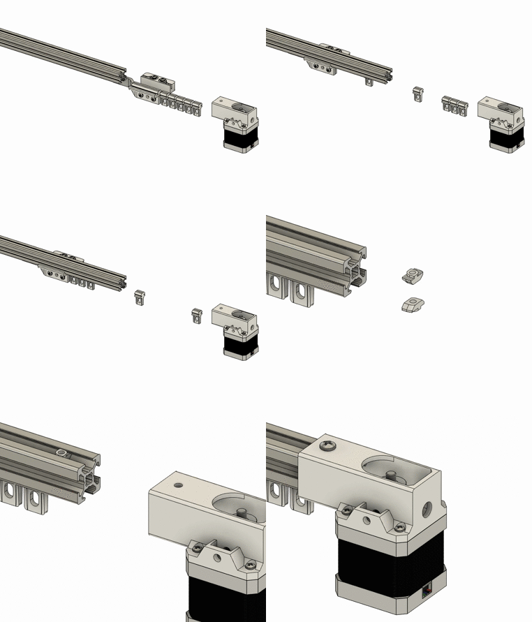
The first step is to assemble and and position the slider(s) that will move the curtain(s) along the
Parts list
- Belt clamp
- Slider
- Hook angled (dual action) or straight (single action)
- 2 x M4x25mm screws
- 2 x M4x14mm screws
- 4 x M4 nuts
First, fix the straight slider hook (part #) with the slider (part #) using 2 M4x14mm screws and nuts. With the two holes on the side facing the wall, the hook should point towards where the idler will be.
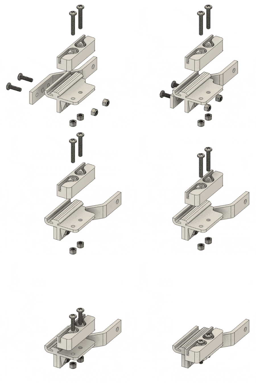
The double action variant needs a second slider to move the other curtain.
Parts list
- Slider
- Angled hook
- 2 x M4x14mm screws
- 2 x M4 nuts
Attach the angled hook to the slider using 2 screws and nuts.
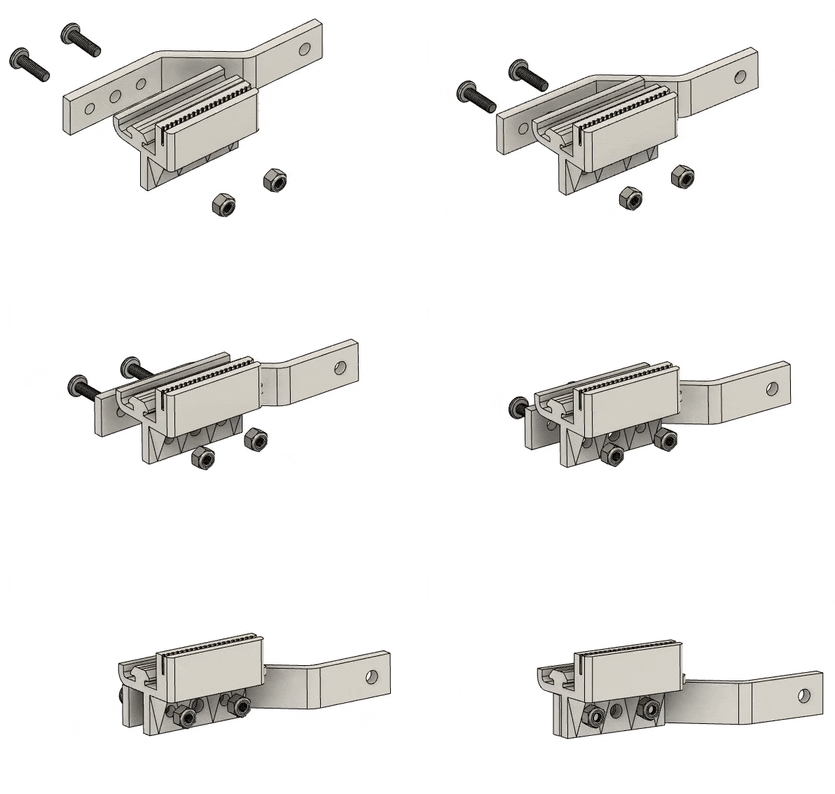
Then, fix the first angled slider hook (part #) with the slider (part #) using 2 M4x14mm screws and nuts. With the two holes on the side facing the wall, the hook should point towards the first slider. Fix the belt clamp (part #) using 2 M4x20-25mm and nuts, and slide the assembly on the underside of the profile from the opposite end where you inserted the first idler, with the hook pointing towards the first idler.
Slide the pulley in the idler bracket (part #), insert an M5x16mm screw and a nut on the underside.
Press the bearings on the bearing bushing (part #) such that the flanges are on the outside edges. Slide the assembly in the idler bracket (part #), insert an M4x16mm screw and a nut on the underside.
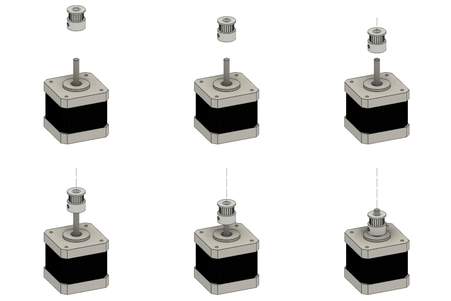
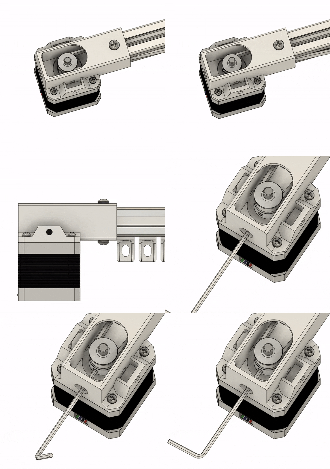
Fit the timing pulley on the motor shaft. Lightly tighten the screws on the pulley so that it does not slip. The vertical position on the shaft will be adjusted later
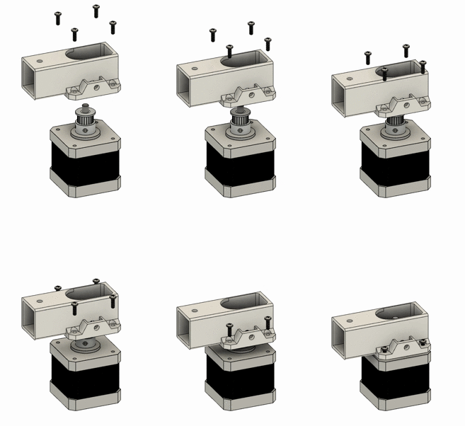
Next, fix the motor to the motor bracket using 4 M3x8mm screws.
Lay the motor bracket, profile and idler on a surface. You should only cut the timing belt after it is correctly positioned so you don't end up with a short belt. Start by sliding one end of belt in the motor bracket and around the timing pulley. Pull the belt and slide it through the idler bracket. Insert the idler onto the profile, pull the belt and attach it to one end of the belt fastener, and leave around 2-3 cm of length.
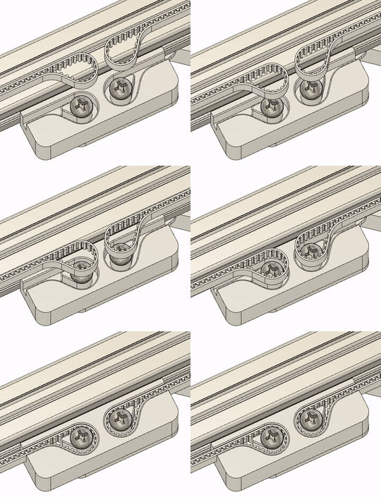
You can now cut the other end of the belt, making sure to leave 2-3cm of extra length
Put the two sliders together and align them so that they are centred on the track. Then, insert the belt on the belt clamp. The belt should be firmly attached to the clamp part.
Make sure you followed the instruction to assemble the electronics. Insert the led in the hole on the underside of the lower motor case (part #). Slide your power cord (and eventually the cable to the control switches) through the centre hole and connect it to the terminals of the power supply. Carefully slide the electronics in the case. Slide t-nut in the inserts on either side of the motor bracket. Position the top motor case on the motor bracket and slide the lower part of the case up. Insert M4x18mm screws and tighten them.
Simply insert t-nuts on the top side of the profile, place the bracket on top and tighten using M4x8mm screws