Repository navigation
Dimensions
Overall dimensions are always drawn; add chain dimensions for rows of parts, and a ruler or grid for positions.
| ISO 129-1 | ASME Y14.5 | |
|---|---|---|
| Dimension text | Above the line; vertical text reads from the right | Horizontal, in a break of the line |
| Arrowheads | Closed, 30° | Closed, 3:1 |
| Extension lines | Start at the part | Small gap from the part |

Dimensions sit 10 mm from the view, with 3.5 mm text (2.5 mm on A4 and Letter) and 3 mm arrowheads. Figures have a white background so lines never cross them.
Small dimensions: when the value does not fit between the extension lines, it moves just past them; when the arrows do not fit, they go outside, pointing in.
For rows of objects (shelves, posts, seats). Add a chain and set:
- Collection: the objects of the row;
- View: Top, Front or Side;
- Reference: the point of each object used as a station (Left Edge, Center, Right Edge, Origin);
-
Combine Equal Spacing: equal intervals written once as
5 × 600 = 3000; off, every interval is dimensioned; - Tolerance: intervals that differ by less than this percentage are merged (model imprecision);
- Positions: each station's coordinate from the world origin, under the chain;
- Architect Ticks (Style): oblique ticks instead of arrows. Ticks are also used where arrows do not fit.
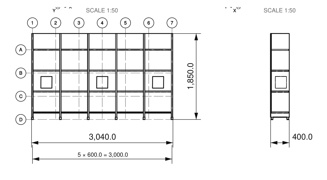
The chain under the front view above reads 5 × 600.0 = 3,000.0: five equal intervals of 600 mm.
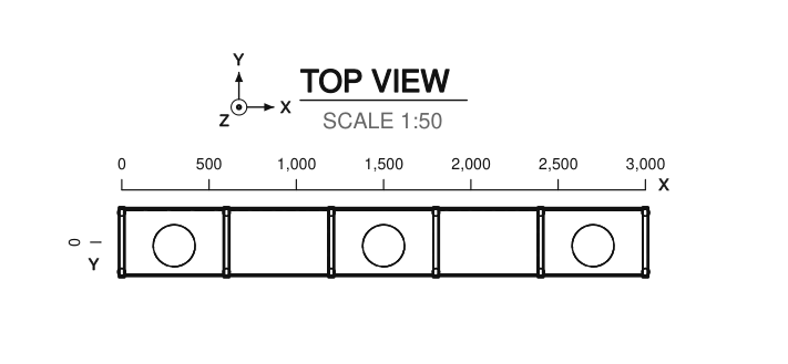
Ruler adds coordinate scales along the views; Grid adds an architect grid (A, B, C / 1, 2, 3). Set the Step (0 = automatic, about 10 intervals), the Origin object (world origin if empty) and the views (Top, Front, Side).
| Ruler | Grid |
|---|---|
 |
 |