Repository navigation
Section Views
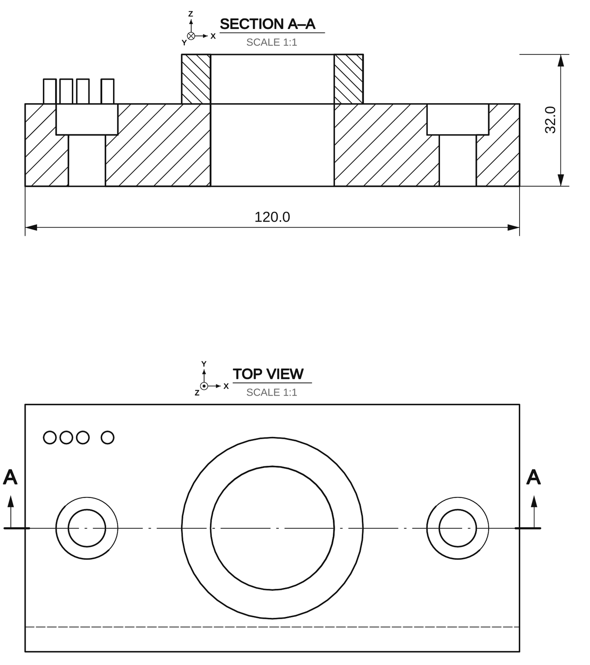
Section Views draws views cut by a plane, like a part sawn in two: the cut faces are hatched, and each cutting plane is shown on a neighbouring view with arrows and a letter (ISO 128-3, ISO 128-50). Up to three sections, one per view: front, side and top.
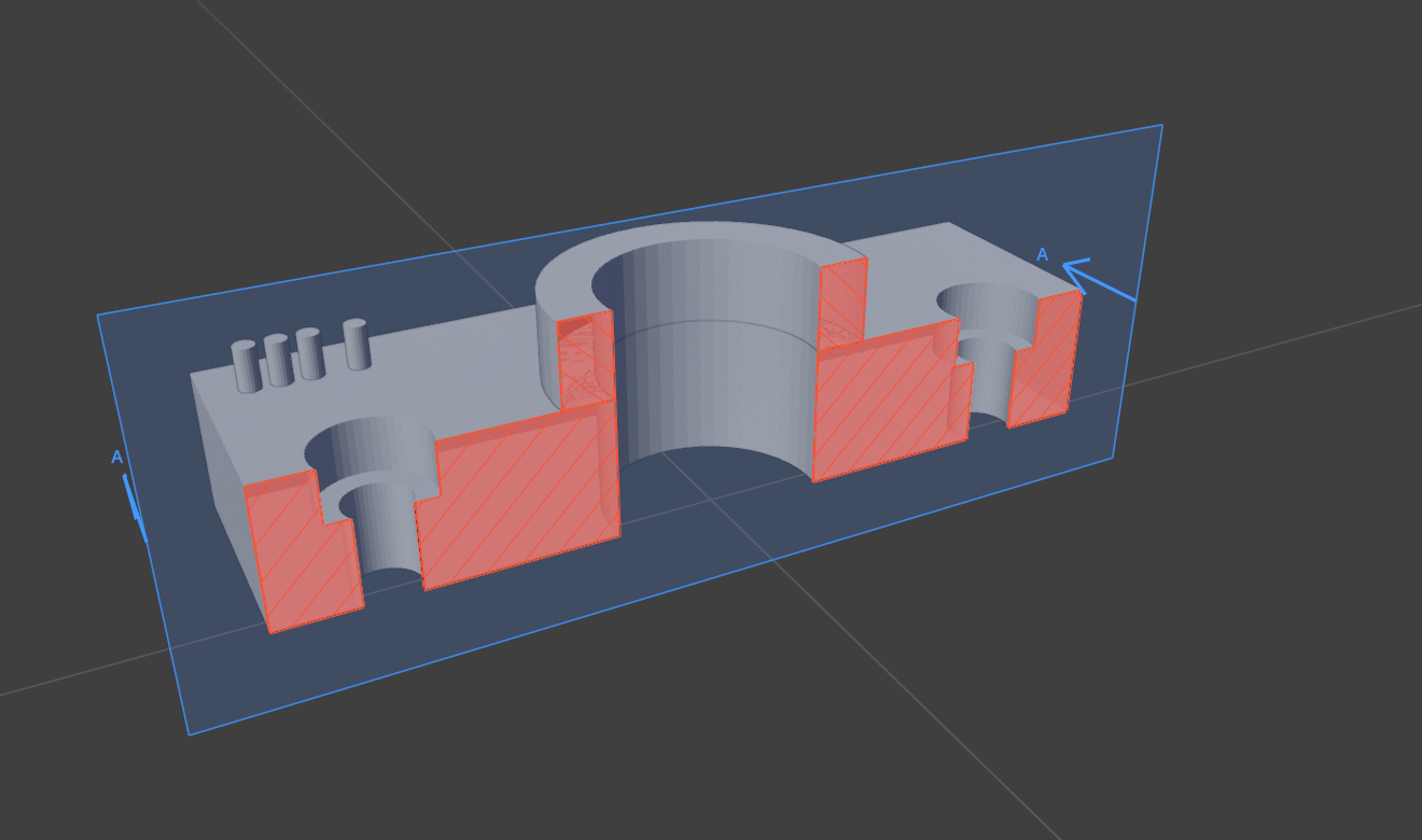
- Open Section Views (under Views) and click Front, Side or Top: a cutting plane goes through the middle of the parts, parallel to that view. The view is ticked in Views if it was not.
- Move the plane with G in the 3D View (it only moves along its axis), or with the Position slider: 0 % is the side the view looks at, 50 % the middle.
- Click Make Plan: the view is drawn cut, titled « SECTION A–A ».
A view already cut has its button greyed out. Choosing a view taken by another cut in the cut's settings swaps the two cuts.
- Click a cut to make it active: its plane is selected in the 3D View, ready for G. Selecting a plane in the 3D View does the same.
- The coloured square is the colour of the plane: click it to change it.
- The arrow button selects the plane; the cross removes the cut and its plane. Deleting the plane in the 3D View removes the cut too.
For the active cut:
- Letter: the name of the section (A gives « SECTION A–A »). I, O and Q are skipped when letters are given automatically, as they read like 1 and 0.
- Hatch (mm): distance between hatch lines on the sheet. It is reduced on small cut faces, and varied from one part to the next so that touching parts stay apart.
- Hide Cut Material: in the 3D View, the material in front of the active plane is hidden, as in its section. The other planes are drawn fainter.
-
Isometric: where the cutting planes are shown in isometric.
- Separate Page, Cut (default): an extra page « CUTTING PLANES », one isometric view per plane, with the material in front of the plane removed. The main isometric view stays clean.
- Separate Page: the same page, with whole isometric views and the plane drawn through them.
- Main Isometric View: all the planes on the isometric view of the drawing.
- None.
- Colored Planes: each plane in its colour on the drawing (cut lines, section titles, a light tint under the hatching, planes in isometric). Off: black and white, as in ISO 128.
- Only closed parts are hatched. A part with holes in its mesh is cut but not hatched; the panel and the drawing warnings name it.
- On heavy scenes (more than 1.5 million triangles), the cutting planes page uses whole isometric views, which are much faster to draw.
- Files made with Ichno Labs 0.5 get their cuts back when they open.