FlashFLoppy expansion board
With this board you are able to:
- place your OSD board inside the FlashFloppy case
- Easy connect your wires through the backside of your FlashFloppy case using Dupont cables
- Easy connect your OLED LCD
- Easy connect your USB2TTL while programming your firmware
The resistors that are needed can be solderd on the pcb.
Download FlashFloppy expansion board Eagle and Gerber files
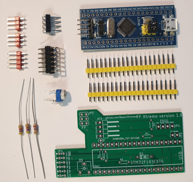
- Solder the two 4K7 and 10K resistors R1, R2, and R3.
- Solder the 500 Ohm potentiometer on R5
- Solder the two connectors with 20 pins each. Use straight headers and solder the shorter pins.
- Solder the connectors JP2, JP4 and JP5 with straight pins
- solder the connectors JP1 and JP3 with 90 degrees bended pins
- Desolder the four pins on the FlashFloppy pcb that connect your FlashFloppy to the Display.
- Place the FlashFloppy PCB over the six pins of JP5 inside the FlashFloppy case and solder them. It is important to have a little bit of free space between the two boards!
- Place the STM32F103C8T6 over the pin rows with the USB connector on the "USB" side as indicated on the pcb and solder all the pins.
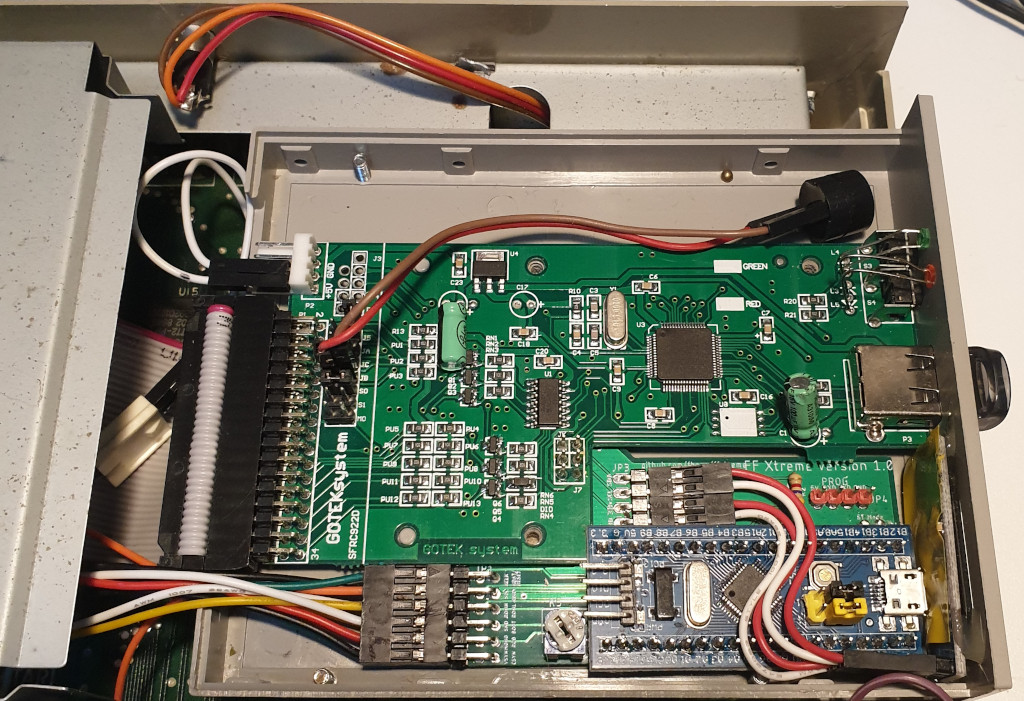
You now can connect your USB2TTL device to JP4. Just follow the Firmware programming section of Keir Fraser but use the firmware file from this project. Download firmware
Follow the wiring secion. Connections are:
- VSYN Vertical sync
- CSYN Horizontal sync
- RGB Red, green or blue
- MONO Monochrome video
- M ON Monochrome on/off
- KBRX Keyboard RX pin
Optional:
- ROML to the TOS switcher board
- ROMH to the TOS switcher board
- BOOT to the YM2149 expansion board
- SOUND to the YM2149 expansion board
- RESET to the YM2149 expansion board OR to the reset line of the ST