YM2149 expansion board
With this board (in combination with the OSD) you are able to:
- switch between mono and stereo sound
- Toggle your floppydrives so that you can boot from your external floppydrive.
- Reset your ST with the key combinations [Control] + [Alternate] + [R]
Download YM2149 expansion board Eagle and Gerber files
You will need to desolder the YM2149 chip on your motherboard. You will need a desolder station to desolder this chip.
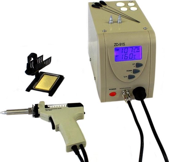
Open your Atari ST, remove the shields, psu and floppy drive so that you only have the mainboard left. Find the YM2149 chip and double check if you have the right chip. Mine was placed under the floppy drive. I recommend to desolder the chip with two persons. one can hold a normal solder iron on the top side pad while the other uses the desolder iron on the bottom side. On this manner the solder will quickly melt and dissapear into the desolder station without leaving solder in the pads. When you finaly got the chip out you can place it into the socket on the YM2149 upgrade board in the same direction as marked on the board (Pin 1 on the right-top corner).
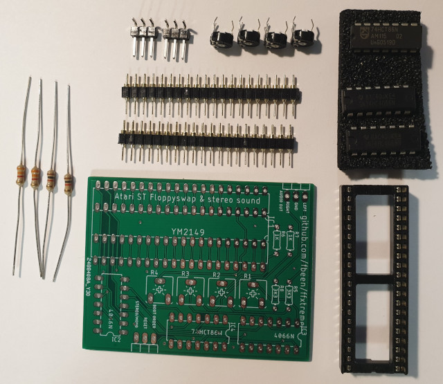
- Place the round header pins in a breadboard, lay the pcb over the pins and solder all pins. Make sure that the pins are straight so that they will fit in your Atari ST mainboard. The pins must be placed at the backside of the pcb!
- Solder the four potentiometers of 2K5 Ohm, 2 normal resistors of 1K Ohm and 2 resistors of 3K3 Ohm on the top of the board
- Solder the three normal resistors of 10K Ohm on the top of the board
- Solder the 74HCT86N (Exclusive OR gates) and the two 4066N (analog switches) in the direction as marked on the pcb.
- Solder the two connectors with three pins each. Use 90 degrees headers or you won't have enough space left later on
- Solder the 40 pin IC socket and place the YM2149 into the socket.
- Solder three Dupont female cables on the 3.5mm audio jack plug (see image) with GND in the middle and plug it on the "audio out" port.

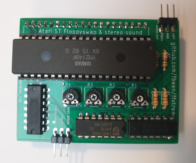
Do not use an IC socket, as the YM2149 upgrade board will be too high to place your floppy drive back! Instead solder the 40 pins into your mainboard keeping the YM2149 in its original direction! Pin 1 on the right-top corner.
Connect three wires to the FlashFloppy upgrade board / STM32F103C8T6:
- Boot Order to C13/BOOT
- Reset to B3/KBDAT
- Stereo/mono to B0/SOUND