soldering PCB
When inserting the connector be careful to level the PCB so the connector sits firmly against the PCB without additional angles. This can be achieved, for example, by using the pin connectors as spacers on the opposite site.

Because the small contacts are too tiny to solder them directly with most soldering irons, it is usually easiest to trust the solder mask to do its job and slowly pull a big blob of solder over the connector. The solder will adhere to the solder pads and avoid the other parts of the PCB, resulting in neat connections. Be aware that the temperature of the soldering iron heavily effect the outcome as the surface tension of the solder depends on the temperature.
If the resistors do not fit the PCB, they can be easily adapted to the different form factor:
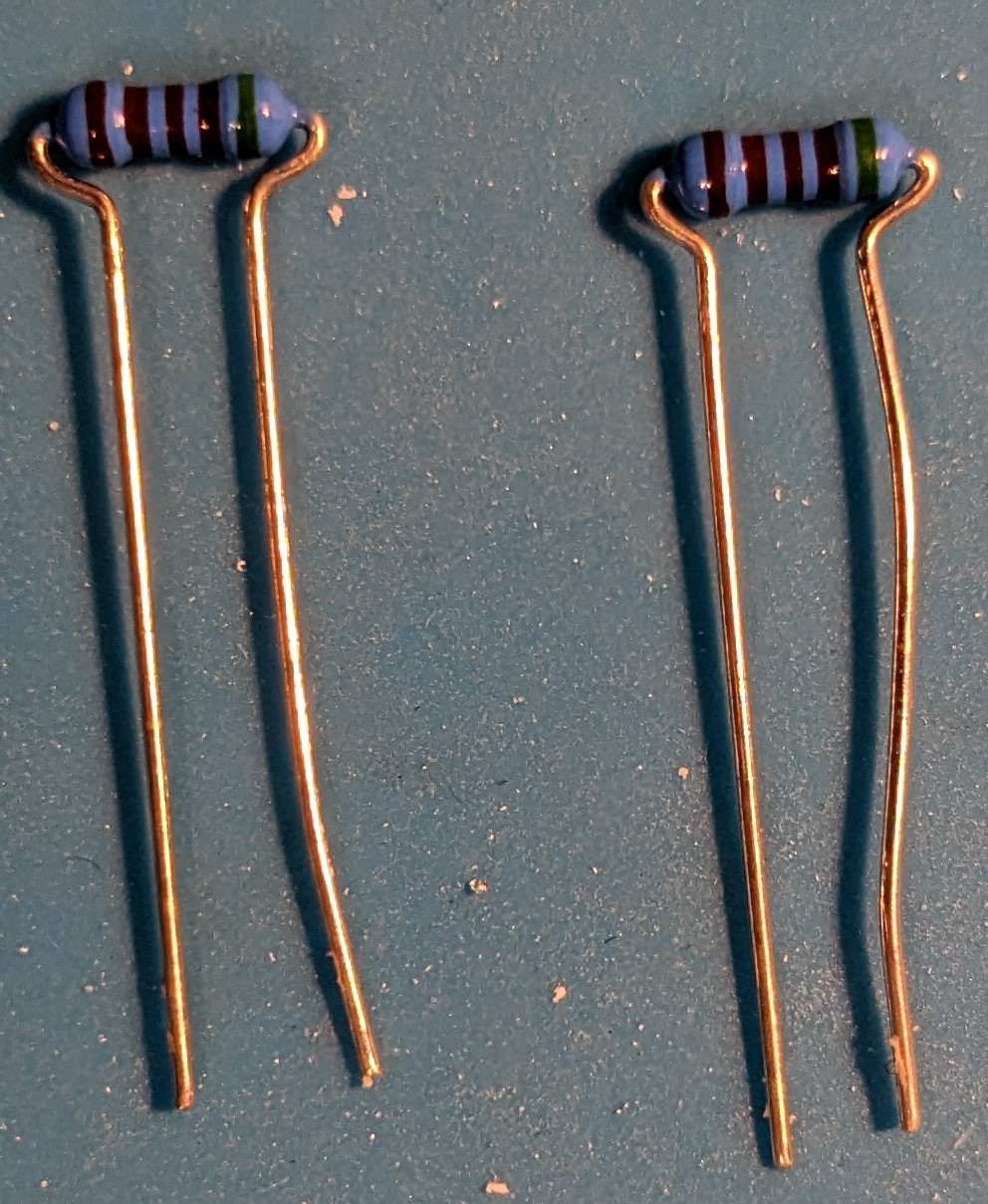
When all parts are soldered, it should look something like this:


However, because the it is easy to miss a contact or to short two neighboring contacts, the connector should be tested by measuring the resistance between several connections.
The contact pads of the servo motors are especially suited to test this, as they can easily be measured against the corresponding pads on the USB connector:


For both the
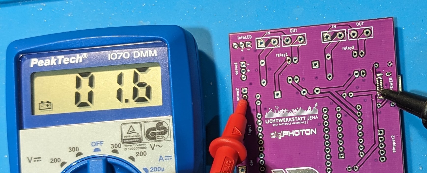
The resistance between the potentials, however, should ideally be

The chosen ESP32 Dev Kit C hast 19 pins per side, while the closest typically available socket connectors has 20. Thus, to solder on the connector, one of the sockets needs to be removed by pulling one of the connector pins from the socket using pliers:


