Staff and User Resources
Where to buy electronic components:
How to Calculate Continuous Current at a Specific Temperature
Upgrade your gray matter: Watch these videos on electronics
MAKE presents: Ohm's Law

MAKE presents: The Resistor

MAKE presents: The Capacitor

MAKE presents: The Multimeter

Collin's Lab: Schematics

Collin's Lab: Breadboards and Perfboards

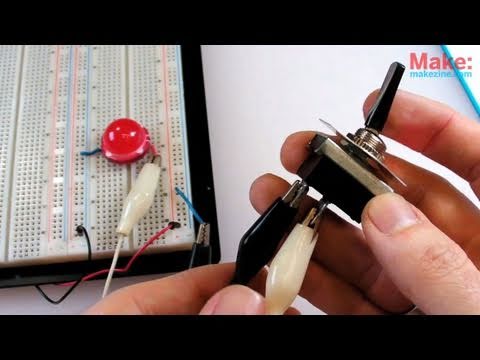
Collin's Lab: Switches
MAKE presents: The LED

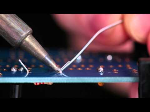
Collin's Lab: Soldering
Circuit Skills: Electronics Enclosures
See Loom Hardware Support for more details.
Sensors
- Accelerometer, 14-bit (MMA8451): Buy, Learn
- OPEnS projects utilizing the sensor: SitkaNet, Slide Sentinel
- Accelerometer, 3-Axis "nano" (LIS3DH)
- Accelerometer/Gyroscope, 3-Axis Analog (MPU6050)
- Accelerometer/Magnetometer, 3-Axis (FXOS8700CQ)
- Accelerometer/Magnetometer/Gyroscope, 3-Axis (FXAS21002)
-
CO2 Sensor, K30 (SE-0018)
- OPEnS sensor profile
- OPEnS project utilizing the sensor: eGreenhouse
- Distance and Gesture Sensor, ZX (SEN-13162)
- Flow Meter, Liquid
- Flow meter, ultrasonic (TUF-2000M-TS-2): Buy, Learn
- OPEnS project utilizing the sensor: FloDar
-
GNSS Receiver, Swift Piksi Multi
- OPEnS project utilizing the sensor: Slide Sentinel
-
Humidity & Temperature sensor (SHT31-DIS)
- OPEnS project utilizing the sensor: eGreenhouse
- Humidity & Temperature Sensor, Mesh-protected Weather-proof (SHT-30): Buy, Learn
- OPEnS projects utilizing the sensor: Dendrometer, RainSavor, SitkaNet
-
Magnetic sensor, Linear (AS5311)
- OPEnS projects utilizing the sensor: Dendrometer
- Load Cell Amplifier (HX711)
- Luminosity/Lux/Light Sensor, High Dynamic Range Digital (TSL2591): Buy, Learn
- OPEnS project utilizing the sensor: eGreenhouse
- Luminosity/Lux/Light Sensor (TSL2561)
- NIR Sensor (AS7263)
- PH Sensor, DFRobot
- Pressure Sensor (0.15 PSI ~ 18.85 PSI) (MS5803-01BA)
-
Pressure Sensor (4.35 PSI ~ 15.95 PSI) (MS5803-02BA)
- OPEnS projects utilizing the sensor: eDNA sampler, SitkaNet, Smart Rock
- Pressure Sensor (0 PSI ~ 30 PSI gauged) Honeywell ABPDANT030PG0D3
- OPEnS sensor profile
- OPEnS projects utilizing the sensor: eDNA sampler
-
RFID Reader, Simultaneous - M6E Nano (SEN-14066)
- OPEnS projects utilizing the sensor: RFID Soil Moisture
- Soil Moisture Sensor, Decagon 5TM (5TM)
- Soil Moisture Sensor, Decagon GS3 (GS3)
-
Soil Moisture Sensor, METER Group Teros 11
- OPEnS project utilizing the sensor: SitkaNet
- Soil Moisture Sensor (SEN-13322)
-
Spectroscopy Sensor, Triad (AS7265x)
- OPEnS projects utilizing the sensor: Weed Warden
- Thermocouple Type-K Glass Braid Insulated Stainless Steel Tip: Buy, with MAX31855 amplifier: Buy, Learn
- OPEnS project utilizing the sensor: FloDar
- Thermocouple Amplifier, Universal (MAX31856)
- Thermopile Sensor, Contact-less Infrared (TMP007)
- Turbidity Sensor, DFRobot : Buy, Learn
- OPEnS projects utilizing the sensor: FloDar, Smart Rock
- Ultrasonic Sensor Component Module, Industrial Indoor (MB1232)
- Visible Sensor (AS7262)
Actuators
Communication
- SparkFun 4G LTE
- Feather 32u4: LoRa, 2G FONA, Bluetooth
-
Feather M0
-
WiFi
- OPEnS project utilizing the platform: eDNA sampler
- LoRa: RFM95 900MHz
- OPEnS project utilizing the platform: SitkaNet
- Bluetooth
-
WiFi
-
FeatherWing: Ethernet
- OPEnS project utilizing the platform: SitkaNet
- FiPy: WiFi, Bluetooth, LoRa, Sigfox and dual LTE-M (CAT M1 and NBIoT)
-
RockBlock MK2: Satellite
- OPEnS project utilizing the platform: Slide Sentinel
You will need to either 1) Create your own 3D model and export to a .stl file (see below) or 2) Find the model you need on Thingiverse or a similar website, download and export to a .stl file. All prints must be scheduled in advance and usage reported via our website.
See here for another guide.
Videos on 3D printing
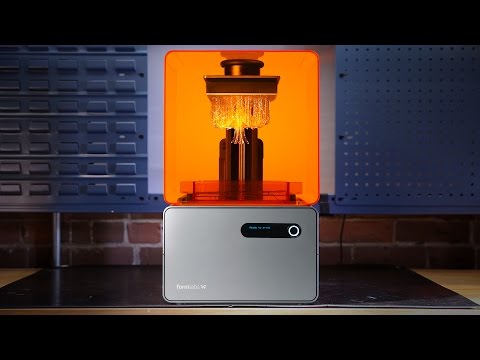
Introduction to Stereolithography from FormLabs
What if 3D printing was 100x faster? TED Talk by Joseph DeSimone

Software
Autodesk Fusion 360
Start by making a free student account here. Download the Fusion360 application. Start with these YouTube tutorials and watch Lessons 1-8 here to learn how files work in the program:. And watch this 3D printing specific tutorial for Fusion360 to output your design as .stl files. Pros:
- Industry-standard software platform
- Free educational account
- Nice interface
- Realistic 3D renderings with many different material skins and backgrounds (just for looks really) Cons:
- Not as easy or intuitive to share and modify parameters of designs with others
- Can be expensive to maintain license when you graduate
Using a Slicer
A Slicer is a program that translates a 3D Model into instructions for a printer (sliced into 2D layers) based on a group of settings. There are several slicers, each with slight variations in their settings, but we use Lulzbot's edition of Cura for the TAZ printer, Simplify3D for the Fusion3 F400-S, and Prusa's edition of Slic3r for the Prusa i3 MK3S. For each program, you will want to export the file as gcode to the respective printer's SD card.
Design Tips
- Use overhangs conservatively. If possible, angle them by 45+ degrees.
- Keep it as simple as possible. Limit your use of complicated features such as bridges or patterns.
- Most printers will be unreliable for features smaller than 1mm. Where possible, thicken walls and increase the size of small features. If not, think of ways to perform the same function with a larger feature elsewhere in the design.
- Make sure at least one outer face is large and flat. This will be the base of the print that will adhere to the bed of the printer. An angled face will not work very well.
- The mesh or surface of the 3D model must be watertight and a solid. More technically, all faces of the object must construct one or more closed volume entities. When the faces are not fully closed, they produce gaps or holes in the model and those holes and gaps will keep the model from printing correctly.
- Your model does not need to be manually hollowed out.
- If possible, build your model in millimeters, or convert to mm when you get ready to print your file.
- Make sure you delete any 2D elements from your model that were used to create sweeps, lofts or other complex shapes. If these elements remain in your file, they can cause naked edge problems. Remove them as you go and it will be easier to have a clean print. Remember that your model has to be a SOLID watertight object. It cannot contain 2D planes, lines or other elements that can exist in the native modeling format. 2D objects cannot be printed, even if assembled into a "box" or another solid-looking volume. The pieces must be welded together and solid forms created to be printed.
- Before scheduling your first job, come by our lab to do a geometry check. Model designs containing holes and gaps adversely affect the quality of the printed model. Third-party software for this purpose attempts to fix the geometry of problematic files. Many companies that provide 3D printing services have a file upload that you can use to check to see if your file is OK before submitting. Another good tool to use is a product called NetFabb. They have a free version (netfabb Basic) that you can download, as well as a pay version, that will help you analyze problems with your STL file. They also provide a cloud service that can check your files. For help using NetFabb, see a Shapeways tutorial. MeshLab is another program that you can use to analyze your files.
- If your model is made up of multiple parts, export each part as a separate STL file. The parts can be laid out in the machine in different orientations that will optimize the print for both cost and print time.
- Use your software’s help files and the vendor’s websites to search for information on 3D printing. Rhino provides a link to help with 3D rendering.
- There are sites that help with the commands needed to correct many problems with a model: Rhino has a page on checking/repairing meshes.
- It may be necessary to convert your solid to a mesh. Please see your software for steps on how to accomplish this.
-
Things to be careful of:
- degenerate faces - Mesh faces that have 0 area
- zero-length edges - Edges with no length, created by degenerate faces
- nonmanifold edges - Faces that have more than one face connected to a single edge
- naked edges - A surface or polysurface edge that is not connected to another edge
- duplicate faces - Identical faces in a single mesh
- faces that could make it better if their directions were flipped? The faces in a mesh object should point in a consistent direction
- disjoint pieces - Mesh objects that do not connect but are considered a single mesh
Material selection
- Filament guide from MatterHackers
- Filament comparison from Rigid.ink
- Explanation of resin properties from Liqcreate
- Resin library from Formlabs
Printing in the OPEnS Lab
- Print area and tolerances: Vary by printer, refer to the specifications on the OPEnS Equipment Page
- Required print file type: Stereolithography file, with an STL extension (.stl). Most CAD programs can save or export in this format, as can other free 3D modeling software packages, such as Sketchup Make, AutoCAD's 123D, TinkerCAD and Blender.
- Cost: The cost for 3D printing in the OPEnS Lab is determined by the amount of filament (including support material), type of filament, and printer used for your model. Billing will be conducted through ONID and will show up as a 3D printing charge on your account. Prices are available on the Equipment webpage.
- Access: See Lab Access page for OPEnS 3D printing etiquette
-
Starting the print for all printers:
- Scan the QR code for logging your print, and fill out the form completely.
- Check the filament spool (or resin reservoir) currently loaded in the printer. Consider the weight of your part (as given by the slicer program) and know that each spool starts with 1KG of material. If it appears to not have enough plastic or you are unsure, ask a lab technician for assistance.
- Prepare the print bed per each machine's guidance.
- Check the printer for loose materials accidentally set on or next to the print bed or any moving part. The print bed should not have plastic adhered to it.
Printing with Ender Farm
- Open CURA software on the computer in the farm.
- Click on the LOAD MODEL icon and locate the .stl file you wish to print
- The design should appear immediately after loading (sometimes it might be very very tiny, but it's there and you'll scale it in following steps).
- Chose print quality. Go to File > Open > Profile > Documents > 3DPrinter > PrintProfiles.
- In the PrintProfiles folder, you can choose Fast, Standard, or High-quality settings.
- You will likely need to re-orient or scale your object. Do this by using the ROTATE, SCALE, and/or MIRROR icons at the bottom of the screen. Keep in mind some orientations are better than others, consult with the OPEnS technicians your first time, or if you have questions.
- Remove the SD card from the Taz Lulzbot and insert it into the computer
- Export your gcode file to the SD card, safely eject, and re-insert into printer slot.
- Move the print head out of the way. Use either ABS paste or hairspray to evenly coat the print surface. Do not get adhesive on any other part of the printer. If you do, let an OPEnS technician know so they can clean it before the remaining steps.
- On the printer, click on CONTROL. Set the nozzle to appropriate temperature according to the material being used.
- ABS settings: Extruder 240⁰C, Bed 110⁰C, Removal 50⁰C
- PLA settings: Extruder 205⁰C, Bed 60⁰C, Removal 45⁰C
- NYLON 645 settings: Extruder 242⁰C, Bed 30⁰C, Removal 60⁰C
- Set bed to appropriate temperature according to the material used.
- Select your file in the interface.
- Click Print.
- Monitor your print closely for at least the first 2 layers before cleaning up and leaving your space.
Printing with Prusa i3 MK3S
- Open Slic3r software.
- Click on the LOAD MODEL icon and select the .stl file you wish to print.
- You will likely need to re-orient or scale your object. Do this by using the ROTATE, SCALE, and/or MIRROR icons at the bottom of the screen. Keep in mind some orientations are better than others, consult with the OPEnS technicians your first time, or if you have questions.
- Select the Print Settings you would like to use in the drop-down menu on the right side of the screen. 0.15mm QUALITY MK3 is a good general-purpose setting.
- Select the type of filament you are using. Make sure the right filament is loaded into the printer and it is sufficient for your print.
- Click the Slice Now button and save the .gcode file to the SD card for the printer.
- Insert the SD card into the slot in the printer.
- Do not use any adhesives on the Prusa bed.
- Push the knob on the printer when on the main info screen and select the Print from SD option. Select the file you wish to print.
- Monitor your print closely for at least the first 2 layers before cleaning up and leaving your space.
Printing with Fusion 3 F400-S
- Simplify3D has a great starter guide located here.
- After exporting your gcode to the SD card, safely eject the card from the computer and then place it back into the Fusion3 F400 immediately.
- Move the print head out of the way. Use either ABS paste or hairspray to evenly coat the print surface. Do not get adhesive on any other part of the printer. If you do, let an OPEnS technician know so they can clean it before the remaining steps.
- Turn on the printer and wait for it to start up. If the printer was already on before inserting the SD card, press the orange reset button or cycle power and wait for it to reboot.
- Using the printer's control panel, locate your file. Select it and start the print.
- The printer will begin a heatup cycle; this should take several minutes. You are required to stay until the first layer is done printing. If the plastic is not adhering to the bed or if something goes wrong, stop the print and talk to a lab technician.
Additional Resources
Printing with Form 2
Printing with Anycubic
- Acquire the materials you want to cut. See a list of approved materials from ATXHackerspace. Also, purchase a sheet or two of cardboard to cut a test design to prove it will work on your desired material.
- Materials must have original labels and be approved by OPEnS technicians before use
- Schedule a cut time on our OPEnS portal
- Show up at your scheduled time with labeled materials and your design as a .DXF file
- Eye protection and other safety gear as appropriate shall be worn during laser operation
- Trained OPEnS technicians alone are authorized to operate the laser cutter
- Laser cutter use must be reported through our Google Form.
Show More
- Clean five reflectors and focus lens prior to each use (use Kimwipes and 99% isopropyl alcohol)
- Clean the cutting chamber to ensure it is free of dust prior to each use
- Clean water tank and change circulating water weekly. Use purified water.
- Clean guard rail every 2 weeks.
- Clean exhaust fan as needed.
Show More
- No bubble in water laser tube
- All electrical wire terminals intact
- Pull laser head to check smooth movement
- Move crossbeam front and back to confirm noise free
Show More
- Exhaust fan is not noisy (indicates it is dirty)
- No excursion in light path (all reflectors are lined up appropriately)
- Press direction key to test normal movement of laser head
Show More
Show More
Show More
The T-962A re-flow oven is the cheapest way to obtain a re-flow oven for delicate surface mount soldering jobs. By adding solder paste to the pads, manually or stenciling, it can be very easy to place and solder components like surface mount logic chips. The oven is not perfect, so modifications were made to bring it up to functionally. It also includes a tool for stenciling, which spreads the solder paste over it. The oven's use should be considered for projects where soldering by hand is too tedious or nearly impossible. Prior to use, verify via specification sheet that all your components can safely withstand the temperature curve being utilized - see manual for how to display the soldering temperature and duration for each curve.
An alternative method of reflowing is by using a toaster oven. It is less accurate than the T962 oven, but it is much cheaper. Depending on the size and heat distribution, a toaster oven may be able to reflow multiple boards at the same time. Documentation for using the oven can be found here.
Show More
The re-flow oven can be used for speedy soldering jobs or it can be used to placing delicate components which may require stenciling.
The T962 oven series of ovens are cheaply produced re-flow ovens so they can be bought in the range of hundreds of dollars rather than several thousand. However, the reason they are much cheaper than standard re-flow ovens is that physical, circuitry, and firmware updates may be needed dependent upon the specific oven model. More about oven models can be found in from Unified Engineering though more variations may exist.
Show More
A re-flow oven is designed to run for about 7 minutes with its heat up time and cool down time critical to the quality of the jobs they do on the PCB. Due to the fact the oven needed modifications to be used, the following procedure is recommended:
- Be aware of what is going to be on the board. If plastic or temperature sensitive (e.g. TE MS5803 pressure sensor) components are going to be placed on the board, attach them AFTER using the oven.
- Use lead-free (e.g. Sn42/Bi57/Ag1) low temperature (melting point ~138°C) solder paste (e.g. MG Chemicals 4902P-15G ). Note that solder paste should be refrigerated for longest shelf life.
- Solder Paste and Stenciling is a good guide to get started with stenciling.
- Remember that stenciling may take a few attempts, so if you need to retry simply clean the stencil with rubbing alcohol (as long as this is safe for components). Do not let the rubbing alcohol stay on for too long.
- Pick a curve appropriate to the solder paste melting point temperature and maximum temperature/time for soldering of components. For the OPEnS Lab oven, Curve #5, with a maximum temperature of 160°C, is recommended.
- Place two PCB's on below the PCB being used and place them so they allow maximum airflow below and above the PCB of interest.
- Stay within sight of the oven when using it.
- When it is finished, be very careful when removing the PCB as it may be hot. Try using a tool to remove the PCB.
Show More
* Be aware of the temperature sensitivity of what is already on the board and what is being soldered onto the board: 1) if there are plastic components soldered on the PCB, then it may not be advisable to use the oven as they may melt and produce fumes; 2) electronic components may have lower heat tolerances than the maximum temperature of the oven for the chosen curve. * Do not use the oven repeatedly as it will take time to cool down; allow for 2-3 minutes between each use. * Be aware the oven does not contain all of the heat, so the surrounding area will be very hot as well so be careful not to touch or put things around the oven in use.
Encasing sensors in potting compound helps increase their durability by protecting them from physical damage and water intrusion/corrosion.
Show More
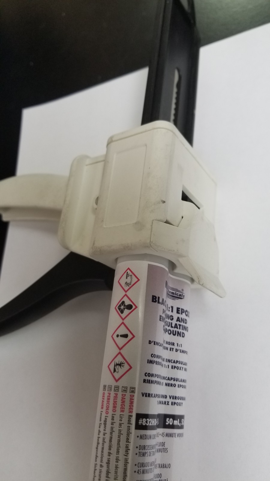
* Potting Compound- MG Chemical 832HD * Dispensing Gun- MG Chemical 8DG-50-1-1 * Mixing Nozzle- MG Chemical 8MT-50 * Mold
Show More
The simplest design for a mold is a single piece with an open top. This minimizes the chance of a leak and is easy to 3D print without supports. Here are a couple of examples.
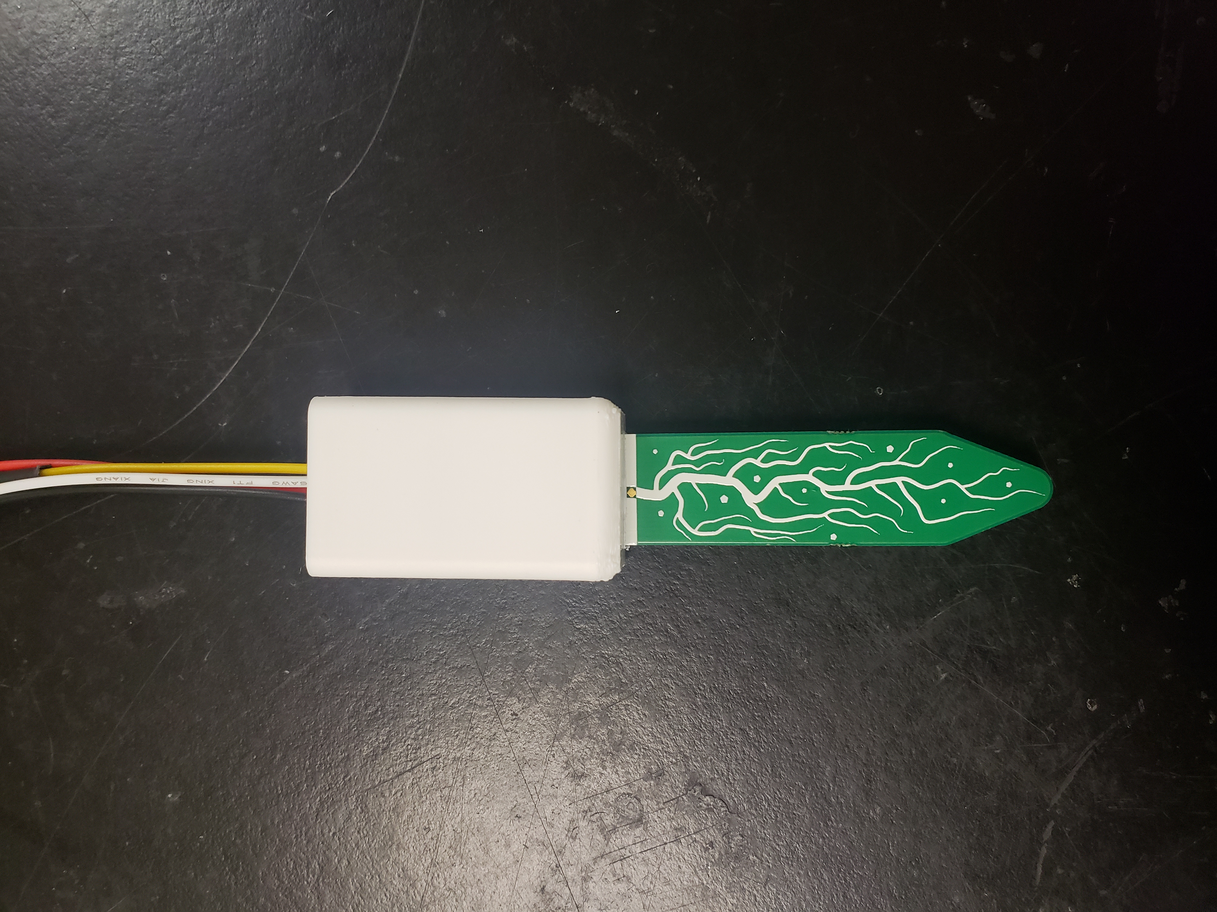
Adafruit Capacitive Soil Moisture Sensor


MS5803 Pressure Sensor


The mold design must allow the potting compound to completely cover any exposed electronics without interfering with the sensing elements/areas of the sensor. Part of the wires leading to the sensor should also be covered by the potting compound. This provides some strain relief to the solder pads and ensures the wire won’t break at the connection point to the sensor. The mold must also be watertight so the potting compound doesn’t leak. Super glue can be used on the outside of the molds to seal the mold.
Show More
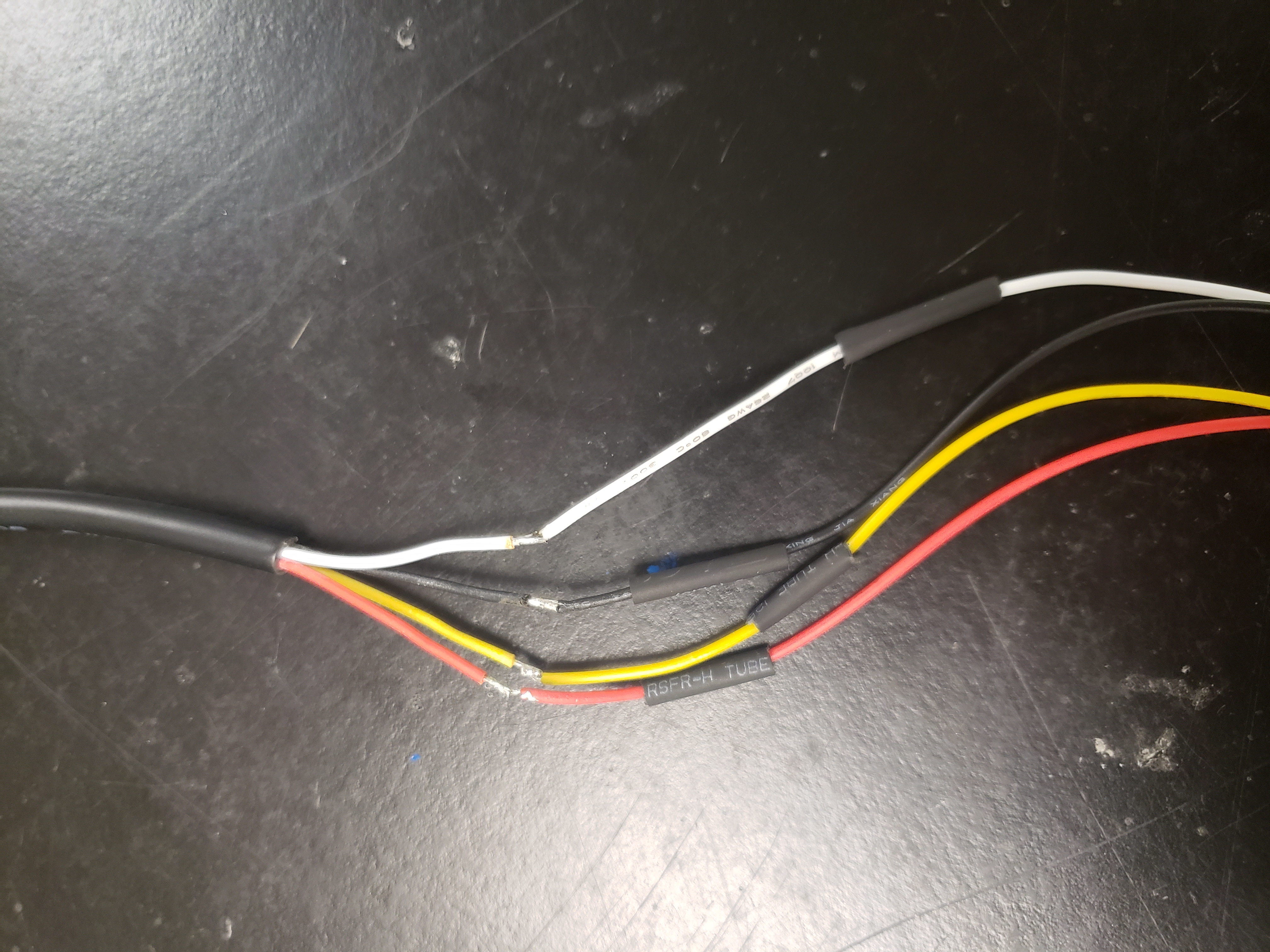
- Connect the wires to the STEMMA Sensor, then solder and heatshrink the wires to the male threaded connector.
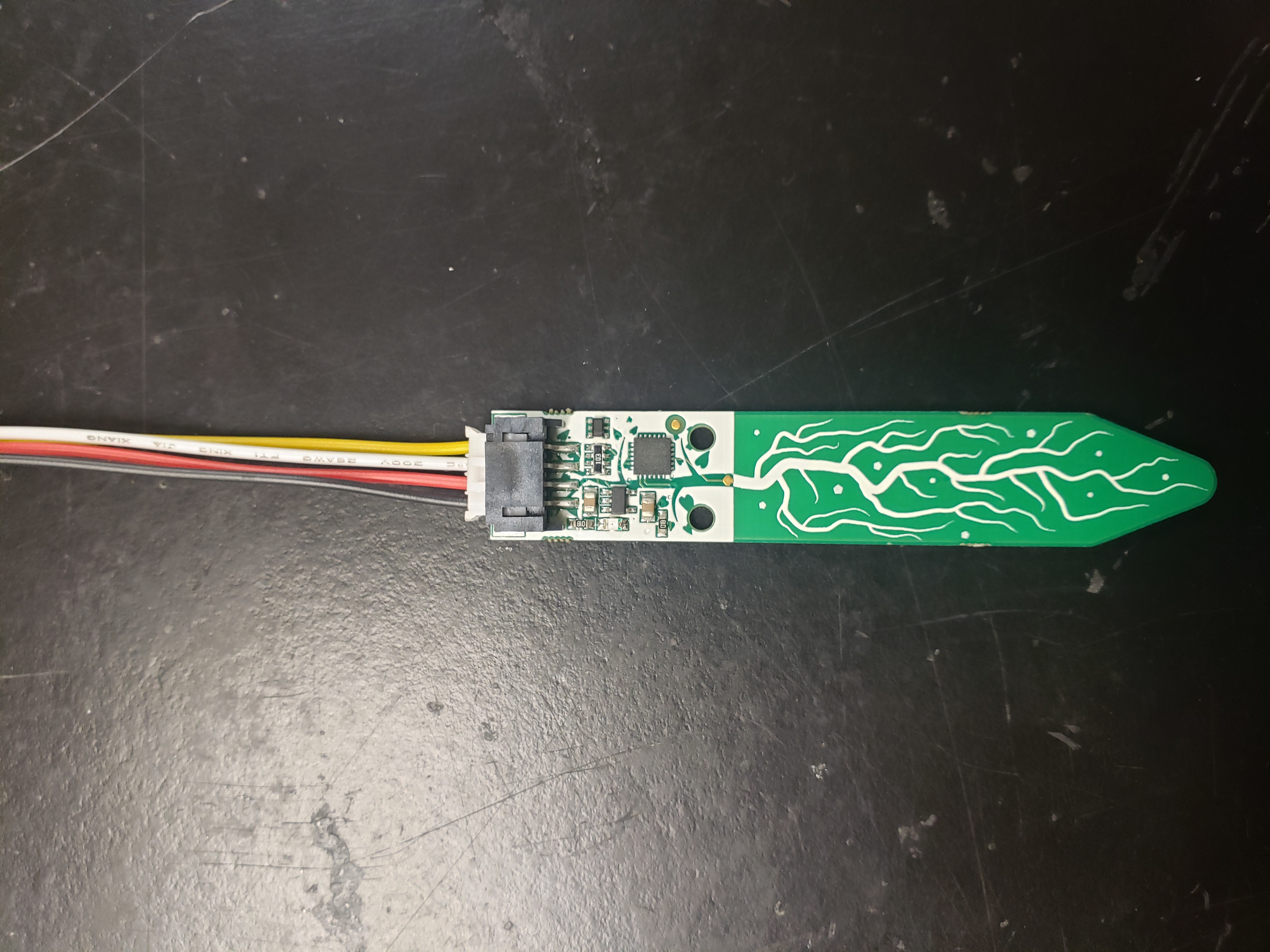
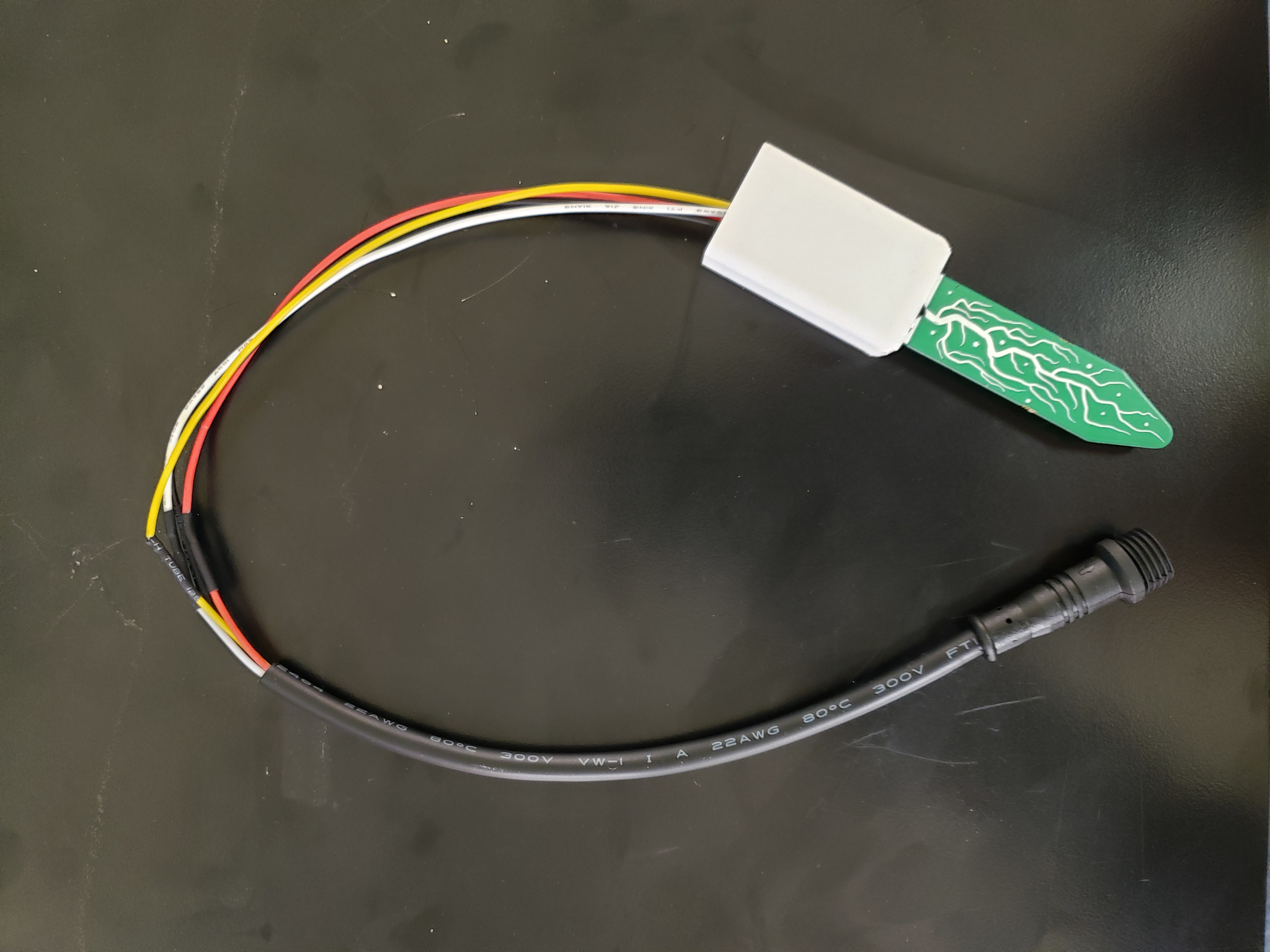
- Push the STEMMA sensor through the slot in the plastic mold until the gold dot is completely visible.
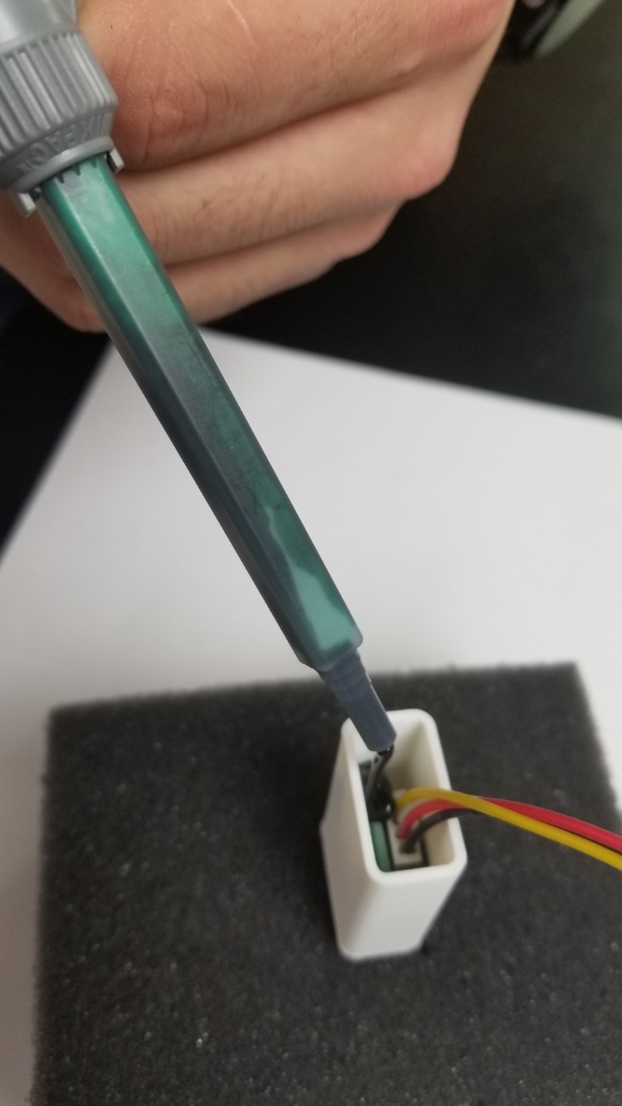
Potting Compound, Dispensing Gun, and Mixing Nozzle:
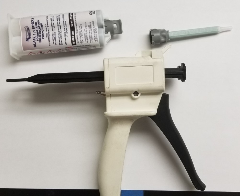
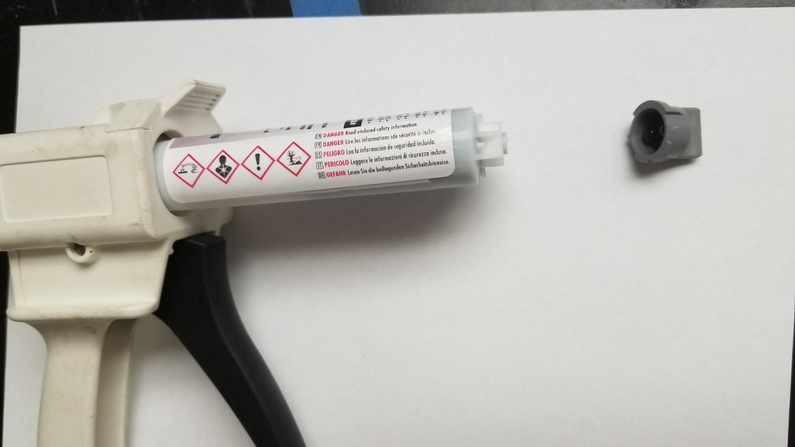
- Place the potting compound cartridge into the dispensing gun.
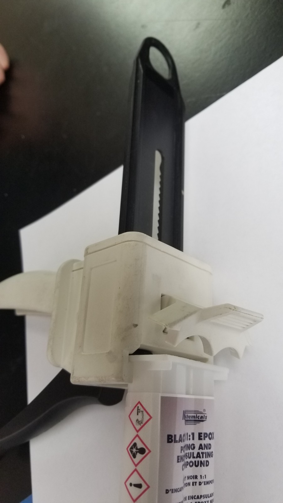
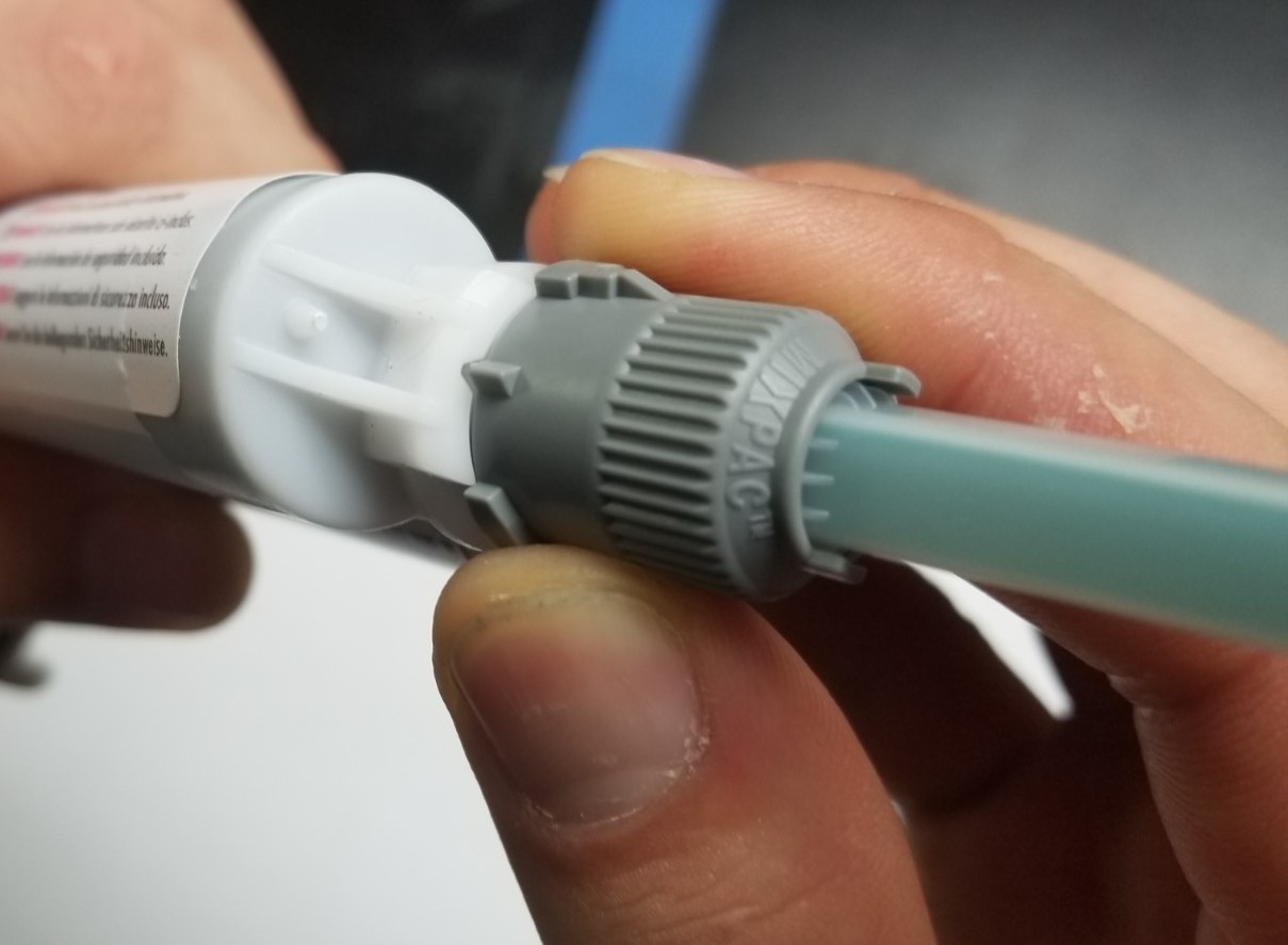
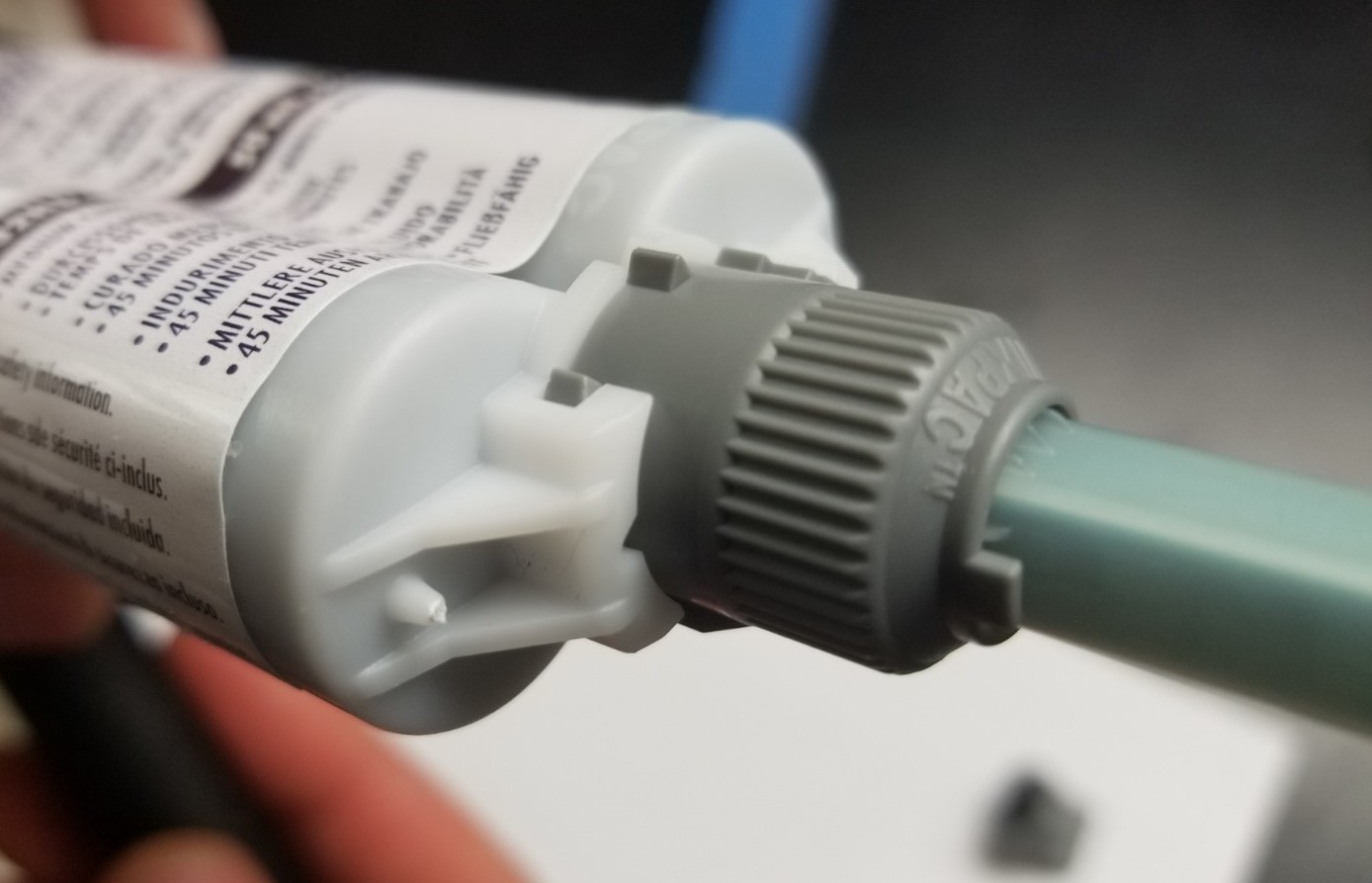
- Uncap the cartridge. To attach the nozzle, align the notch, push the nozzle onto the cartridge, and turn the grey connector 90 degrees clockwise.
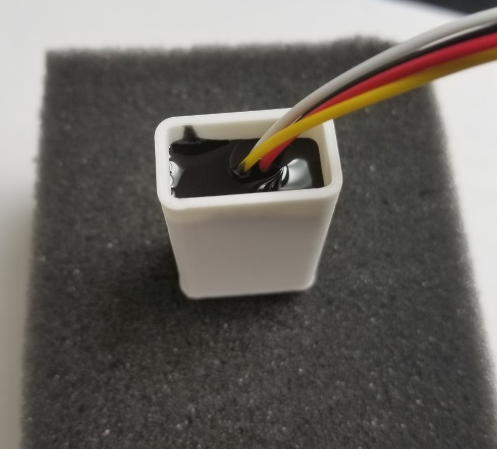
- Place the STEMMA sensor in foam to keep it upright during the potting process.
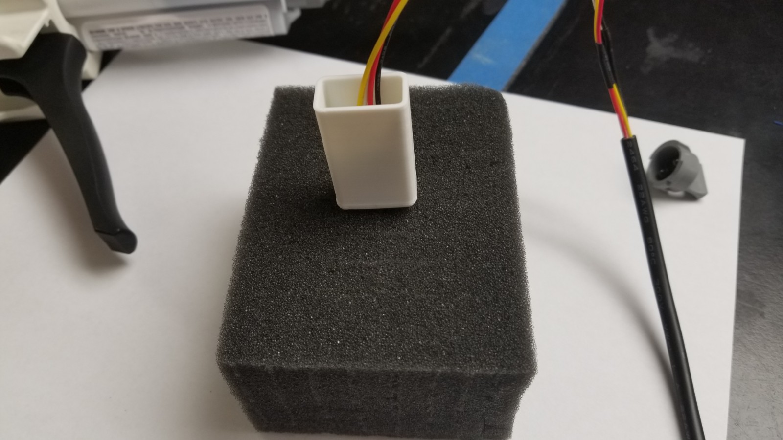
- Squeeze the handle of the dispensing gun and fill up the mold until the PCB is completely covered. Leave the sensor undisturbed to 24 hours to cure.