This project aims to revive the PDP-6 (and later PDP-10) computers by DEC.
I started by writing a very low level emulator in C based on the schematics. Later I also wrote an accurate verilog simulation that also works on an FPGA.
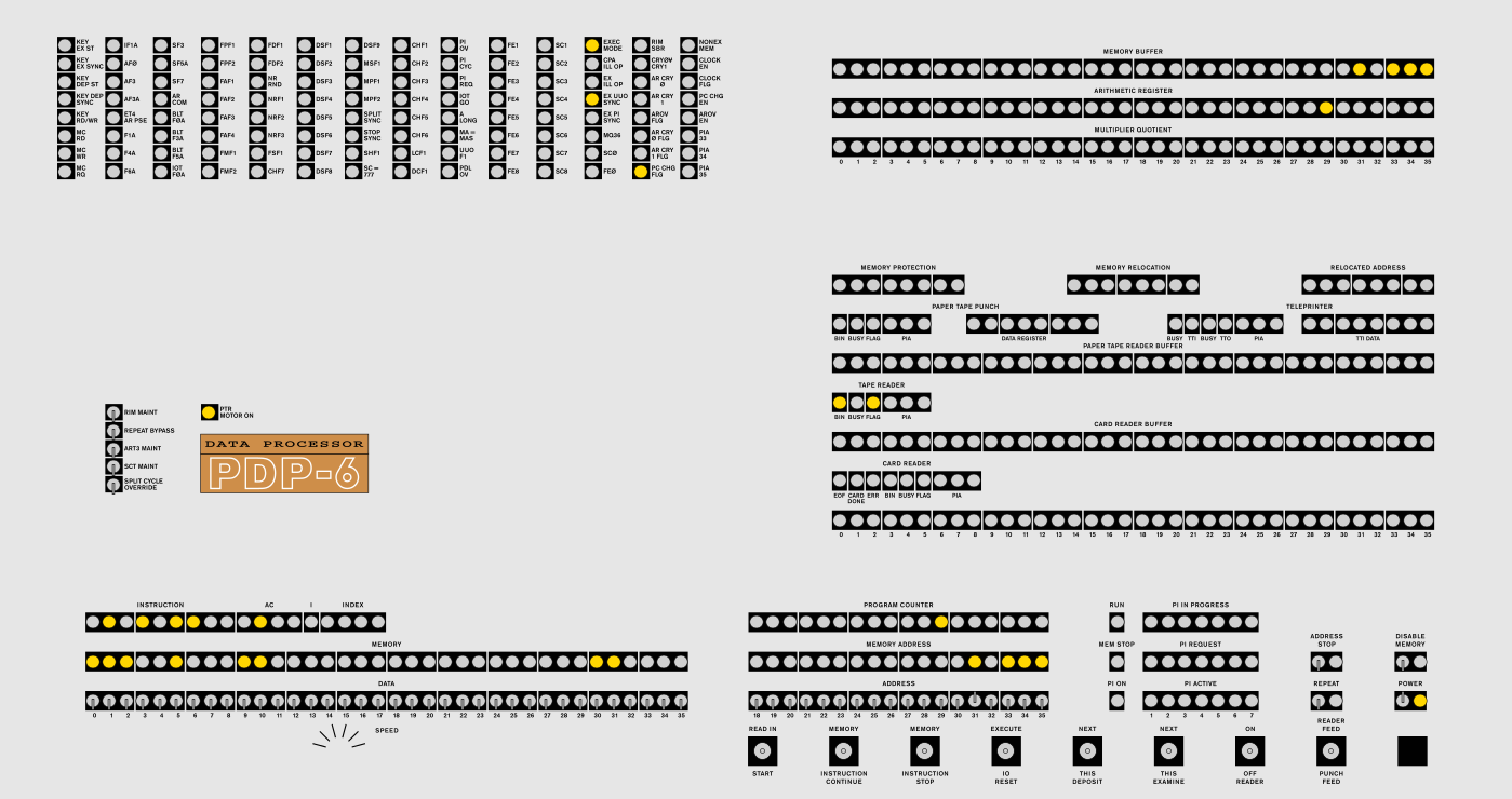
Both are driven by a virtual front panel but the plan is to create a replica of the original panel.
The maintenance manual has flow charts, schematics and explanations: Volume1 Volume2
The code is more or less a transcription of the schematics into C.
This means you will not understand it unless you're familiar with the maintenance manual.
Pulses are represented as functions, when a pulse triggers another pulse
it does so by the nextpulse function which adds a pulse to the list of next pulses.
In the main cpu loop the list of current pulses is iterated and each pulse is called,
then (after checking some external signals) the current and next pulse lists are swapped
and the process begins anew.
The timing was not accurately modeled and there is room for improvement.
Due to the inexact timing the hardware connections (through the memory and IO bus)
were not implemented too accurately. This may change in the future.
The supplied makefile assumes gcc (there are flags to silence some stupid warnings). Otherwise you need SDL and pthread.
The cpu (apr), console tty and paper tape/punch are implemented. There are no other external devices yet. The only things missing from the cpu is the repeat key mechanism.
The verilog code is a very accurate transcription of the schematics as well. Since the real machine is asynchronous I had to pull some tricks to make it work on an FPGA. The real machine uses delays that are triggered by pulses and output another pulse after some time. Instead of pulses I use clock enables, and delays are implemented by a counter synchronized to the 100MHz system clock.
My FPGA board is a Terasic Cyclone V GX Starter Kit. Communication with the virtual front panel is done over I²C via GPIO pins 2 (SCL) and 3 (SDA). The board's SRAM can also be read and written over I²C. The TTY is connected to UART over GPIO pins 4 (RX) and 5 (TX)
emusource for the emulatorverilogsource for the verilog simulationarteverything graphicalcodesome test code for the PDP-6panel6virtual panel for the FPGAtoolstools like an assembler and linkermiscsome misc. and old stuff
- repeat and maint. switches
- test thoroughly!
- devices
- timing