Calibration Explained
The full run, in the order that actually matters. Do it top to bottom and stop when your prints look the way you want — you don't need every step.
Golden rule: change one thing, then print a test. If you tweak five settings and the next print is worse, you won't know which one did it.
Calibrate from the machine outward — mechanical first, then the first layer, then motion quality, then slicer. Doing it out of order means redoing work.
| Step | Fixes |
|---|---|
| 0. Touch calibration | Tap targets are off on a fresh install |
| 1. Mechanics | Loose hardware that no software can fix |
| 2. Temperature (PID) | Inconsistent extrusion from wobbly heater temps |
| 3. Axis Twist | First layer uneven left-to-right |
| 4. Z-Offset & Bed Mesh | First layer height everywhere (bed mesh + Z-offset, one guided flow) |
| 5. Input shaper | Ghosting/ringing on fast prints |
| 6. E-Steps Calibration | Prints uniformly over- or under-extruded |
| 7. Pressure advance, flow, temp | Corner bulges, stringing, over/under-extrusion |
| 8. Skew correction | Parts that aren't square |
| 9. TMC Autotune | Loud or hot motors (optional) |
The screen's Tune → Calibration menu numbers steps 3–9 the same way, in the same order, in its own list (labelled 1–6 there since it only lists steps with a dedicated calibration screen — mechanics, PID, and pressure advance/flow are done elsewhere, so they don't get a row).
"Which one fixes my problem?"
| What you see | Most likely fix |
|---|---|
| Tap targets off / need to press slightly away from what you mean | Step 0 — touch calibration |
| First layer uneven left↔right, bed mesh didn't help | Step 3 — Axis Twist |
| First layer uneven all over / patchy adhesion, or too high/low everywhere | Step 4 — Z-Offset & Bed Mesh |
| Ghosting/echoes after sharp corners | Step 5 — Input shaper |
| Prints look uniformly too thin or over-full, not just at corners | Step 6 — E-Steps |
| Bulging corners, blobs, gaps | Step 7 — Pressure advance + flow |
| Parts not square / parallelogram | Step 8 — Skew correction |
| Loud or hot motors | Step 9 — TMC Autotune |
| Layer shift right after pause/resume | See Troubleshooting |
A fresh install has no touch calibration data, so taps are uncompensated raw coordinates. Run the 9-tap wizard once and the touchscreen becomes accurate.
Screen: Settings → System → Reset Touch Calibration
The screen shows three crosshairs in turn — tap the centre of each three times (lift your finger between taps; the screen averages the three for accuracy). Takes about 30 seconds. The calibration is saved automatically and survives reboots.
Redo this any time tap targets feel noticeably off, or if you change
display_rotate— the calibration coefficients are rotation-specific.
Software can't fix loose hardware — it can only paper over it.
- Belts: firm. A plucked belt should "thunk", not flap, and both sides should sound about the same pitch — a noticeably lower/duller thunk on one side usually means that belt is looser. Slack belts cause layer shift and ringing.
- Gantry: square. The X bar should be parallel to the bed, not tilted.
-
Bed level (rough, by hand): if your bed screws are wildly uneven, the BLTouch probe and bed mesh
can usually compensate — but a bed that's very far off makes the mesh work harder than it needs to,
and in bad cases can exceed what meshing can fix. If you installed the optional Screws Tilt Adjust
mod (offered at install time), run
SCREWS_TILT_CALCULATEfrom the Klipper console — it tells you exactly which corner screw to turn and which way, instead of guessing. - Bed: not rocking. Gently push each corner — no play.
- V-wheels/rails: snug but not binding. Should spin with light finger pressure.
- Nozzle: clean, no plastic blob.
Done when: nothing wobbles when you nudge it. Five minutes here saves hours later.
Wobbling hotend or bed temperature = inconsistent extrusion. If your temp graph swings more than ~±1 °C at target, PID-tune. In the Klipper console (Mainsail or the Console tab on screen):
PID_CALIBRATE HEATER=extruder TARGET=230
PID_CALIBRATE HEATER=heater_bed TARGET=60
SAVE_CONFIG
If you installed the Creality macros, PID_HOTEND / PID_BED do the same.
Done when: the temperature holds flat at target on the graph (< ±1 °C).
Skip this if your first layer is consistently even from left to right. Do it if you see the classic KE symptom: first layer is fine in the middle but squished on one side and lifting on the other — and bed mesh hasn't fixed it.
Full guide with instructions: Axis Twist Compensation
In short: Tune → Axis Twist on the screen runs a 5-point guided paper test across the X axis. The result corrects the probe readings so the bed mesh is accurate. Takes ~15 minutes, done once.
This is 80% of whether prints "look good." Tune → Calibration → Z-Offset & Bed Mesh on the screen walks you through both halves in one guided flow — the recommended path, especially right after changing hardware (bed, nozzle, BLTouch remount):
- Z-offset paper test — the wizard homes fresh and runs the same manual paper-drag probe as the standalone Z-offset tool: jog down in small steps until you feel light drag on a sheet of paper, then Accept.
- Bed mesh — runs automatically right after, no input needed. Maps the bed's hills and valleys so Z follows them everywhere, not just the centre.
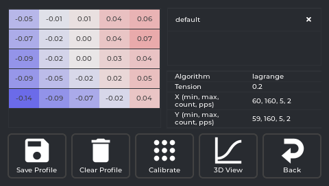
- Review, then save — both new values are shown together before anything is written. From here you can Save & Restart directly, or optionally try Refine with Load Sensor first (see below).
If you installed adaptive meshing (the installer default), your slicer's ADAPTIVE_BED_MESH_CALIBRATE
start G-code still re-meshes just the print footprint at the start of every print, on top of whatever
full mesh the wizard saves — see Adaptive Meshing.
Prefer doing it by hand, or don't want the guided flow? Both halves are still available as separate
tools: BED_MESH_CALIBRATE from the console or Tune → Bed Mesh → Calibrate on the screen, and the
live baby-step readout on the print-status screen or Tune → Z Offset (0.01–0.05 mm nudges: lines not
fusing/gaps = too high, lines translucent/flat = too low, squished and fused with no gaps = correct).
What about the strain-sensor auto Z-offset? The KE's nozzle load sensor can also propose a Z-offset value. Its repeatability has measured very differently across sessions — an ~83 µm/32 µm stddev spread one time, a tight ~21 µm spread another — so treat any single number as printer- and session-dependent, not a fixed spec. That's exactly why the wizard treats it as an optional "Refine with Load Sensor" step after the paper test, never a replacement for it: it shows both values side by side and always makes you pick — it's never auto-applied. It also self-saves internally every time it runs, so the wizard snapshots your config first and can fully discard the sensor attempt if you'd rather keep the paper-test value.
Done when: the first layer is uniform with no gaps, and it stays that way print after print.
Those faint echoes trailing sharp corners are vibration. Input shaping cancels them.
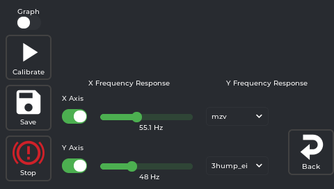
On the screen: Tune → Input Shaper. There's a switch per axis (X, Y) — leave both on to test both at once, or switch one off to redo just the other. There's also a Graph switch, off by default; turn it on first if you want an actual plotted curve rather than just the numeric result.
- Tap Calibrate — the printer shakes through a frequency sweep (~1 minute) on whichever axis switches are on.
- Each tested axis gets an updated frequency value and a recommended shaper type in its dropdown (with the plotted graph too, if you turned Graph on). You can change the dropdown yourself if you want to try a different shaper.
- Tap Save.
- If you only tested one axis, flip the switches (this axis off, the other on) and repeat — remember to move the accelerometer to the bed for the Y measurement, since the sensor must be on whatever moves for that axis.
The Stop button on this panel is a general emergency stop, not a "cancel this test" button.
Done when: a fast corner-test print shows no echoes. If it does, try a different shaper type.
Fixes the amount of filament extruded being wrong everywhere — not the corner-specific bulges/gaps that pressure advance fixes next, but consistent over- or under-extrusion across an entire print (walls look thicker or thinner than sliced, single-wall prints too fat or too thin).
On the screen: Tune → Calibration → E-Steps Calibration. It's a dedicated guided panel that walks you through the mark-extrude-measure procedure:
- It heats the hotend (this is a direct-drive extruder, so there's no cold/disconnected test) and tells you where to put a piece of tape on the filament, above where it feeds into the top of the extruder.
- Tap Extrude — it pushes a measured length through and tells you what to measure next: the gap left between the extruder and your tape mark.
- Type the result into the on-screen keypad and tap Apply. It computes and saves the corrected
rotation_distancefor you — no manual math or re-entering values, and no console typing needed. - Run
CALIBRATE_ESTEPSagain to verify; repeat until the extruded length matches what you asked for (within ~0.5 mm).
If you don't respond within 2 minutes at any point, it auto-cancels and cools the hotend down on its own — nothing sits parked hot indefinitely. If the result keeps varying between repeats rather than converging, that's an extruder hardware issue (skipping steps, loose grub screw, worn gears), not something calibration can fix.
Done when: the extruded length matches what you commanded within about 0.5 mm.
Do this before dialing in pressure advance and flow (Step 7) — those assume the extruder is already moving the amount of filament it thinks it is.
The last 10%. These fix corner bulges, blobs, gaps, stringing, and over/under-extrusion — but only after the first layer and motion quality are solid. Tuning these first wastes time.
- Flow: start with 0.98 (a modest under-extrusion offset that reduces over-fill) and adjust from your first real print. If you did Step 6 (E-Steps), your baseline extrusion accuracy is already handled — flow ratio here is just a final, per-filament fudge factor on top of that, not a substitute for it.
- Pressure advance: print a PA tower or line, find the cleanest corners, dial it in. The on-screen Tune → Fine Tune lets you adjust PA live while printing.
-
Retraction (stringing): if you're getting fine hair-like strings between parts, that's usually a
retraction problem, not pressure advance. Most slicer profiles already retract in the gcode directly,
which this app doesn't control. If your slicer's retraction type is instead set to "Firmware"
(
G10/G11), you can adjust retraction length/speed live from Tune → Retraction — but check Retraction in the screen reference first, since that panel only does anything for gcode sliced that specific way. - Temperature: print a temperature tower from your slicer's test model library and pick the layer that looks cleanest.
If functional parts come out as slight parallelograms, print a calibration square, measure three lengths with calipers, and enter them on the screen: Tune → Skew. Full guide: Skew Correction.
Done when: a measured test square matches the expected dimensions on both diagonals.
Quieter, cooler stepper motors. Tune → TMC Autotune — select your motor type, choose Performance or Silent, tap Save/Restart. It tunes the stepper drivers and reapplies the settings every boot. Doesn't affect print quality or dimensions, just reduces noise and heat.
See TMC Autotune for the full guide and how to enable the greyed-out button.
You don't have to redo everything — just the calibrations that the changed part affects.
The rule: re-running a calibration overwrites the old value, no "reset first" step. The only time reset matters is if you changed something you can't re-measure right now and the stale value would be harmful — then set it back to a safe default.
| You changed… | Redo |
|---|---|
| Nozzle / hotend | Z-offset (+ PID if you swapped the heater too) — Z-Offset & Bed Mesh covers this |
| Bed surface, springs, or anything affecting bed height | Z-Offset & Bed Mesh |
| X gantry / anything that could tilt the X axis | Axis Twist first, then Z-Offset & Bed Mesh to get a fresh, twist-corrected mesh — doing it the other way round means redoing the mesh anyway, see Axis Twist Compensation |
| Moving mass on an axis (belts, carriage, bed rails) | Input shaper for that axis only |
| Extruder gear, hobbed bolt, or hotend melt zone | E-Steps |
| Frame squareness | Skew |
| A heater element | PID |
Reset commands (rarely needed): skew → SET_SKEW CLEAR=1; active mesh → BED_MESH_CLEAR;
disable a shaper axis → set shaper_freq_x: 0 (or _y) in config. For everything else, just
recalibrate — it overwrites.