Getting Started
A walkthrough for first-time users of the FreeCAD AI Workbench. This guide assumes you have already installed the workbench and have FreeCAD 1.0+ running.
-
Open FreeCAD and create a new document (File > New), or open an existing
.FCStdfile. - Switch to the FreeCAD AI workbench using the workbench selector dropdown in the toolbar. Look for "FreeCAD AI" in the list.
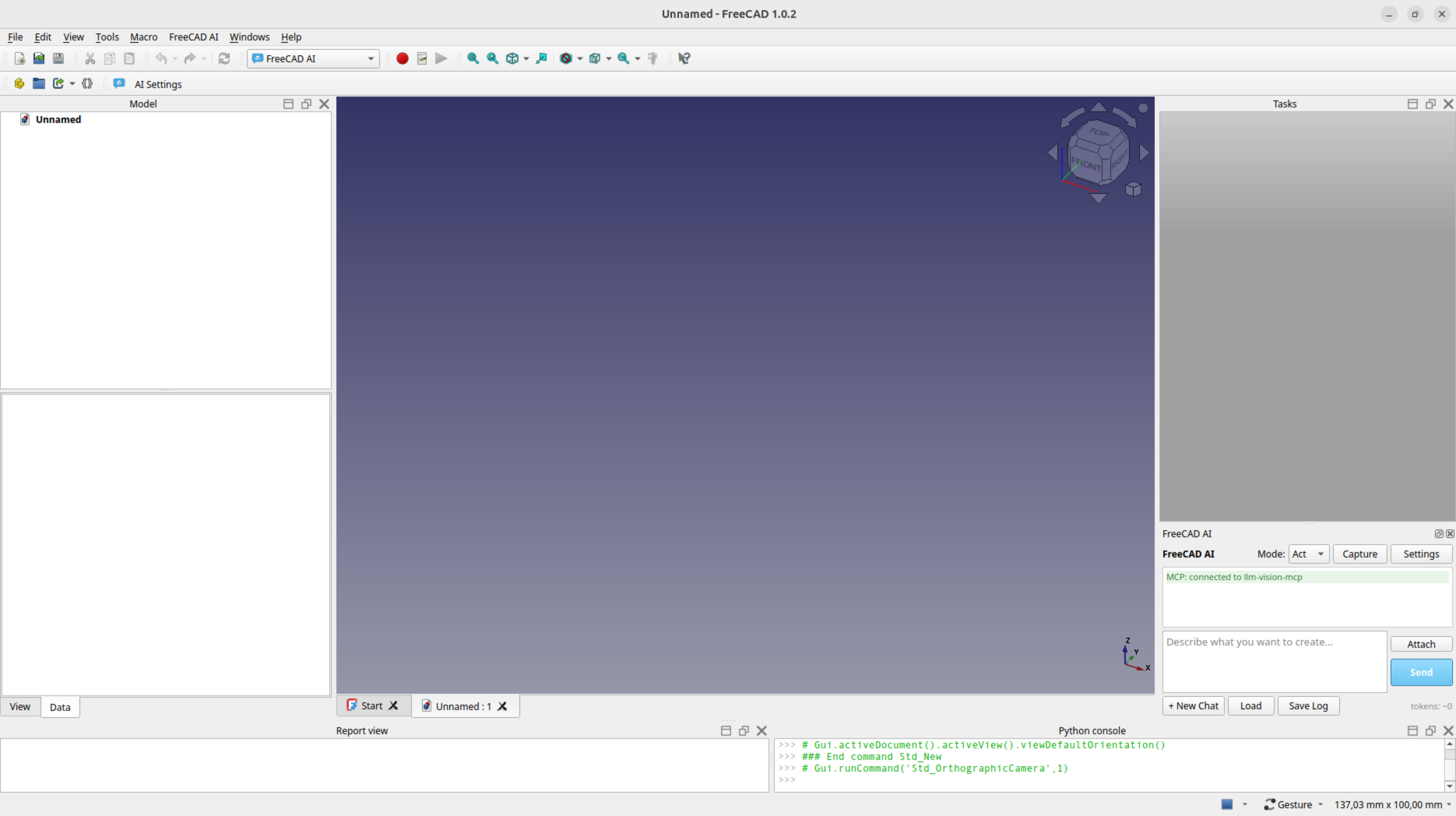
- The chat panel appears as a dock widget on the right side of the FreeCAD window. If it does not appear, go to View > Panels and enable "FreeCAD AI Chat".
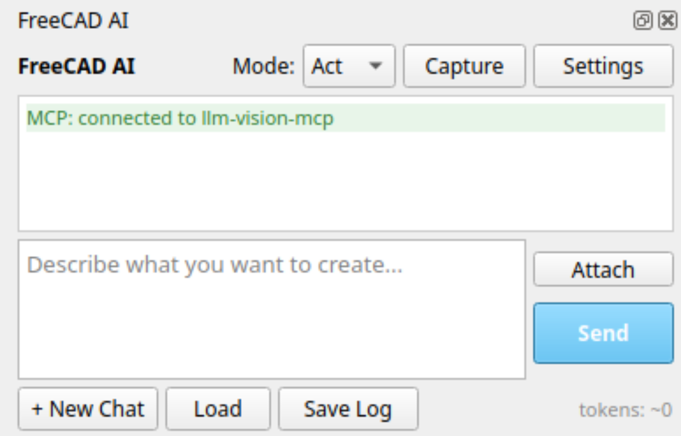 4. Configure your provider by clicking the gear icon at the bottom of the chat panel. You need to set at least:
- Provider: Choose between Anthropic, OpenAI, Ollama (local), or OpenRouter.
- API Key: Required for cloud providers (not needed for Ollama).
-
Model: Select or type a model name (e.g.,
claude-sonnet-4-6,gpt-4o,qwen3:32b).
Once configured, you can start typing in the chat input and press Enter to send a message.
The workbench has two execution modes, selectable via the dropdown at the top of the chat panel.
Plan mode is the review-first approach. When you ask the LLM to create or modify geometry:
- The LLM generates Python code and displays it in a fenced code block.
- The code is not executed automatically. You review it first.
- Each code block has Execute and Copy buttons:
- Execute: opens the Review Code dialog (see below) so you can validate and run the code.
- Copy: Copies the code to your clipboard so you can paste it into FreeCAD's Python console or a macro.
- If you ask a question (rather than a modeling request), the LLM answers normally without code.
Plan mode is ideal for learning, auditing what the AI produces, and situations where you want full control.
Clicking Execute on a Plan-mode code block opens a dialog with the proposed code and these controls:
| Button | Action |
|---|---|
| Edit / Lock | Toggle the editor between read-only and editable. Useful for tweaking code before running. |
| Check | Validate the code in a headless FreeCAD sandbox against a copy of the current document, without touching the live document. The sandbox catches not only Python exceptions but also FreeCAD's C++ console errors (e.g., invalid sketch constraints) and invalid resulting shapes (e.g., self-intersecting solids) — issues that don't raise Python exceptions and would otherwise pass silently. |
| Fix with AI | Compose a follow-up message and send it back to the LLM. If the most recent Check or Execute produced an error, the prompt is pre-filled with that error text; otherwise it's a blank template you fill in ("describe what to change"). Either way the prompt is fully editable before sending. |
| Execute | Run the code in the live document. Wrapped in an undo transaction. |
| Cancel | Dismiss the dialog without running anything. |
Auto-attached viewport on retry: when the LLM is asked to fix a failed run, the workbench attaches a viewport screenshot to the retry message automatically — so the LLM can see what the document actually looks like after the partial execution, not just the error text.
Act mode is the auto-execute approach. It has two execution paths depending on your provider's capabilities:
Tool calling (default and preferred):
When the LLM provider supports function calling (Anthropic, OpenAI, and capable Ollama models), the LLM invokes structured tools like create_body, pad_sketch, fillet_edges, etc. Each tool call:
- Is wrapped in a FreeCAD undo transaction for safety.
- Automatically rolls back on error.
- Returns structured results that the LLM uses to plan the next step.
- Appears in the chat as a collapsible tool call block showing the tool name, parameters, and result.
The LLM can chain multiple tool calls in a single turn to build complex models step by step.
Code generation (fallback):
If the provider does not support tool calling, Act mode falls back to code generation. The LLM generates Python code blocks that are automatically extracted and executed. A confirmation dialog appears before execution unless you have enabled auto-execute in settings.
Let's create a simple box with fillets to see how the workbench works.
-
Make sure you have a new, empty document (File > New).
-
Set the mode to Plan using the dropdown at the top of the chat panel.
-
Type the following in the chat input and press Enter:
Create a box 50mm x 30mm x 20mm with 2mm fillets on all edges -
Review the generated code. The LLM will produce Python code that uses FreeCAD's Part or PartDesign API. It will typically:
- Create a
Part::Boxwith the specified dimensions, or - Create a PartDesign Body with a sketch, pad, and fillet features.
- Create a
-
Click Execute on the code block to run it.
-
Press V then F (or View > Fit All) to center the result in the 3D viewport.
-
Inspect the model tree on the left to see the created objects.
If something looks wrong, use Edit > Undo (Ctrl+Z) to roll back.
Now let's try the same thing with automatic tool execution.
-
Switch the mode to Act using the dropdown.
-
Type the following and press Enter:
Create a cylinder with radius 10mm and height 25mm -
Watch the tool calls execute automatically. In the chat, you will see the LLM invoke tools like:
-
create_primitivewithshape_type: "cylinder",radius: 10,height: 25
-
-
The cylinder appears in the viewport as soon as the tool completes.
-
The LLM confirms what it did in natural language after the tool call.
Try a parametric workflow:
Create a PartDesign body, then sketch a 40x25mm rectangle on the XY plane,
pad it 15mm, and add 3mm fillets on all top edges
The LLM will chain multiple tool calls:
-
create_body-- creates the PartDesign Body container -
create_sketch-- adds a rectangle sketch on XY, attached to the body -
pad_sketch-- extrudes the sketch 15mm -
measure(edges) -- identifies which edges are on top -
fillet_edges-- applies 3mm fillets to the top edges
Each step appears in the chat with its parameters and result. If any step fails, the undo transaction rolls it back.
Create a model where all dimensions are editable by the user:
Create a parametric box using a variable set for length (50), width (30), and height (20).
Make all dimensions editable.
The LLM will:
-
create_variable_set— creates named variables (length=50, width=30, height=20) -
create_body— creates a PartDesign Body -
create_sketch— creates a rectangle withwidth="Variables.length",height="Variables.width"(expression strings, not numbers) -
pad_sketch— extrudes withlength="Variables.height"
After creation, select the Variables object in the model tree and edit the values in the Data panel — the model updates automatically.
You can also use create_spreadsheet instead of create_variable_set if you prefer editing values in the Spreadsheet workbench.
Apply operations to groups of edges or faces using filter keywords:
Create a box 50x30x20mm and fillet all edges with 2mm radius
The LLM calls fillet_edges with edges=["all"] — no need to list all 12 edge names individually.
Other filter examples:
-
"Fillet only the vertical edges with 1mm radius"→edges=["vertical"] -
"Chamfer the top and bottom edges"→edges=["top", "bottom"] -
"Shell the box, remove the top face"→faces=["top"]
Change dimensions by percentage or offset:
Make the box 20% taller
The LLM calls modify_property with value="+20%". Also works with "*1.5" (multiply), "+5" (add 5mm), "-3" (subtract 3mm).
Work across multiple open documents:
List all open documents
Switch to the document "MyProject"
The LLM uses list_documents and switch_document. All subsequent tool calls operate on the active document.
Skills are reusable instruction sets that guide the LLM through complex, multi-step construction patterns. They are stored as Markdown files in <FreeCADAI dir>/skills/<name>/SKILL.md. (<FreeCADAI dir> resolves to ~/.config/FreeCAD/v1-1/FreeCADAI/ on FreeCAD 1.1+ Linux, ~/.config/FreeCAD/FreeCADAI/ on older FreeCAD — see Configuration#configuration-paths for the full resolution order and migration notes.)
Type a slash command in the chat input to invoke a skill:
/enclosure 80x60x40mm, 2mm walls, snap-fit lid
When you invoke a skill:
- The skill's SKILL.md instructions are injected into the LLM prompt for that conversation turn.
- The LLM follows the step-by-step construction pattern defined in the skill.
- The LLM uses the standard tools (in Act mode) or generates code (in Plan mode) according to the skill's instructions.
The built-in enclosure skill demonstrates a complex multi-step workflow:
- Creates a PartDesign Body for the base.
- Sketches and pads the outer shell.
- Pockets the interior to create a hollow box.
- Creates a lid using
create_enclosure_lid(computes lip geometry automatically). - Positions the lid at the correct height.
- Adds an inner ridge to the base for snap-fit.
- Adds snap tabs to the lid that catch on the ridge.
- Hides construction sketches for a clean model tree.
This typically requires 15-20 tool calls and runs automatically in Act mode.
Create a new directory under <FreeCADAI dir>/skills/ with a SKILL.md file:
<FreeCADAI dir>/skills/my-skill/SKILL.md
The SKILL.md file should contain:
- A heading with the skill name.
- A description of what the skill does.
- Step-by-step instructions for the LLM to follow.
- Any constraints or parameters the LLM should respect.
The skill is automatically discovered and available via /my-skill in the chat.
- User messages appear right-aligned with a colored background.
- Assistant messages appear left-aligned with Markdown rendering (code blocks, lists, etc.).
- Tool calls appear as collapsible blocks showing the tool name, parameters (as JSON), and the result.
- Errors appear in red with the error message.
- Enter sends the message.
- Shift+Enter inserts a newline (for multi-line messages).
- Up arrow (when the caret is at the very top of the input) walks back through your prior messages in the current conversation, shell-style. Down arrow (when the caret is at the very end) walks forward; past the newest entry it restores whatever draft you'd typed before starting to navigate. Off-edge Up/Down keep their normal cursor-movement behavior so multi-line editing still works. History resets to the current conversation when you switch via Load or New.
- The mode dropdown (Plan/Act) switches execution modes.
- The gear icon opens the settings dialog.
- The Send button doubles as Stop while the AI is working — clicking it interrupts the agentic loop. This is the only brake when Settings → Max tool-loop turns is set to
0(endless). - The Capture button cycles viewport screenshot mode. Click repeatedly to switch between three states:
- Off (default styling) -- no automatic screenshots.
- Every message (blue text) -- attaches a viewport screenshot to every chat message you send.
- After changes (green text) -- attaches a screenshot only after tool calls modify the document. This is a session-only override; the persistent default is set in Settings > Behavior > Viewport capture.
- The Attach button opens a file picker to attach files to your message:
- Images (PNG, JPG, etc.) -- sent as vision blocks to the LLM.
- Text files (TXT, MD, CSV, PY, JSON, XML, etc.) -- read as text and included in the message.
-
Binary files (PDF, DOCX, XLSX, etc.) -- converted via a
file_attachhook or blocked with a helpful message. See Configuration — Hooks.
- Drag-and-drop files anywhere on the chat panel (input area, chat history, attachment strip).
- Paste (Ctrl+V) works for images and text file paths.
- Files are detected as binary by magic bytes (PDF, ZIP/Office, PNG, etc.) and null-byte scanning — unknown text formats are accepted regardless of extension.
Image-specific controls (Capture, image paste/drop) are automatically disabled if the LLM does not support vision and no MCP fallback is available. The Attach button stays enabled for text/document files. Run Test Connection in Settings to detect vision support. See Configuration — Vision Routing for details.
- New: Starts a fresh conversation (clears chat history).
- Load: Opens a dialog to resume a previously saved session (shows the last 20 sessions).
- Settings (gear icon): Opens the full settings dialog.
- Save your FreeCAD document before using Act mode. While tool calls are wrapped in undo transactions, complex multi-step operations are safer with a saved checkpoint.
- Start with Plan mode to understand what the AI will do, then switch to Act mode once you trust the patterns.
- Be specific about dimensions. "Create a box" is vague; "Create a box 50x30x20mm" gives the LLM clear parameters.
- Use metric units (mm). FreeCAD defaults to millimeters, and all tool parameters expect mm values.
- The LLM automatically sees your document state (object names, types, dimensions) with each message. You do not need to describe what is already in the model.
- Reference objects by name. After creating objects, the LLM knows their internal names and can reference them in subsequent operations.
- Multi-turn conversations work. You can iteratively refine: "Make it taller", "Add fillets to the bottom edges", "Change the radius to 8mm".
- Failed operations are rolled back via undo transactions. The LLM sees the error and can retry with corrected parameters.
- If the LLM produces incorrect code in Plan mode, do not execute it. Ask the LLM to fix the issue or adjust your prompt.
- If a tool call fails in Act mode, check the error message in the tool result block. Common issues:
- "No active document" -- create or open a document first.
- "Body not found" -- the body name may have been renamed by FreeCAD; use
get_document_stateto check. - "Sketch not found" -- same naming issue; FreeCAD may assign different internal names than requested.
- If the model seems stuck or generates nonsensical output, click New to start a fresh conversation.
- Check the session log at
<FreeCADAI dir>/logs/latest_session.jsonfor debugging.
Next: Tool Reference | Configuration