Baseboard
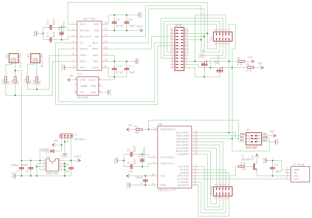
The baseboard is responsible for the following tasks:
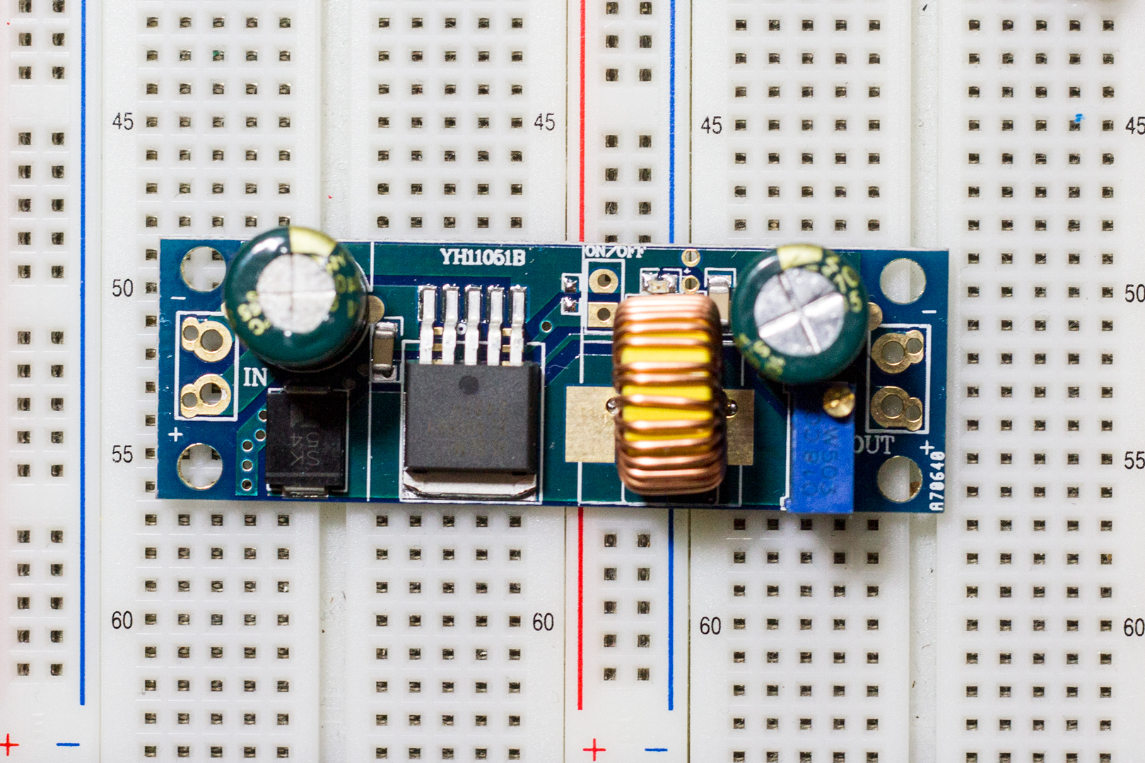
- Generating 5V power supply
- Generating 3.3V power supply
- Measuring the battery voltage
- Controlling the stepper motors
- Decoding the data from the Rx35 receiver
- Level shifting the 3.3 V I²C-Bus to 5 V
- ATtiny2313 (8-bit Microcontroller)
- AD 7705 (2-Channel, 16-Bit, Sigma-Delta ADC)
- Deltan Rx35 (2.4 GHz Receiver)
- MAX 604 (3.3V, 300mA Linear Regulator)
![Baseboard Schematics] (https://raw.githubusercontent.com/ni-c/eve/master/documents/img/baseboard.png)
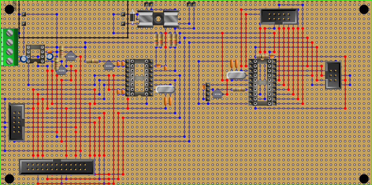
![Baseboard] (https://raw.githubusercontent.com/ni-c/eve/master/documents/img/baseboard_bb.png)
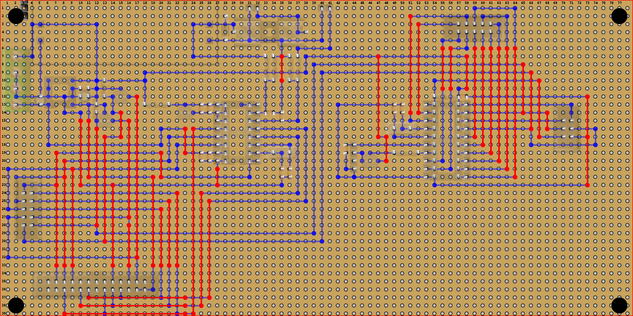
![Baseboard Back] (https://raw.githubusercontent.com/ni-c/eve/master/documents/img/baseboard_bb_back.png)
AtTiny   Conn.    TB6550   Description
======================================
PD4  ->  P1   ->   P1      Enable
PD0  ->  P2   ->   P3      Dir X
PD5  ->  P3   ->   P4      Step Y
PD1  ->  P4   ->   P5      Dir Y
PB4  ->  P5   ->   P7      Dir Z
PD6  ->  P6   ->   P18-25  GND
PB3  ->  P7   ->   P6      Step Z
PB0  ->  P8   ->   P14     Relay control signal
PB2  ->  P9   ->   P2      Step X
PB1  ->  P10  ->   P18-25  GND
0x00-0x01: Control register (en- and disable function etc)
  0x00 Bit 1: RX En/Disable
  0x00 Bit 2: Direction Motor X
  0x00 Bit 3: Direction Motor Y
  0x00 Bit 4: Direction Motor Z
  0x00 Bit 5: TB6550 En/Disable
0x02-0x03: Remaining steps stepper 1
0x04-0x05: Remaining steps stepper 2
0x06-0x07: Remaining steps stepper 3
0x08-0x09: Speed stepper 1
0x0a-0x0b: Speed stepper 2
0x0c-0x0d: Speed stepper 3
0x0e-0x0f: Add steps to stepper 1
0x10-0x11: Add steps to stepper 2
0x12-0x13: Add steps to stepper 3
0x14: RX Channel 1
0x15: RX Channel 2
0x16: RX Channel 3
0x17: RX Channel 4
0x18: RX Channel 5
0x19: RX Channel 6
0x1a: RX Channel 7
0x1b: RX Channel 8