3. Board Installation
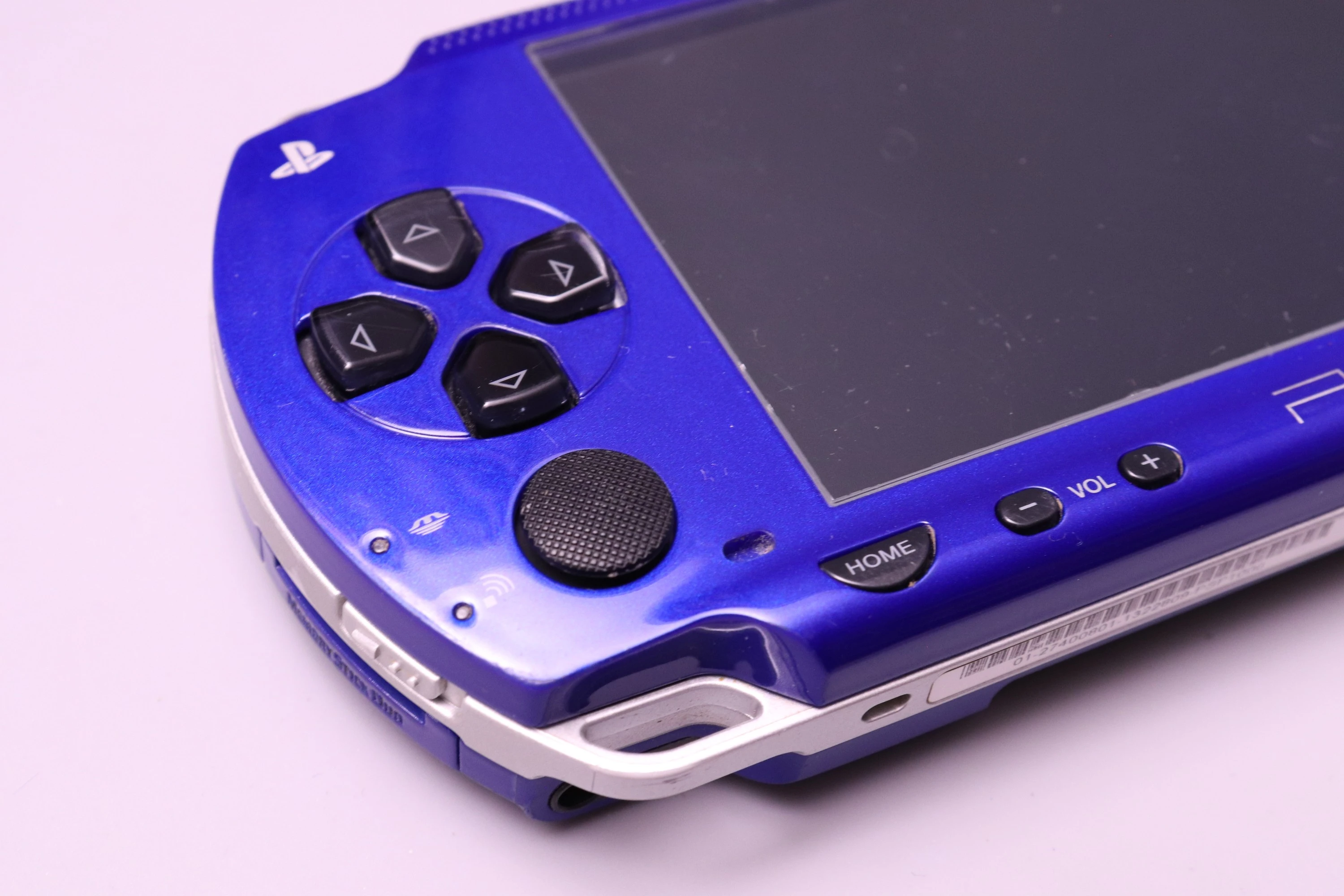
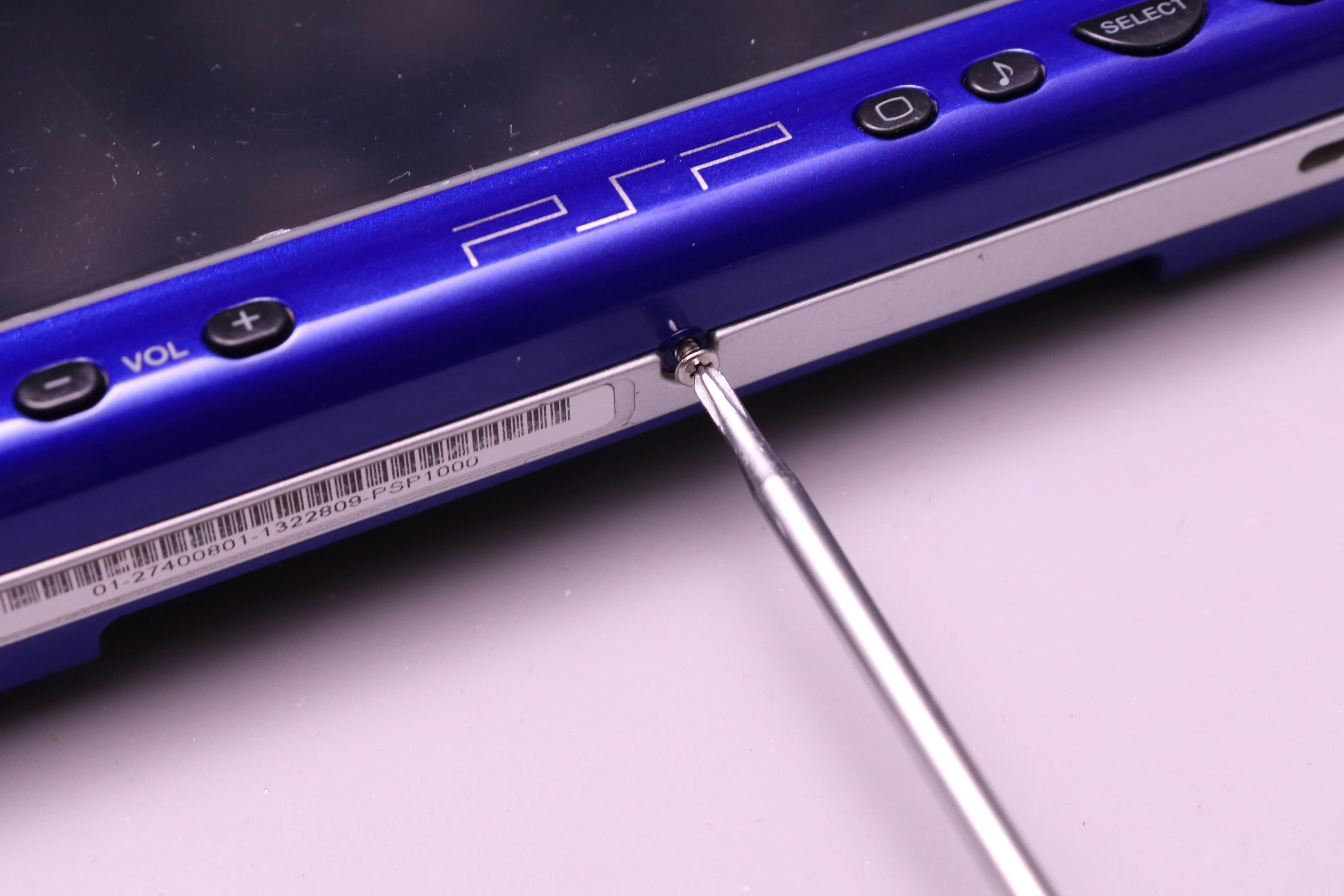
This guide covers the installation of the PSPi 6 board into a PSP 1000 shell.
- PSP 1000 Series Parts
- PSPi 6 Mainboard
- 800x480 LCD
- Raspberry Pi
- Battery
- Headphone Board (Optional)
- CM4 Carrier (Optional)
For more details, go to Components Required.
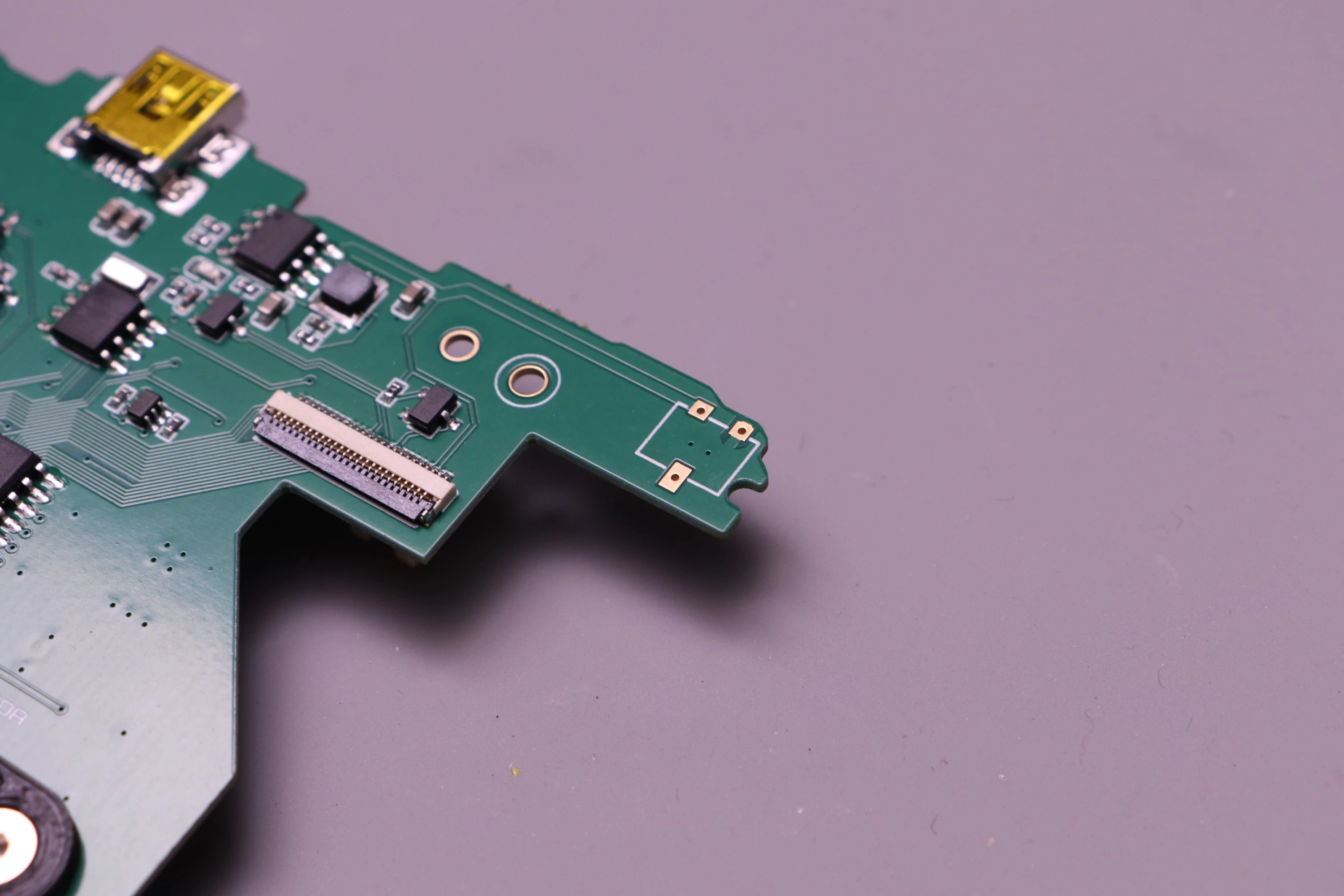
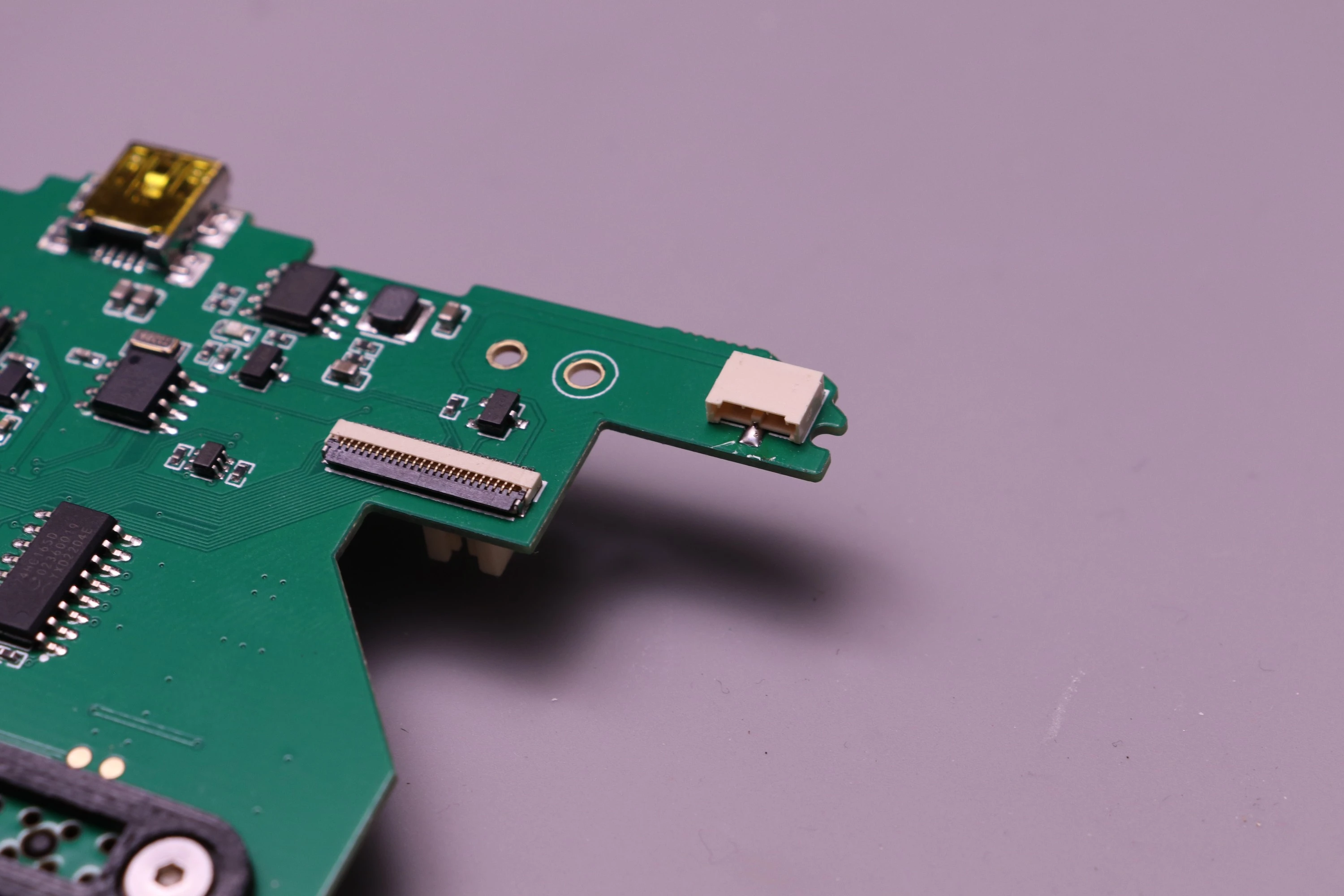
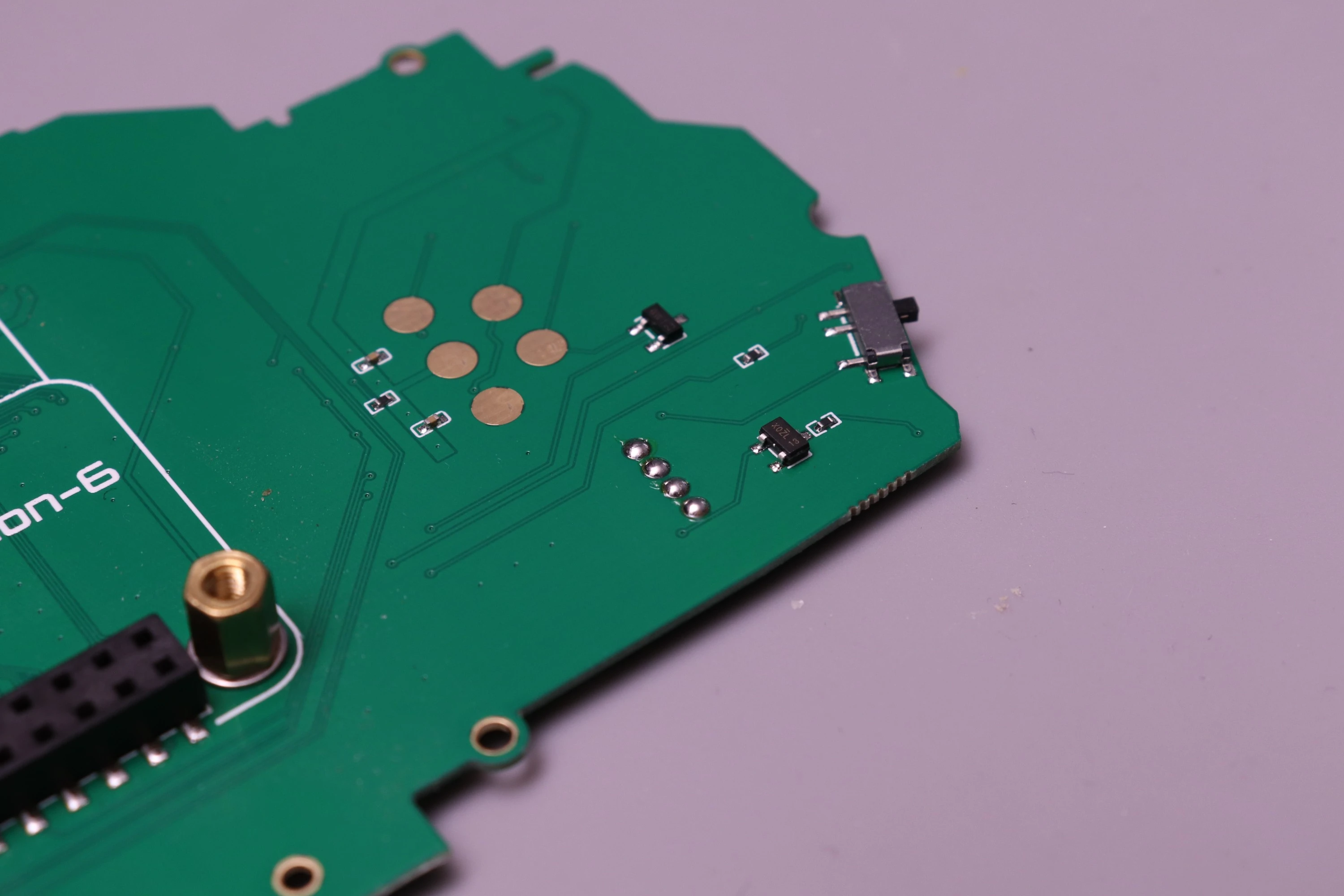
If you ordered the board without Solder Service, the DC Barrel Jack Connector and the Gold Plated Joystick Contact Pads are not soldered to the board and will arrive in a separate bag.
 |
 |
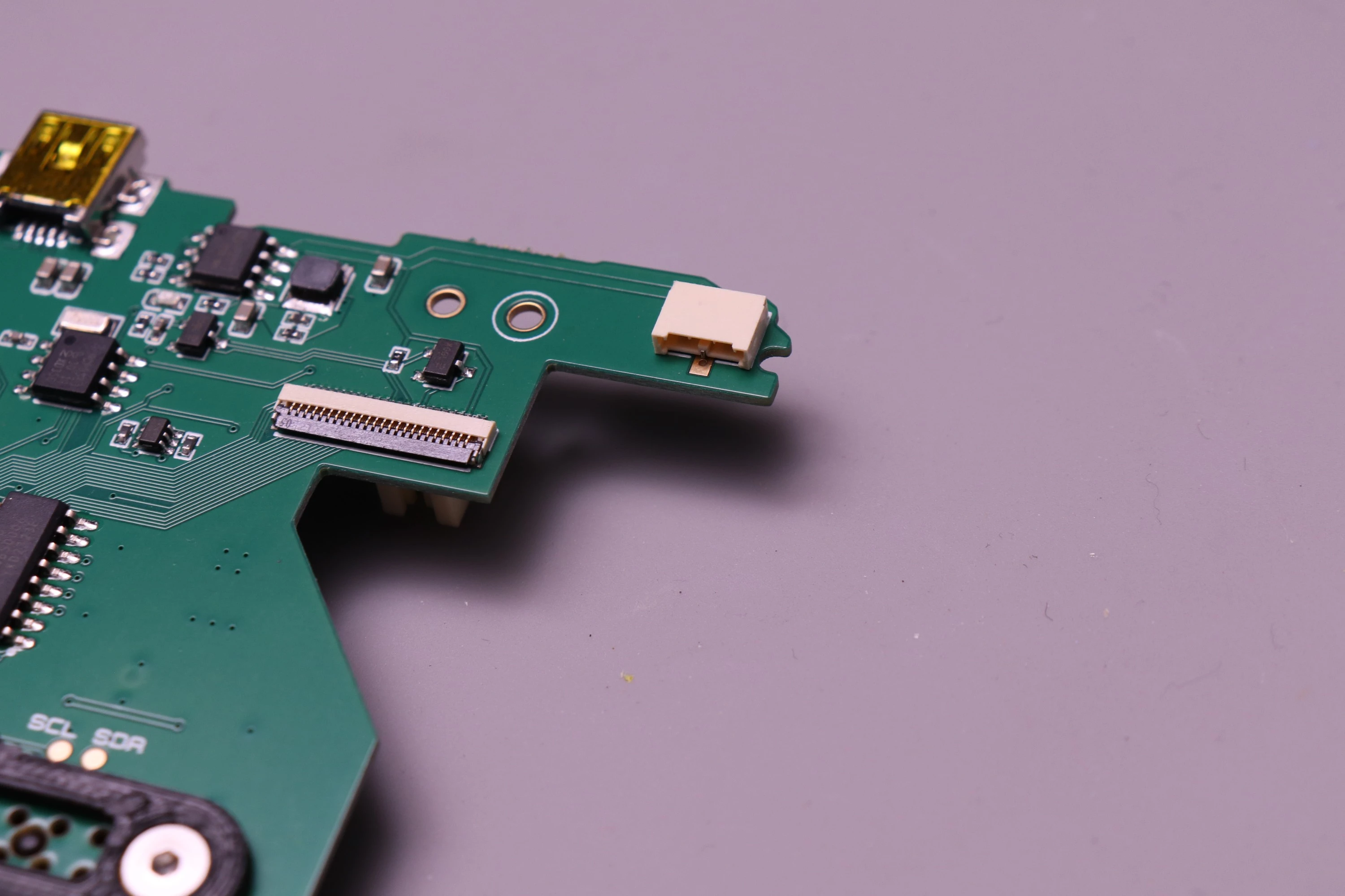
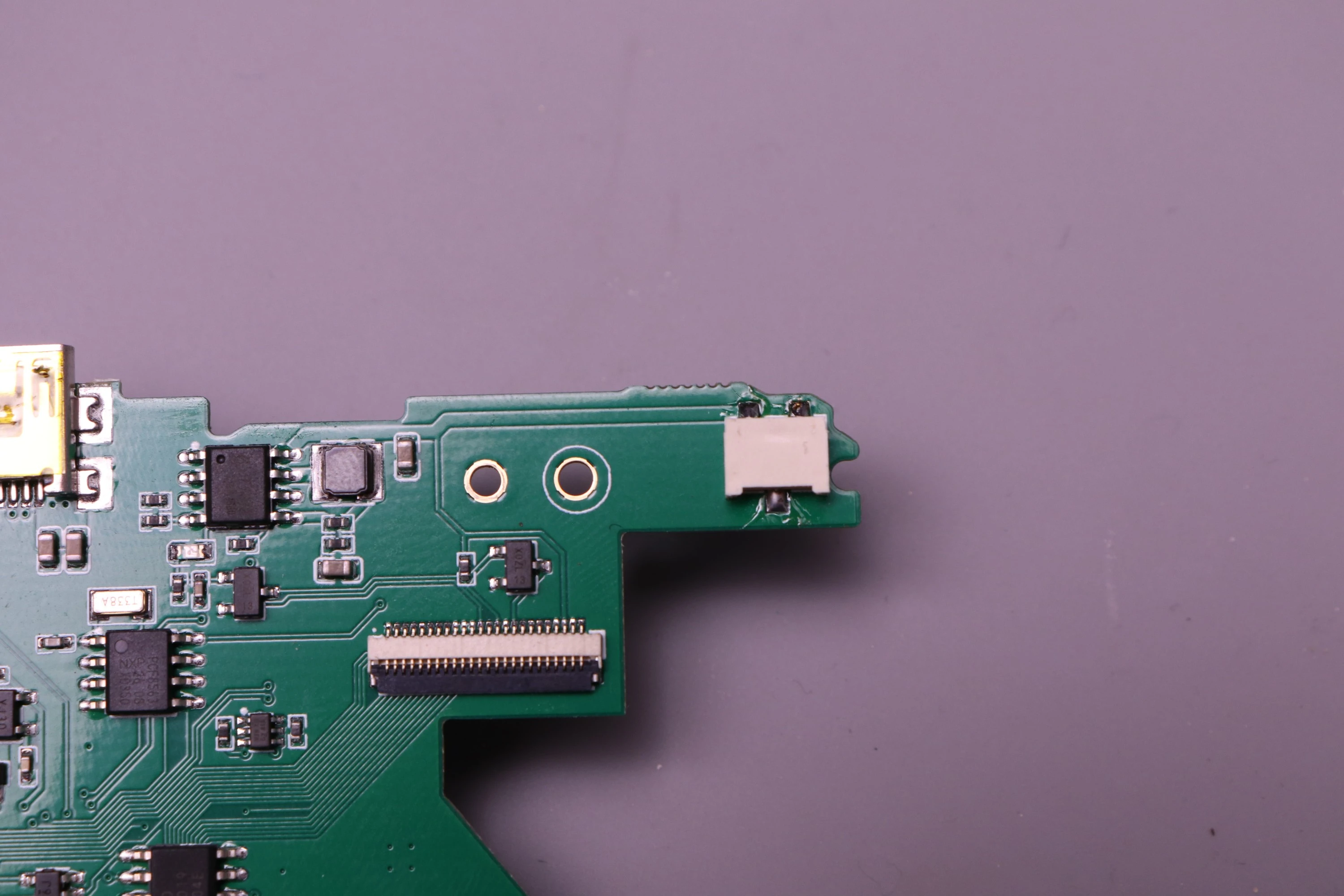
This connector allows you to charge the battery using the round DC jack. If this is a feature you don't need, then this soldering is not mandatory and you can still charge using the miniUSB port.
To solder the connector, start by placing it onto the three pads. I find it easiest to apply a small dot super glue to the board before placing the connector, and then allowing it to cure before beginning to solder. This keeps everything in position while soldering. The jack has an outline drawn on the board that you match the connector to.
 |
 |
 |
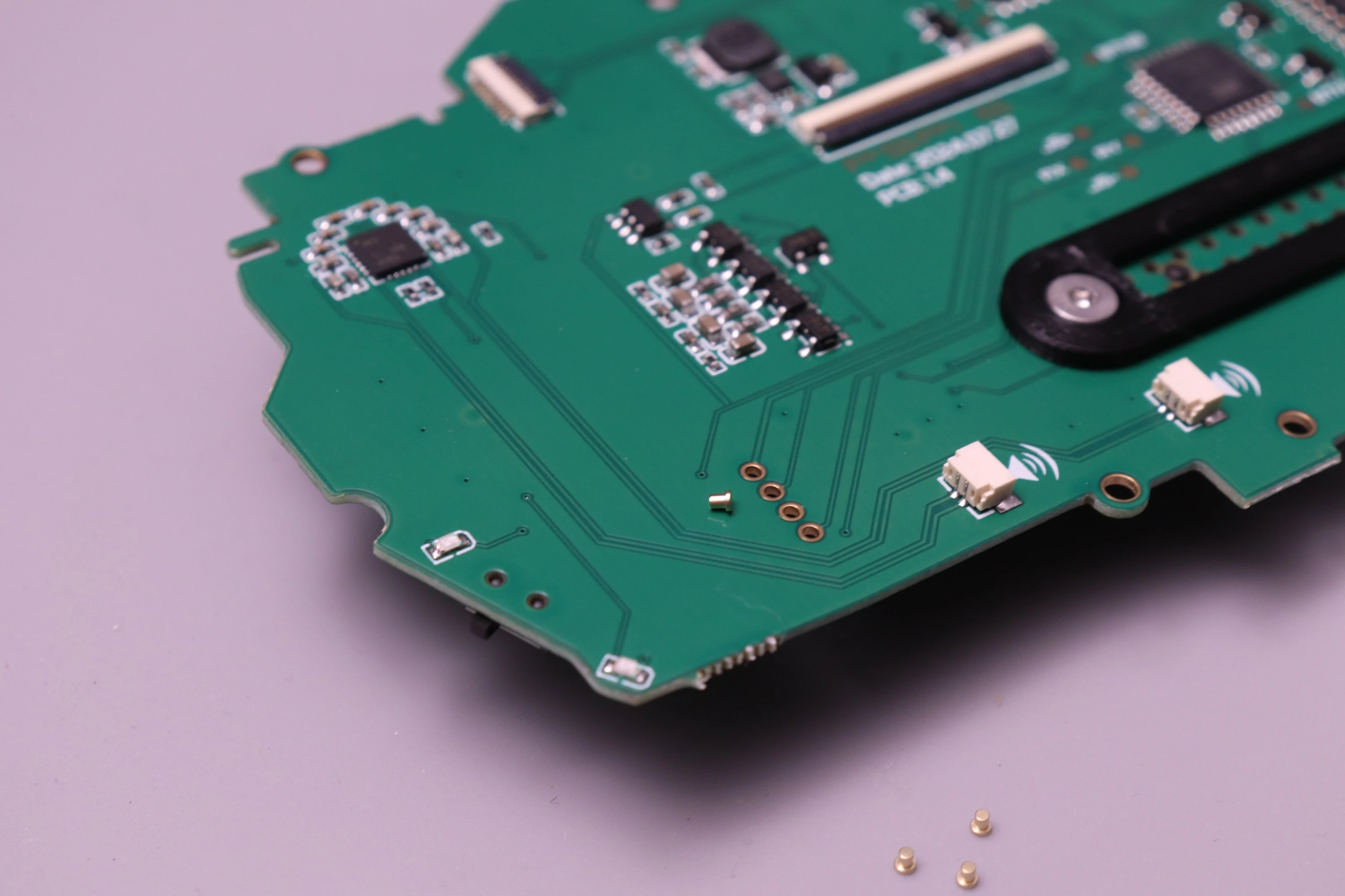
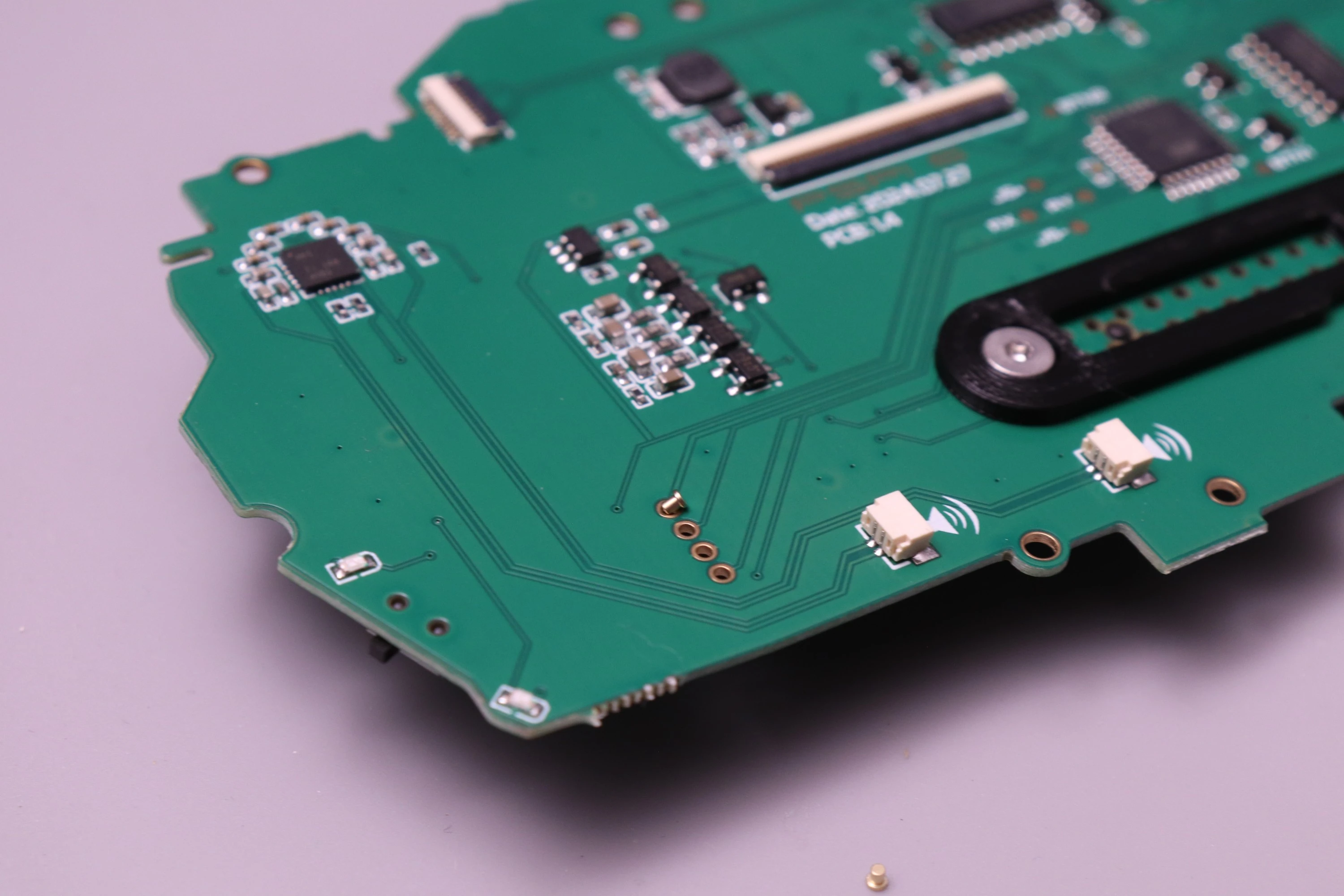
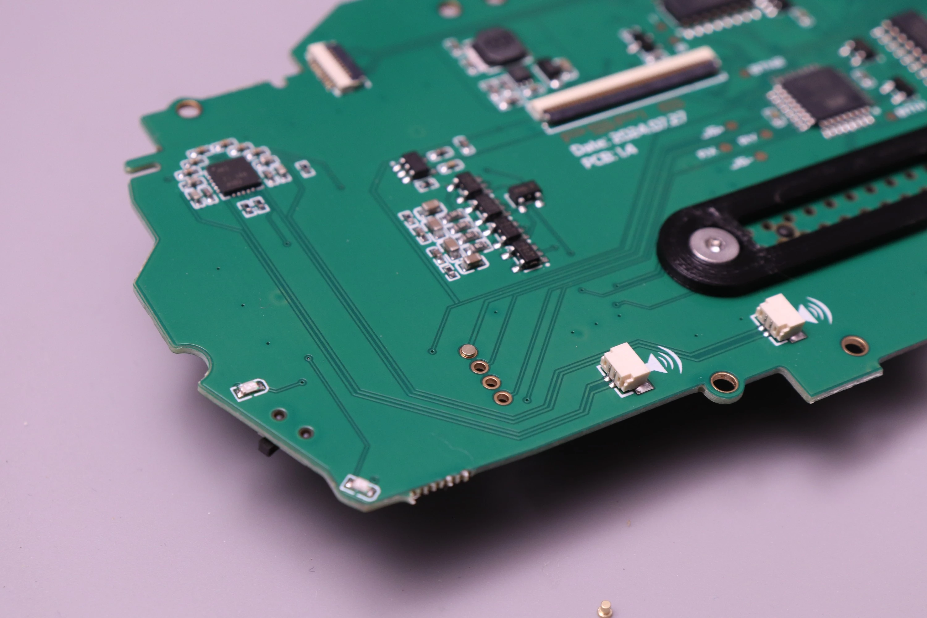
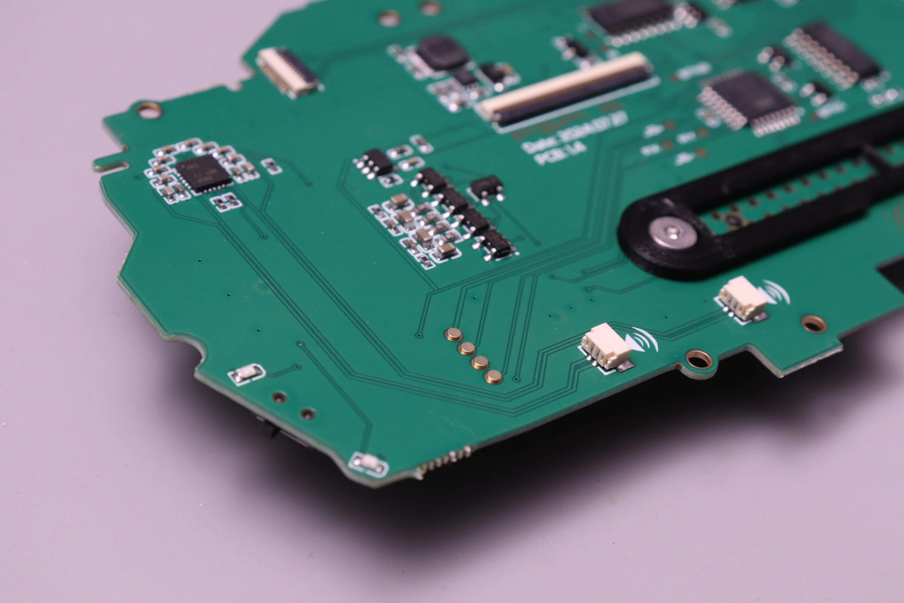
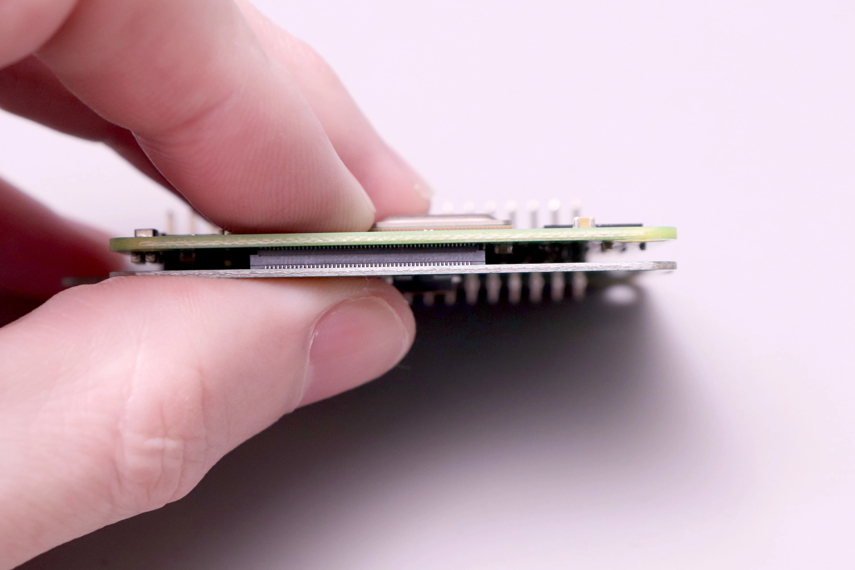
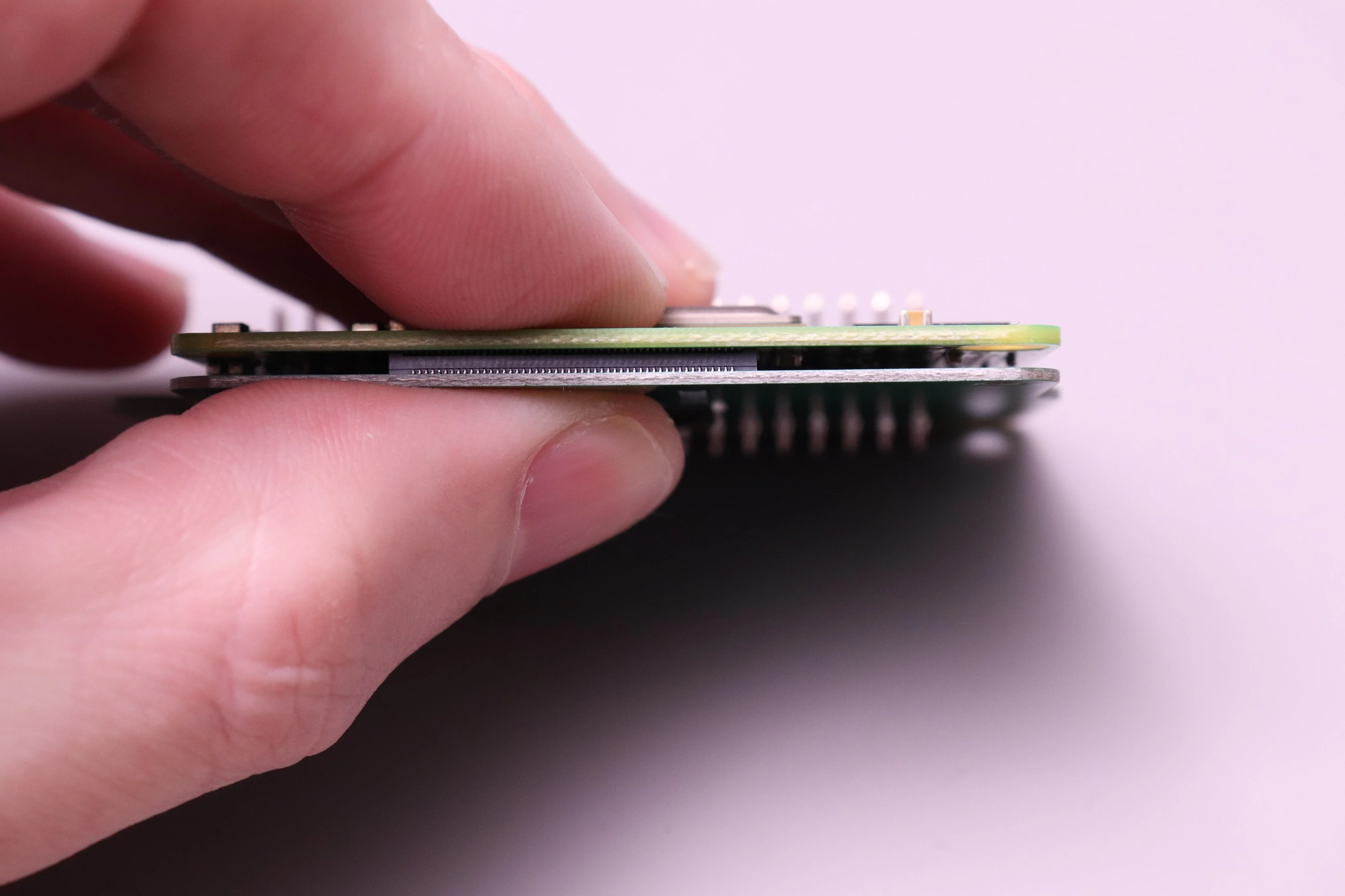
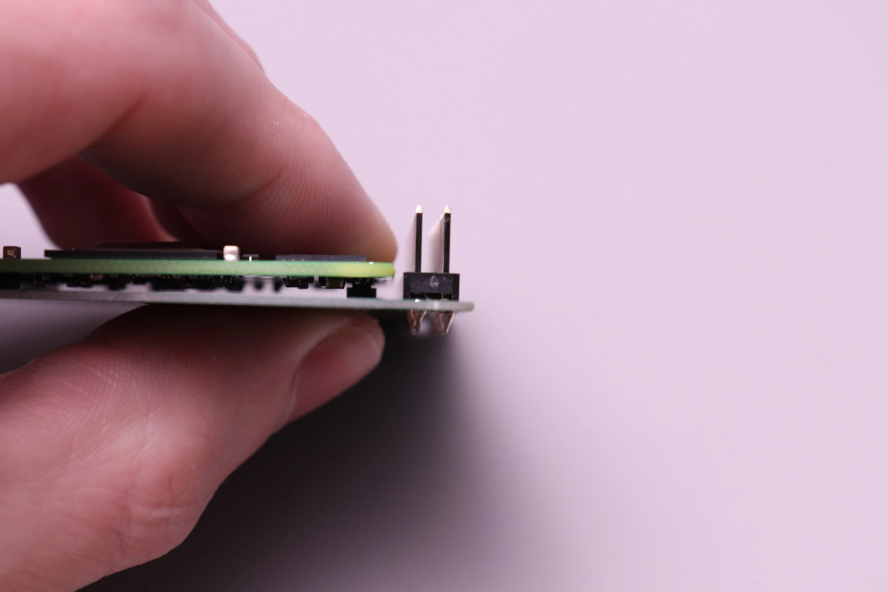
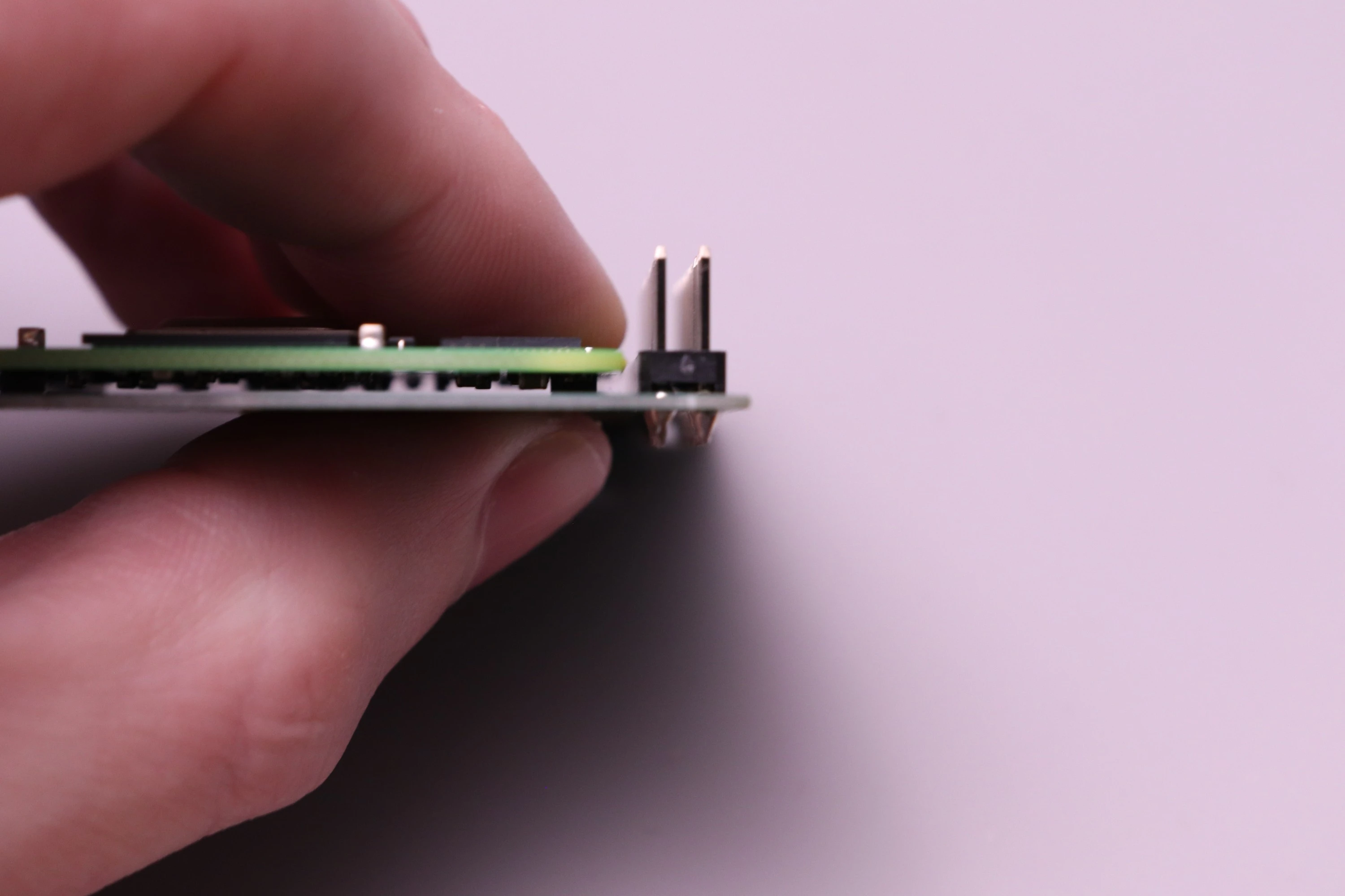
Earlier versions of the board required these to be soldered, but now it's optional. I had these custom pins manufactured that fit through the holes on the board and provide the connection needed. The board and pins are gold-plated, so the connection is reliable.
 |
 |
 |
 |
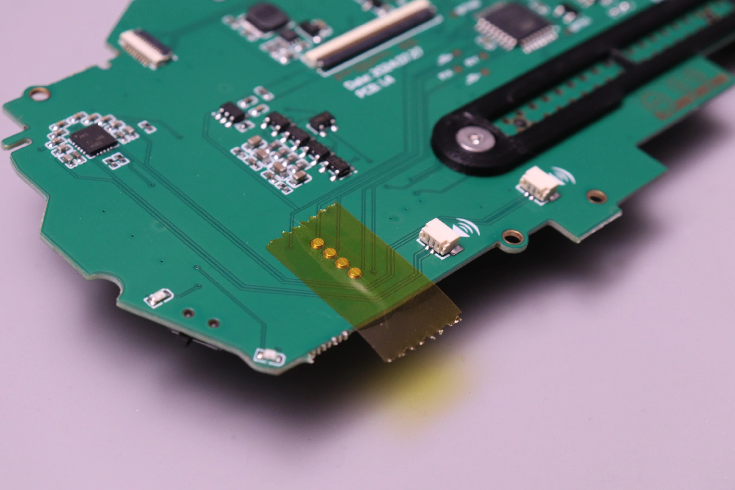
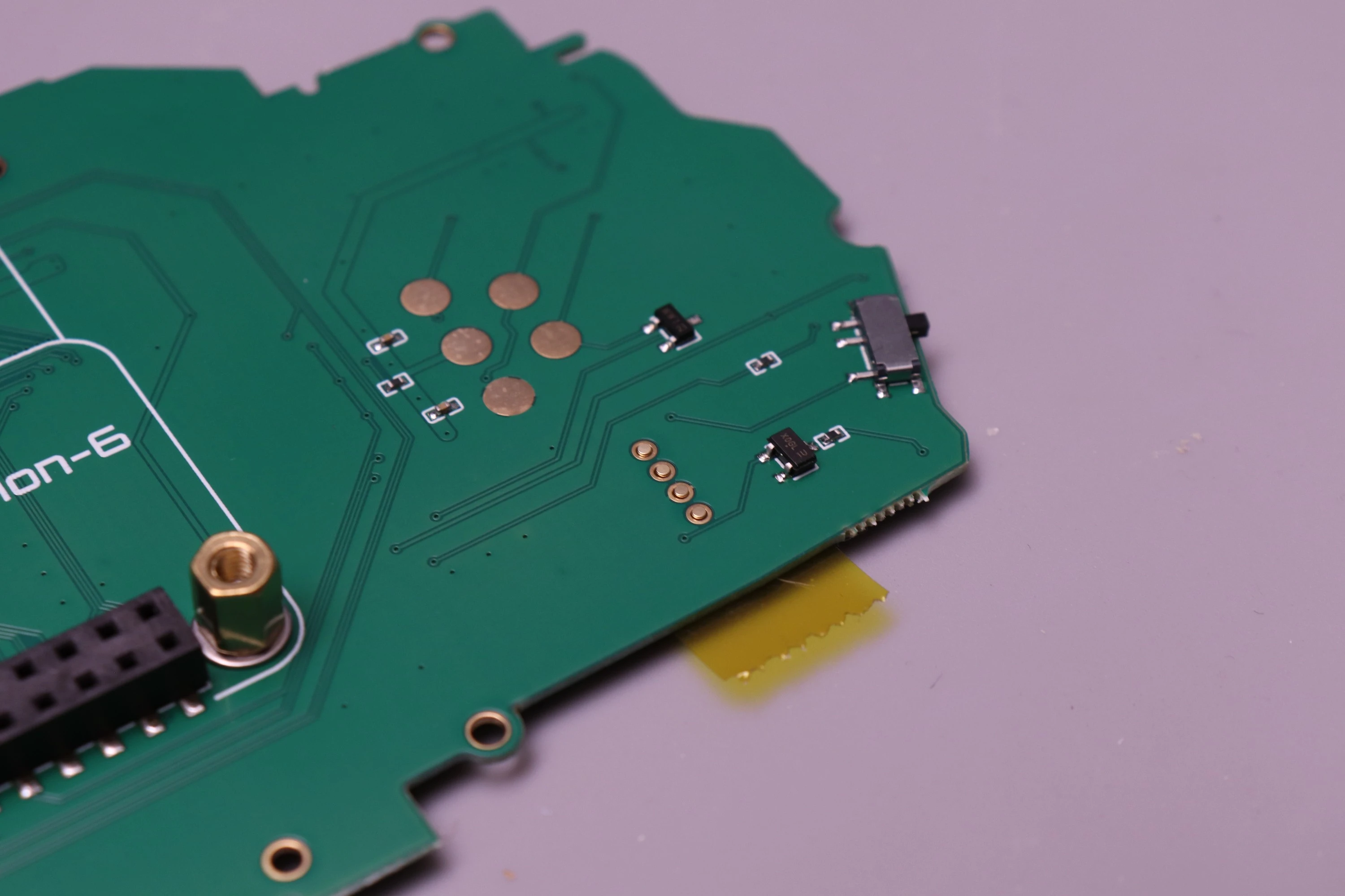
If you want to ensure that the pins won't be lost when disassembling later on, the joystick pads can be soldered in place. I find that the easiest way to do this is to use kapton tape on the front side to secure the pads flush with the board, and then solder from the back.
 |
 |
 |
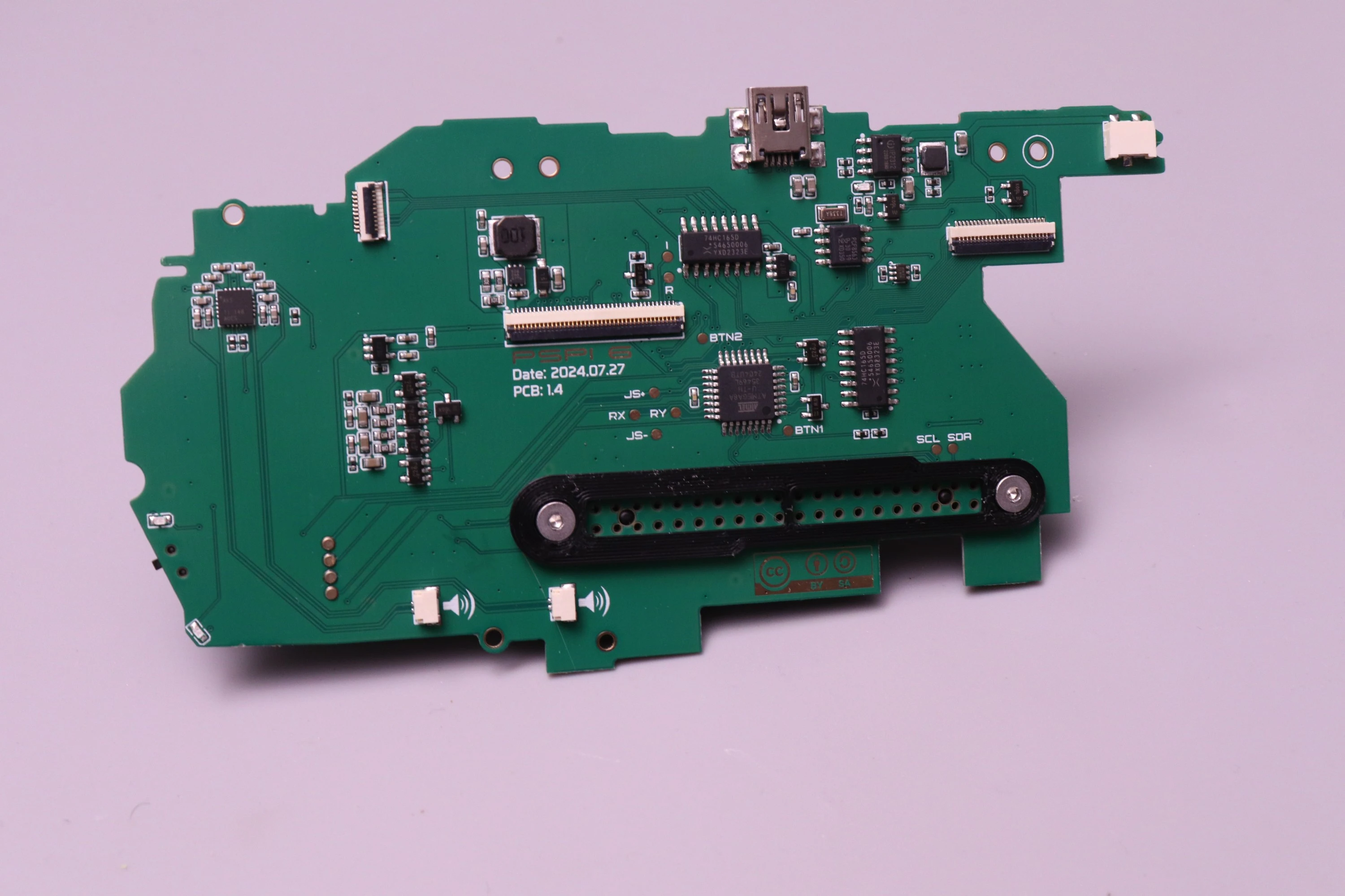 |
If you ordered the board with Solder Service, the barrel jack connector and joystick contact pads are already installed and soldered, and the board has been fully tested to verify every function works.
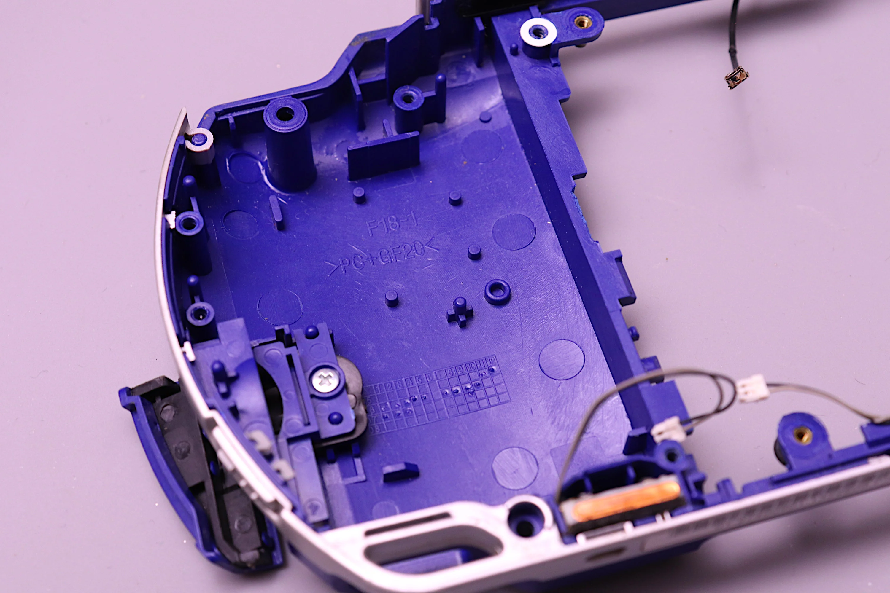
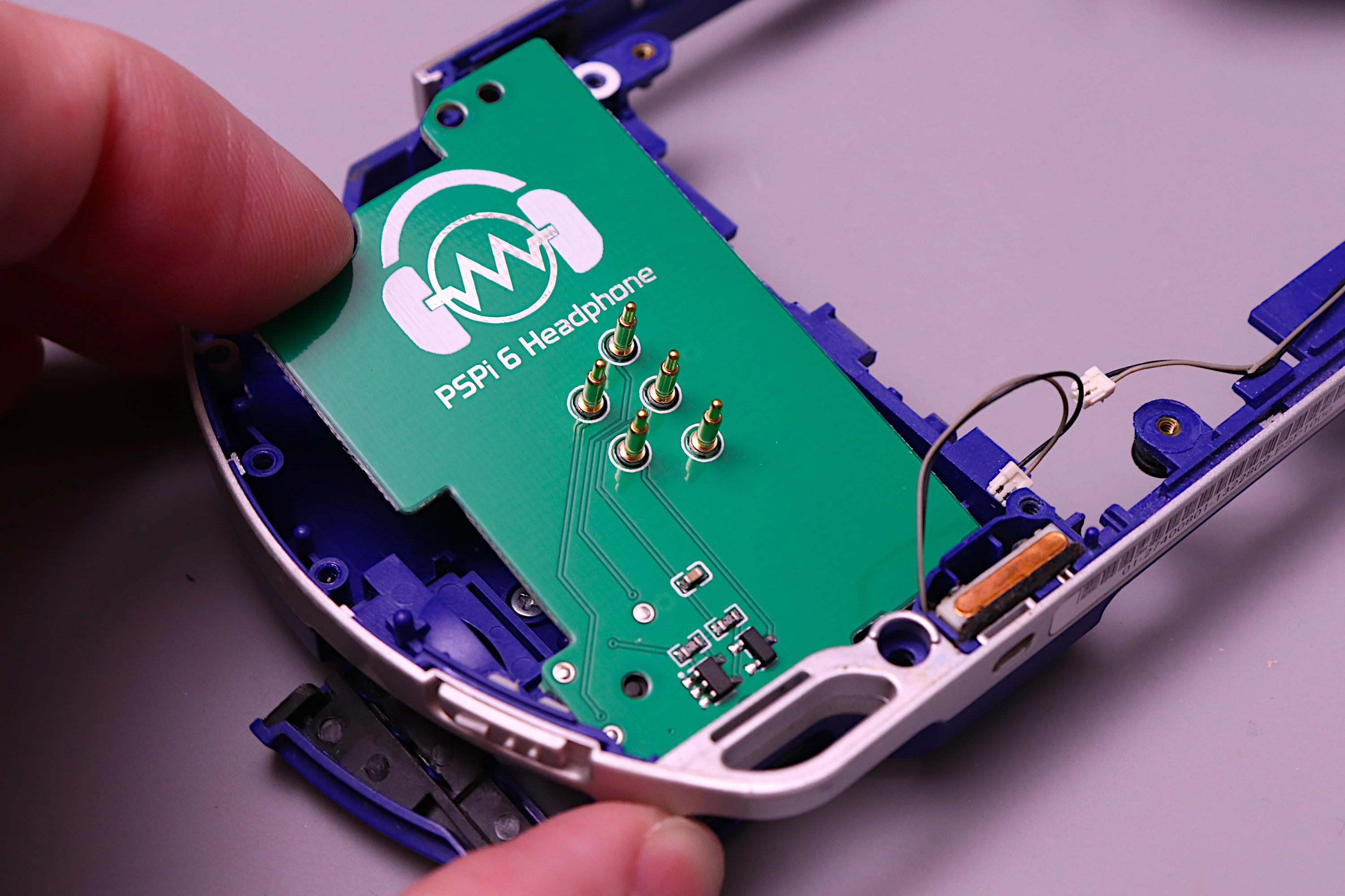
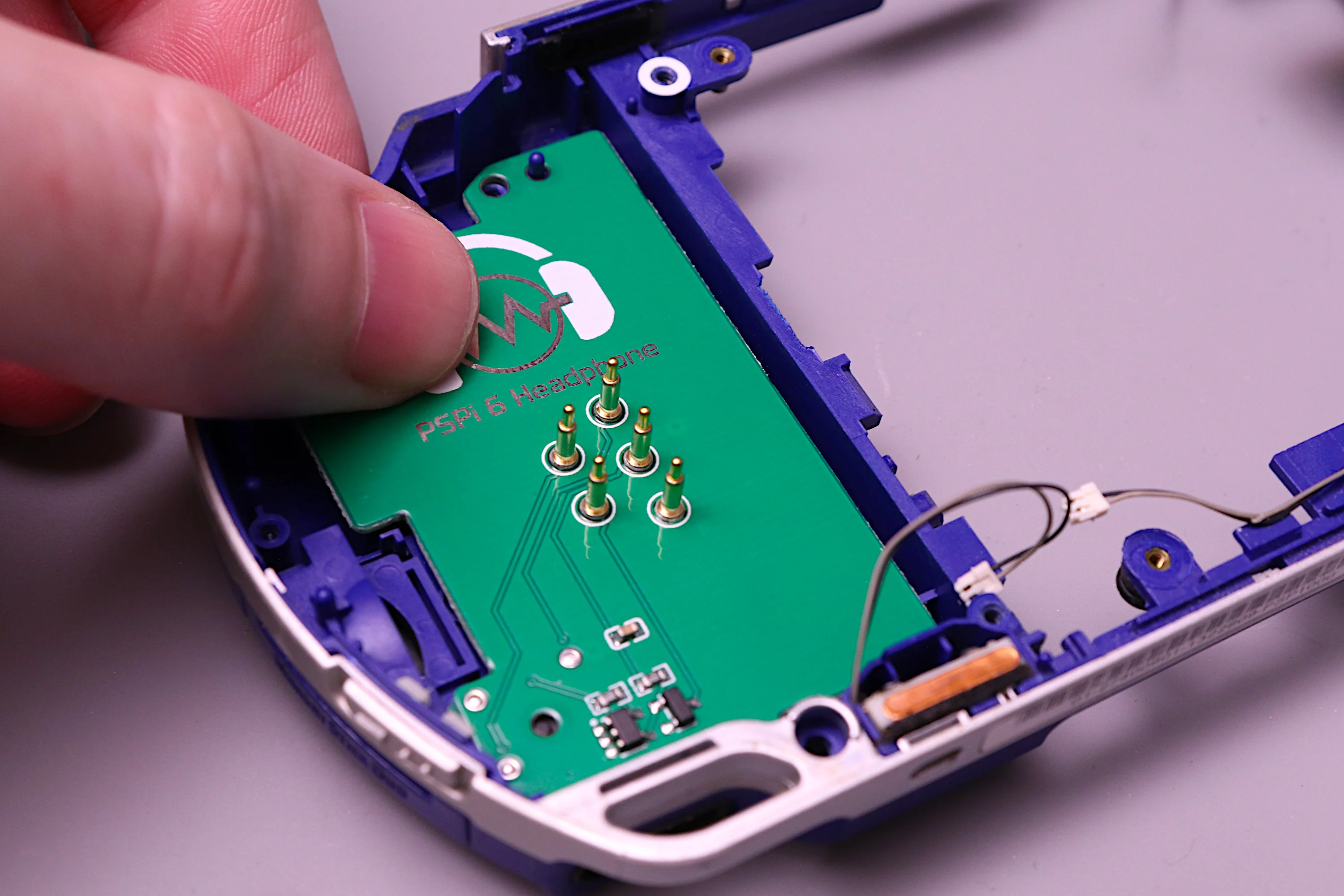
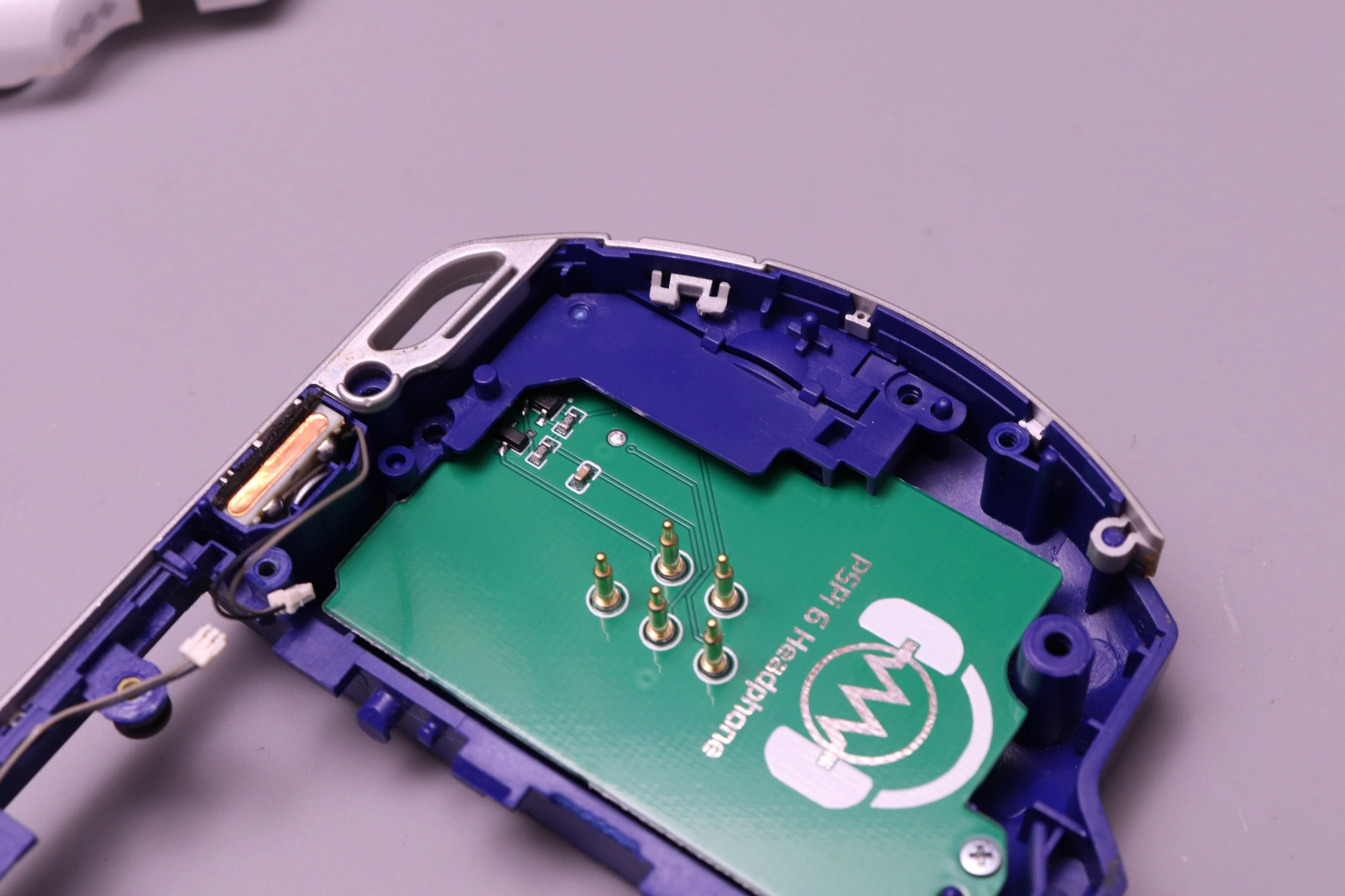
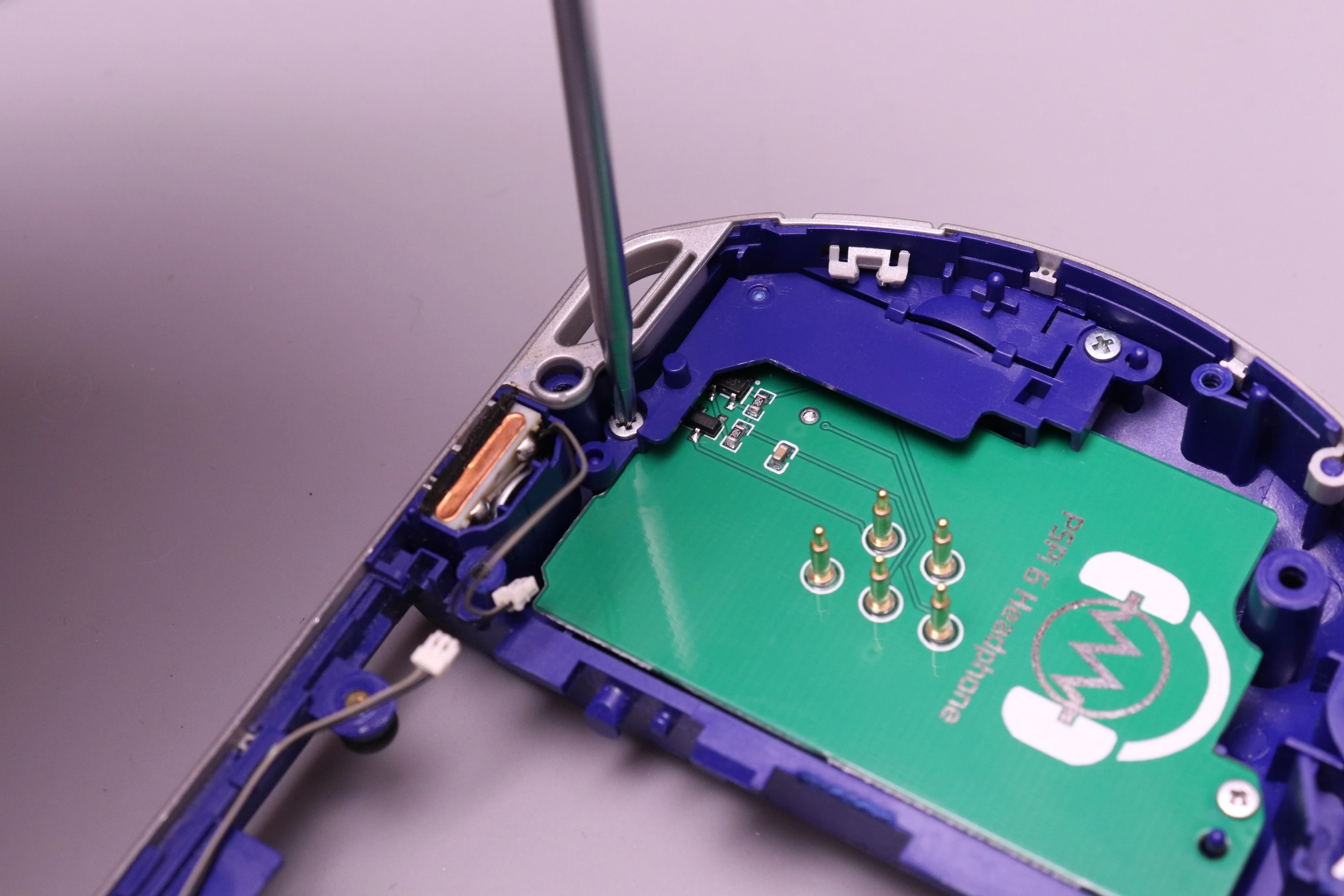
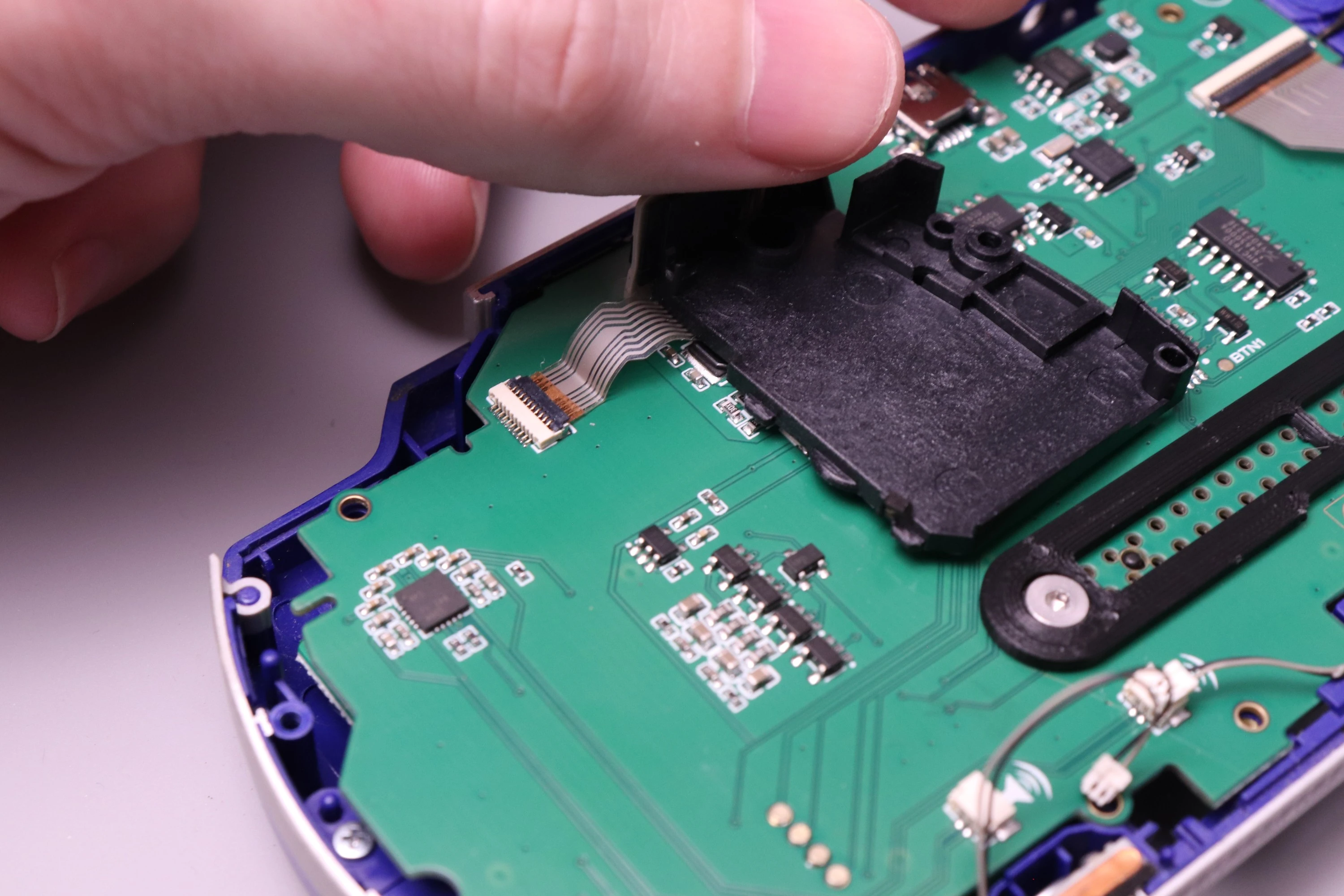
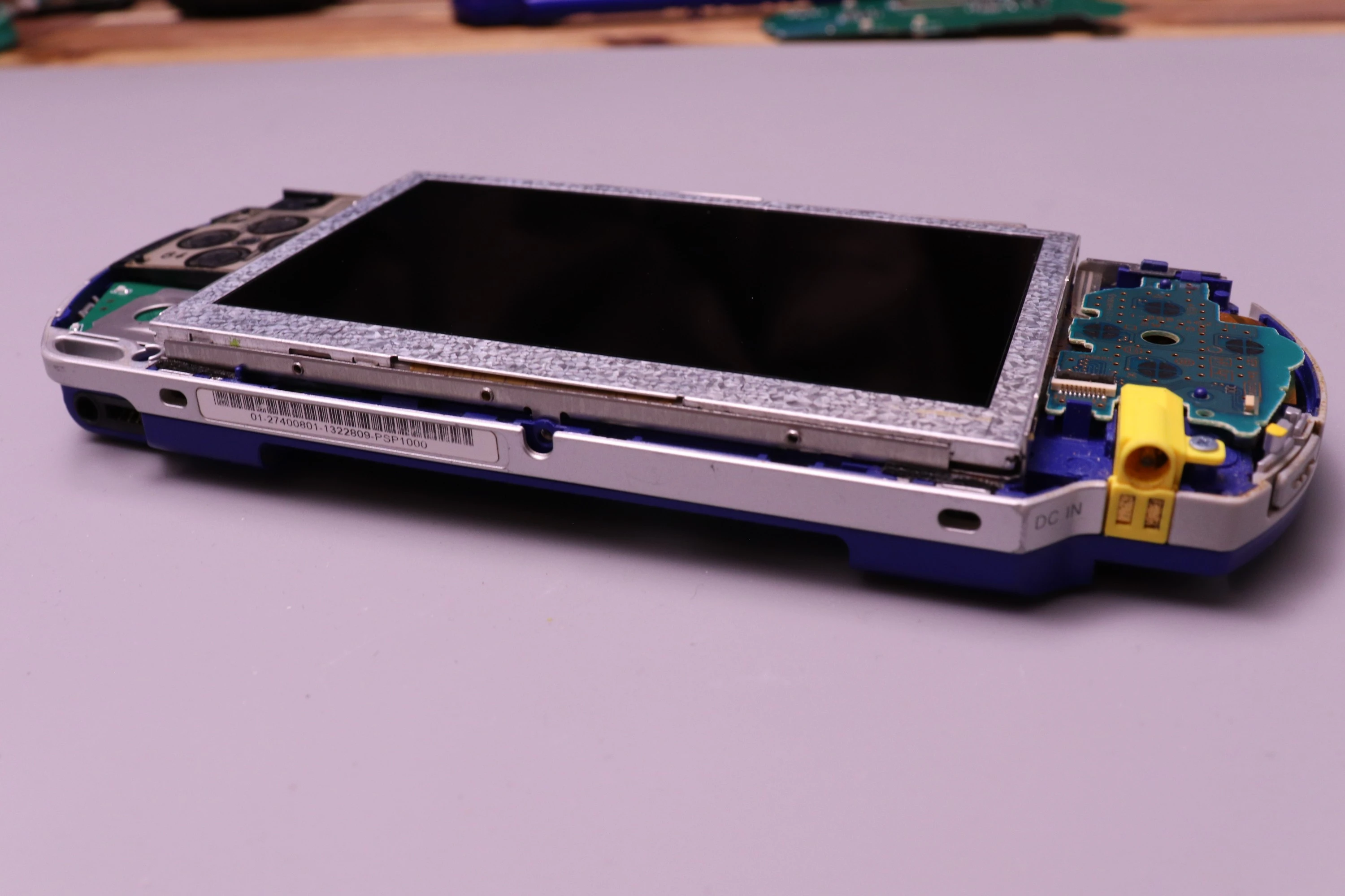
The headphone board slots into the same position as the original PSP headphone and memory reader board, and it uses pogo pins to make contact with the PSPi 6 mainboard, so no soldering or wiring is required.
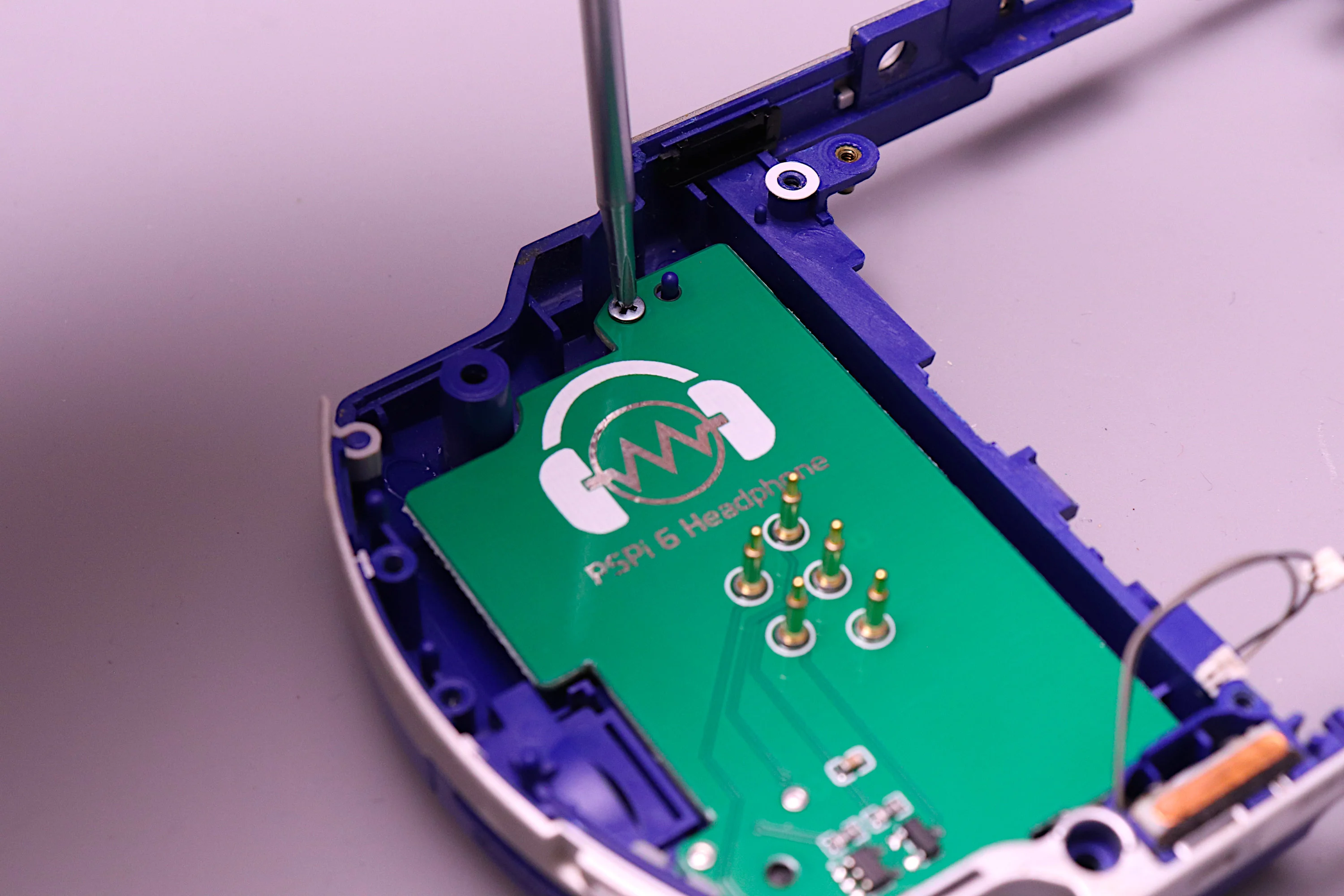
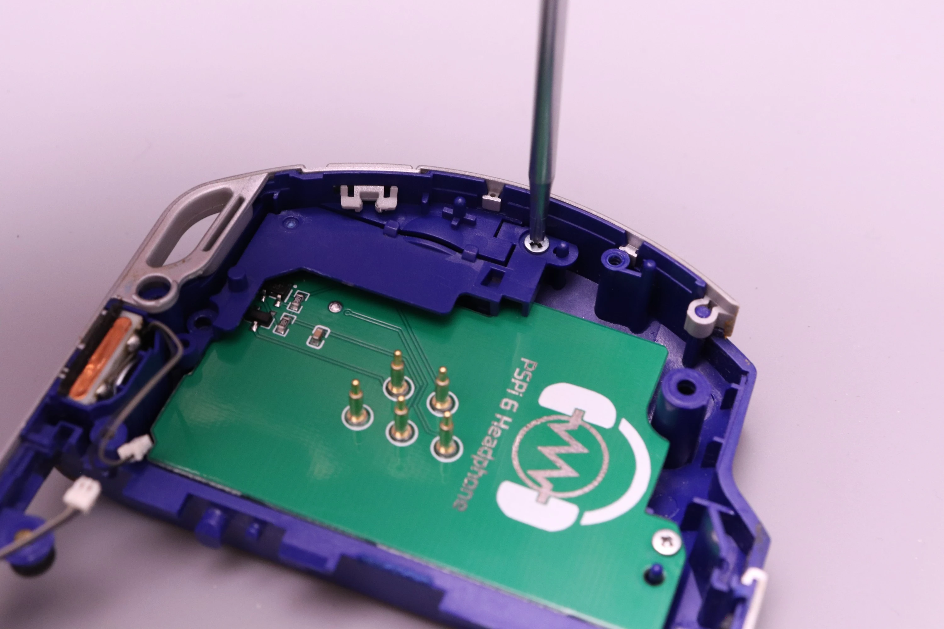
Start by setting the bottom side of the headphone board into position, aligning the headphone connector with the hole in the PSP shell. Then tilt it down and into position and install the top screw.
 |
 |
 |
 |
This next step is optional, but you can also install the bracket that was originally on the PSP headphone board to help guide the memory card into place. It doesn't serve anything other than a cosmetic purpose here.
 |
 |
 |
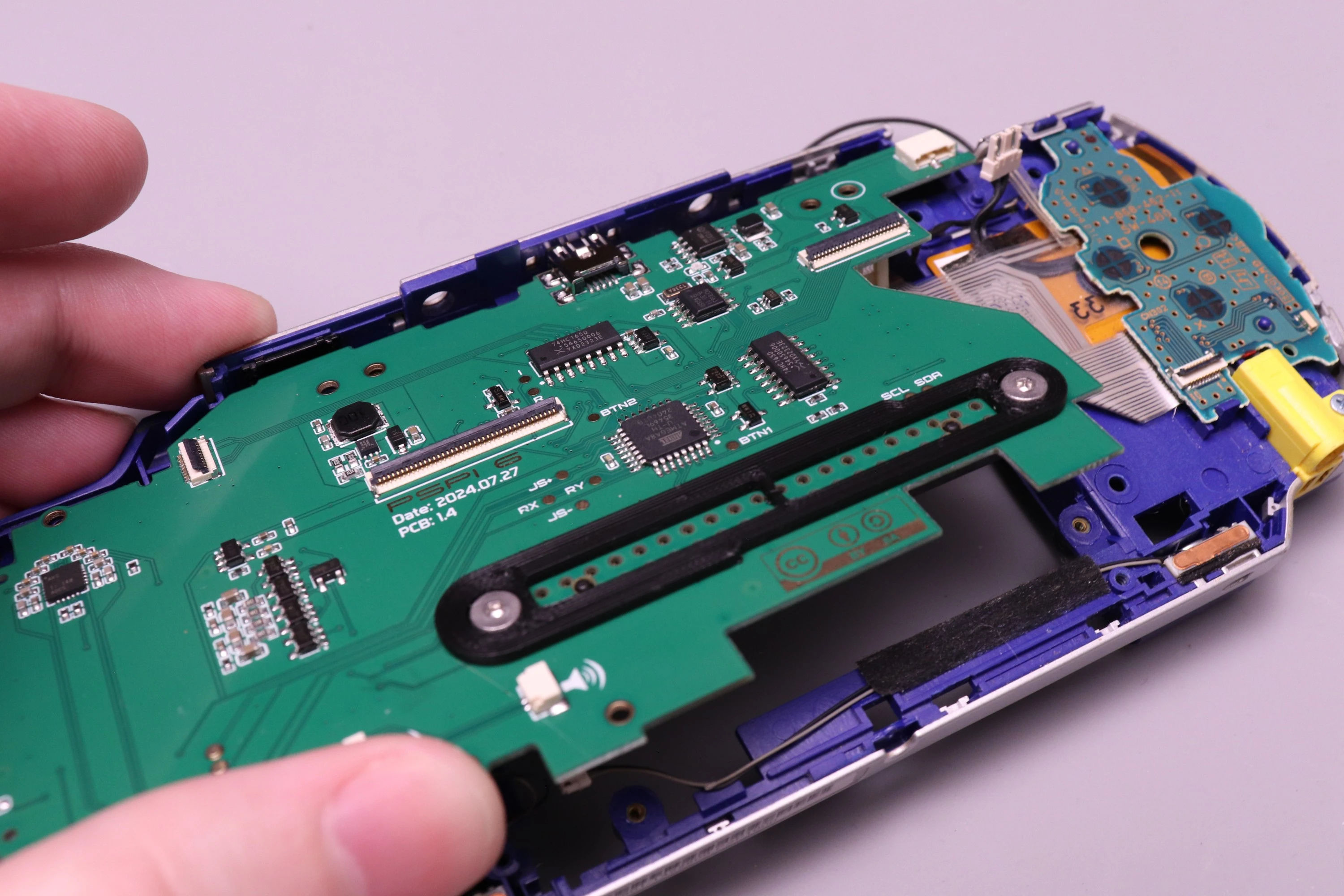
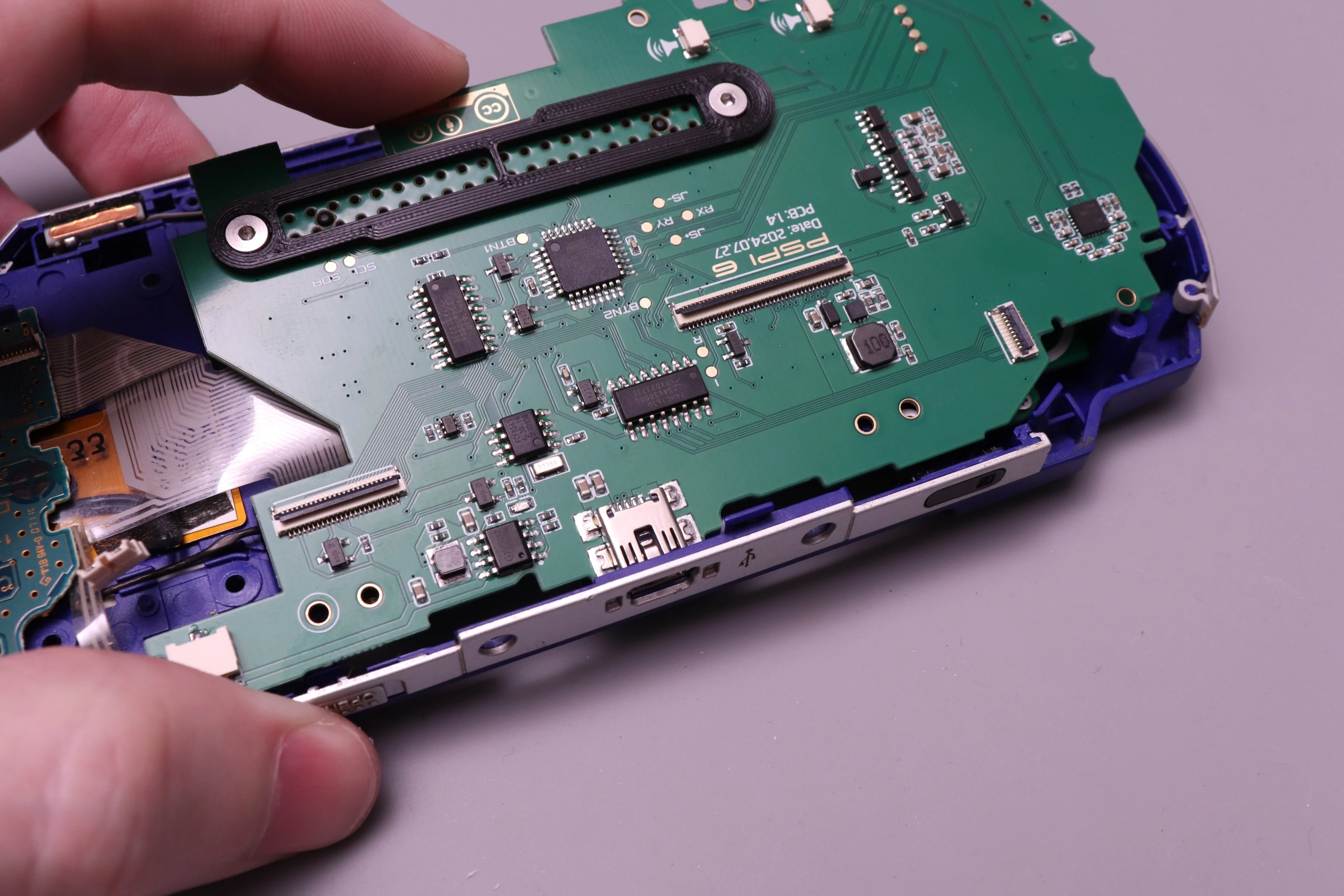
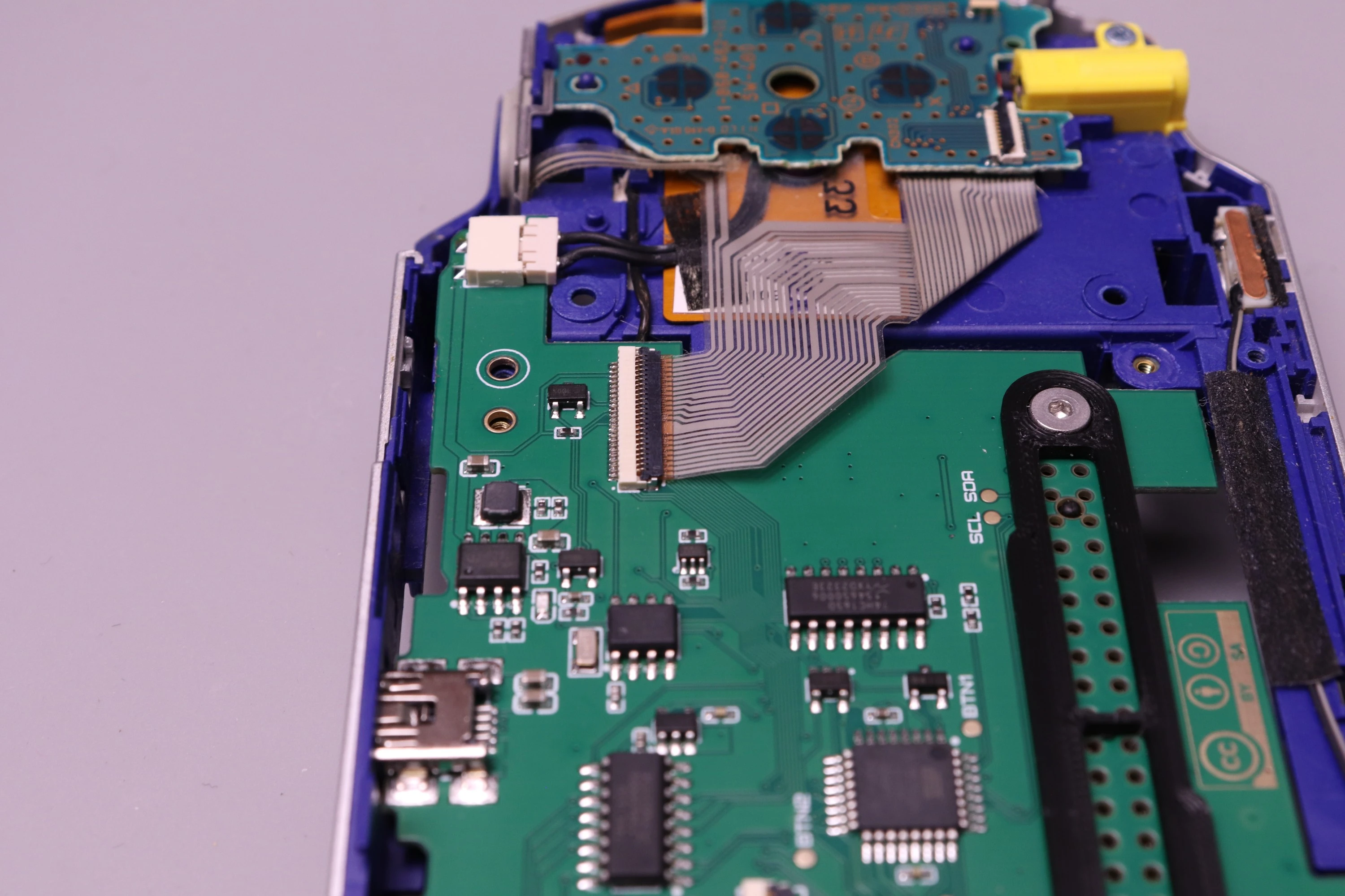
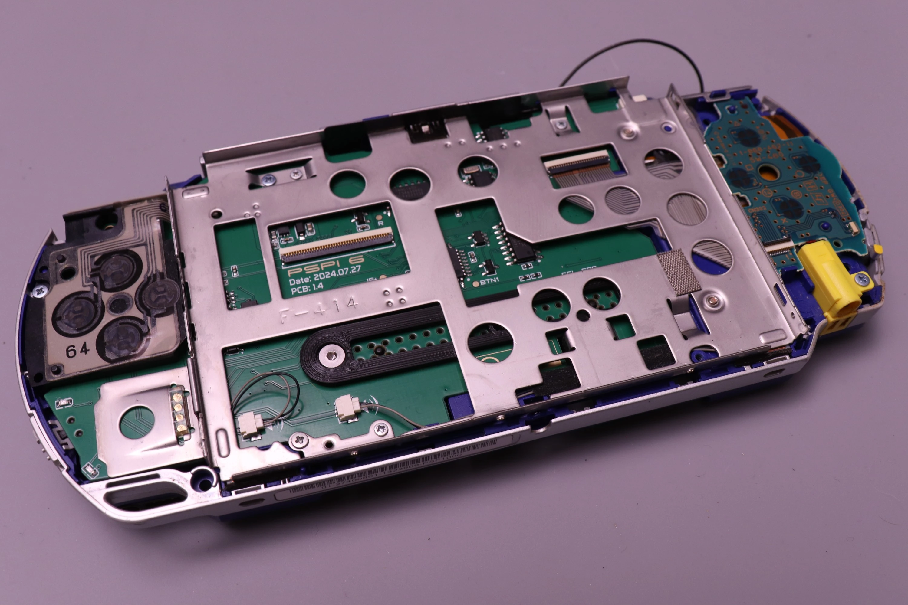
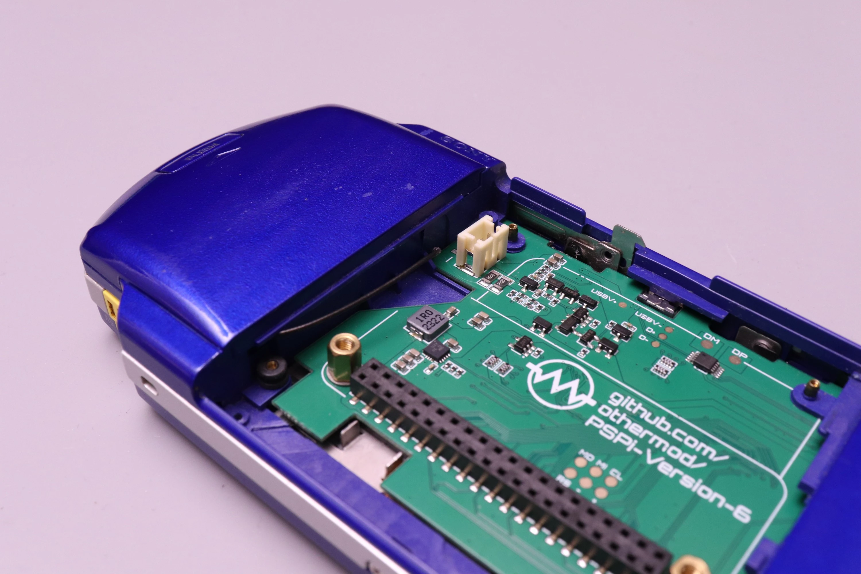
Place the mainboard into the shell, focusing on the positioning of the USB connector first. Set the USB connector into the hole on the case, and then prepare to tilt the board down and into position.
 |
 |
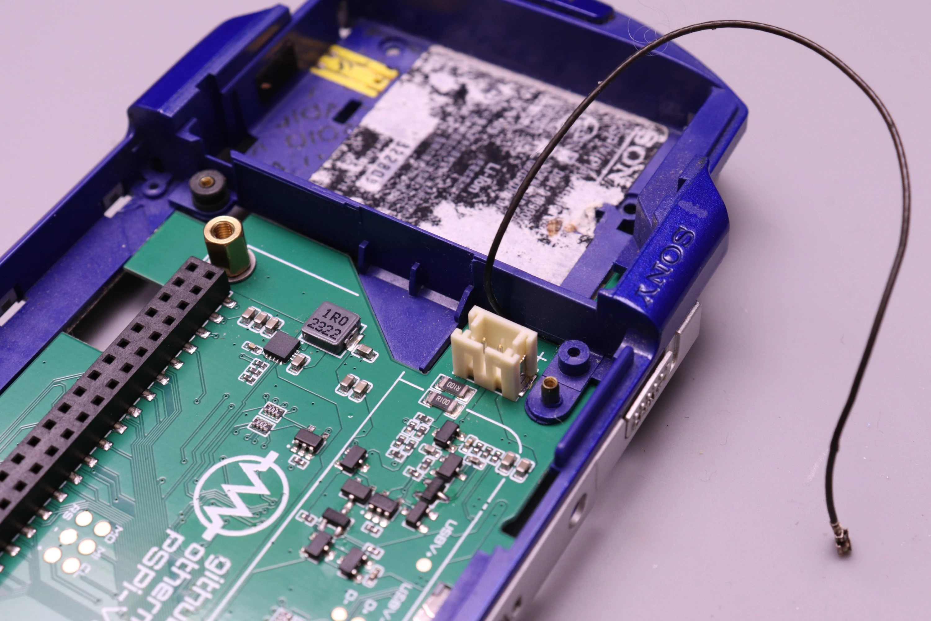
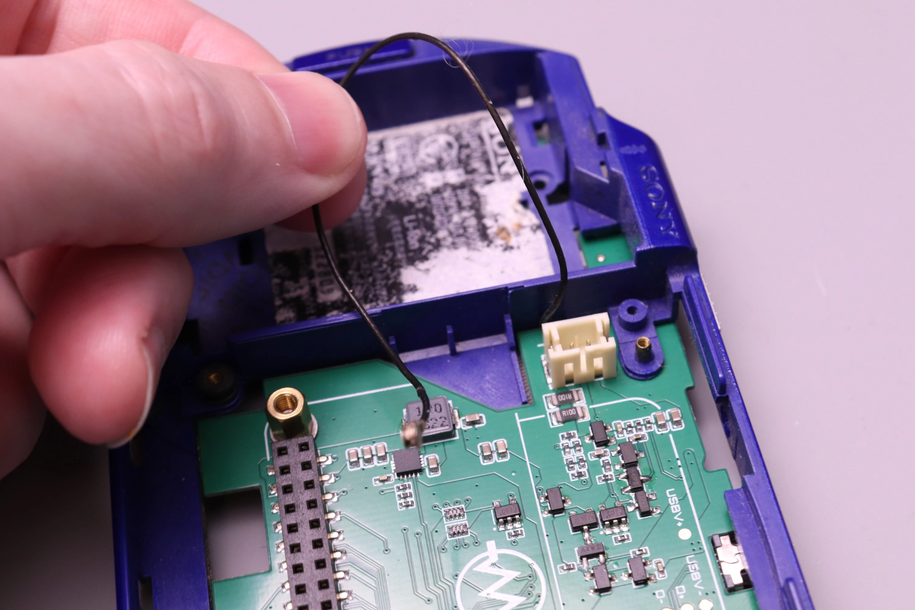
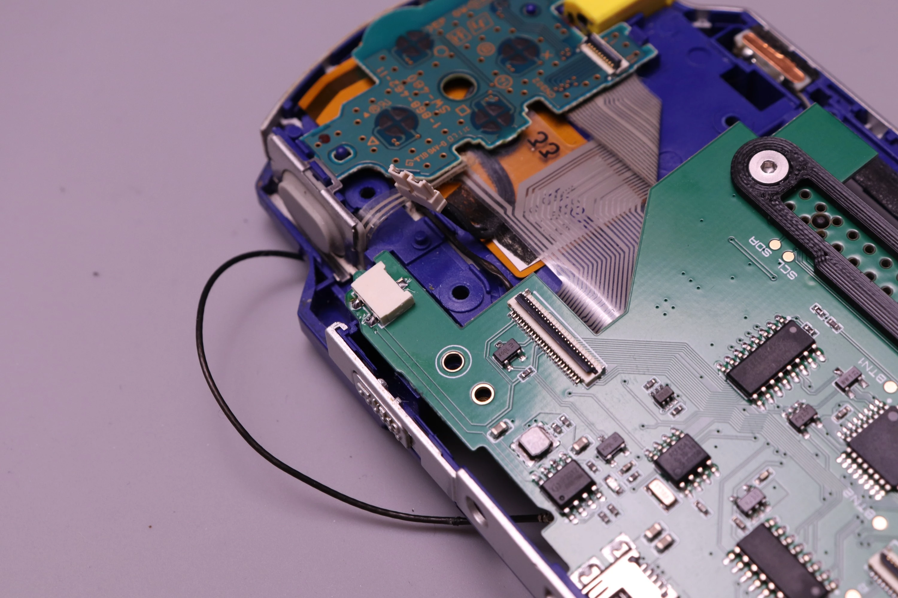
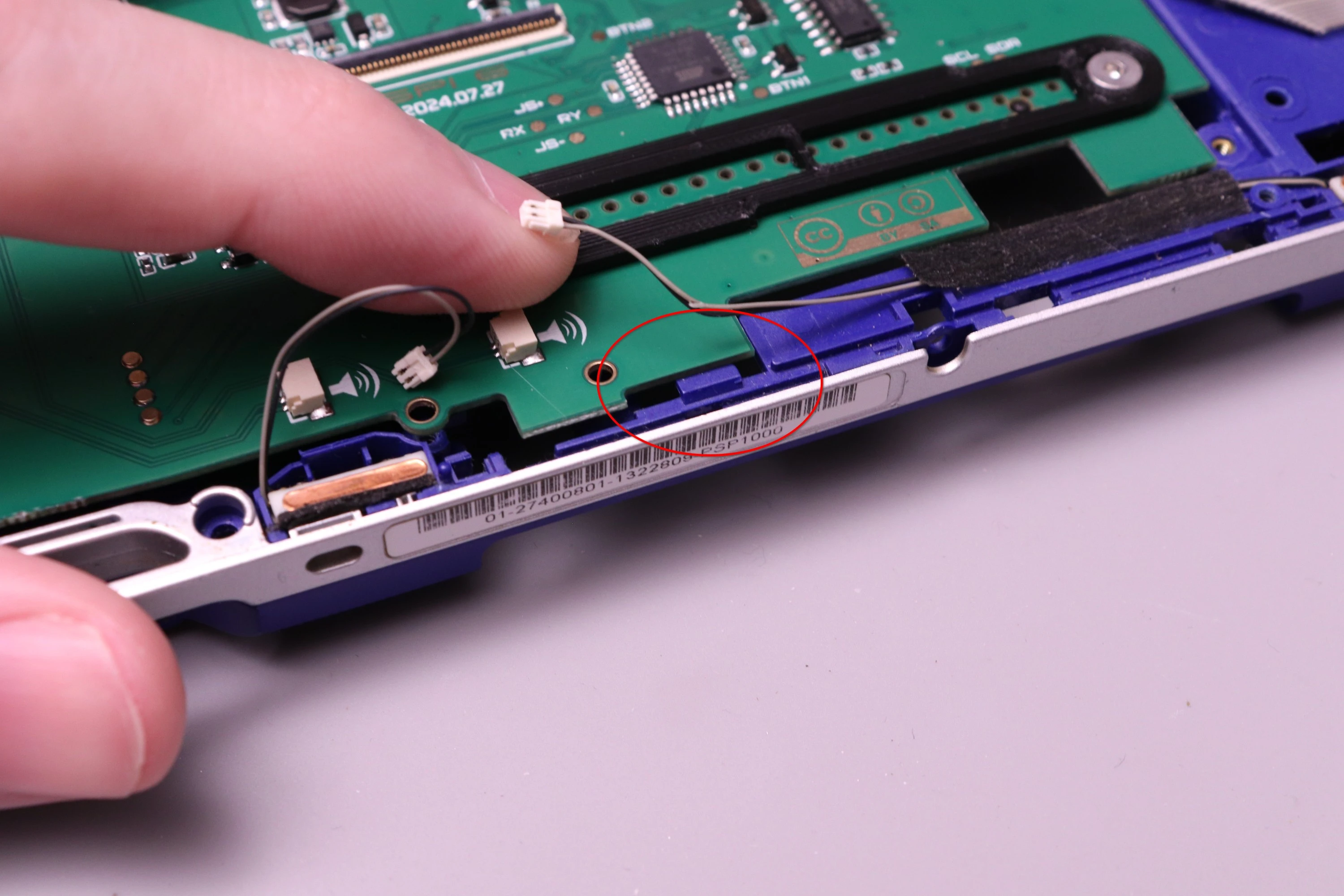
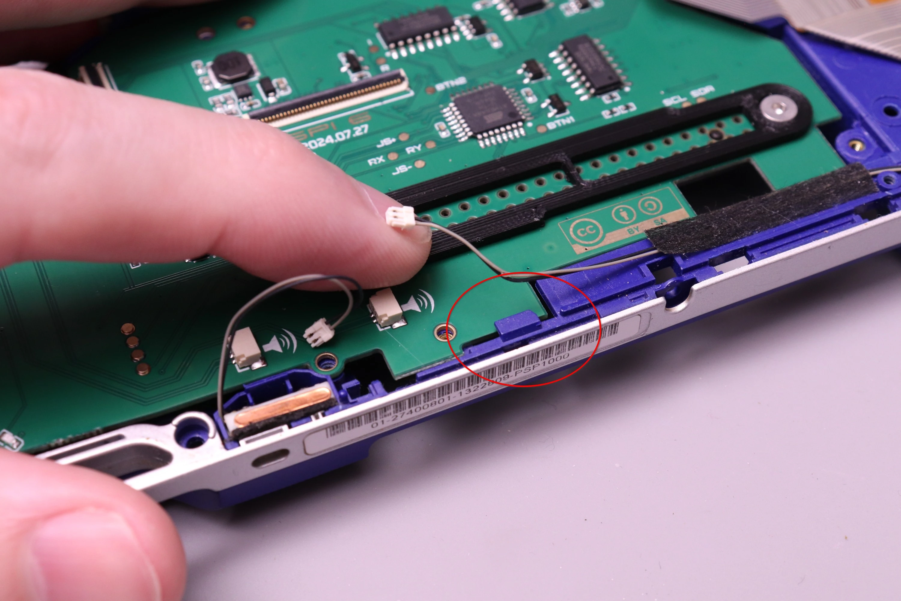
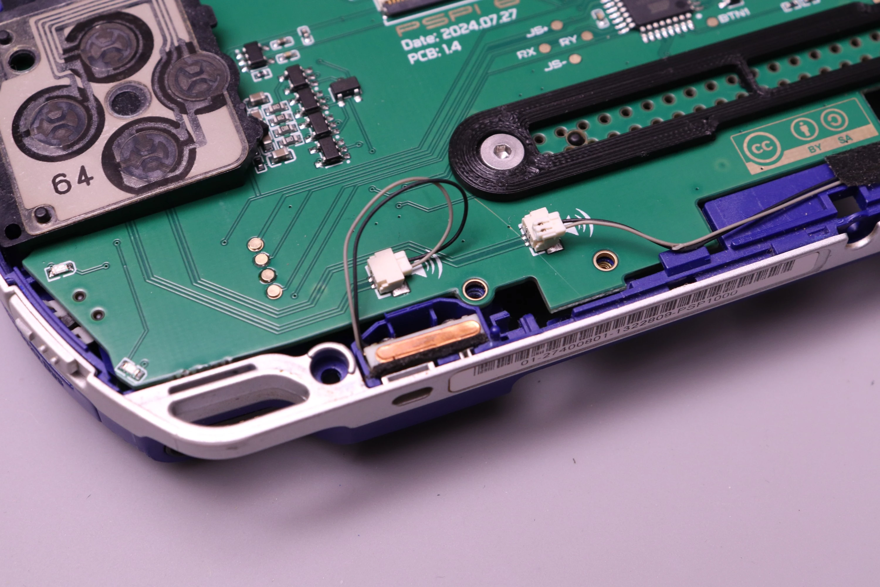
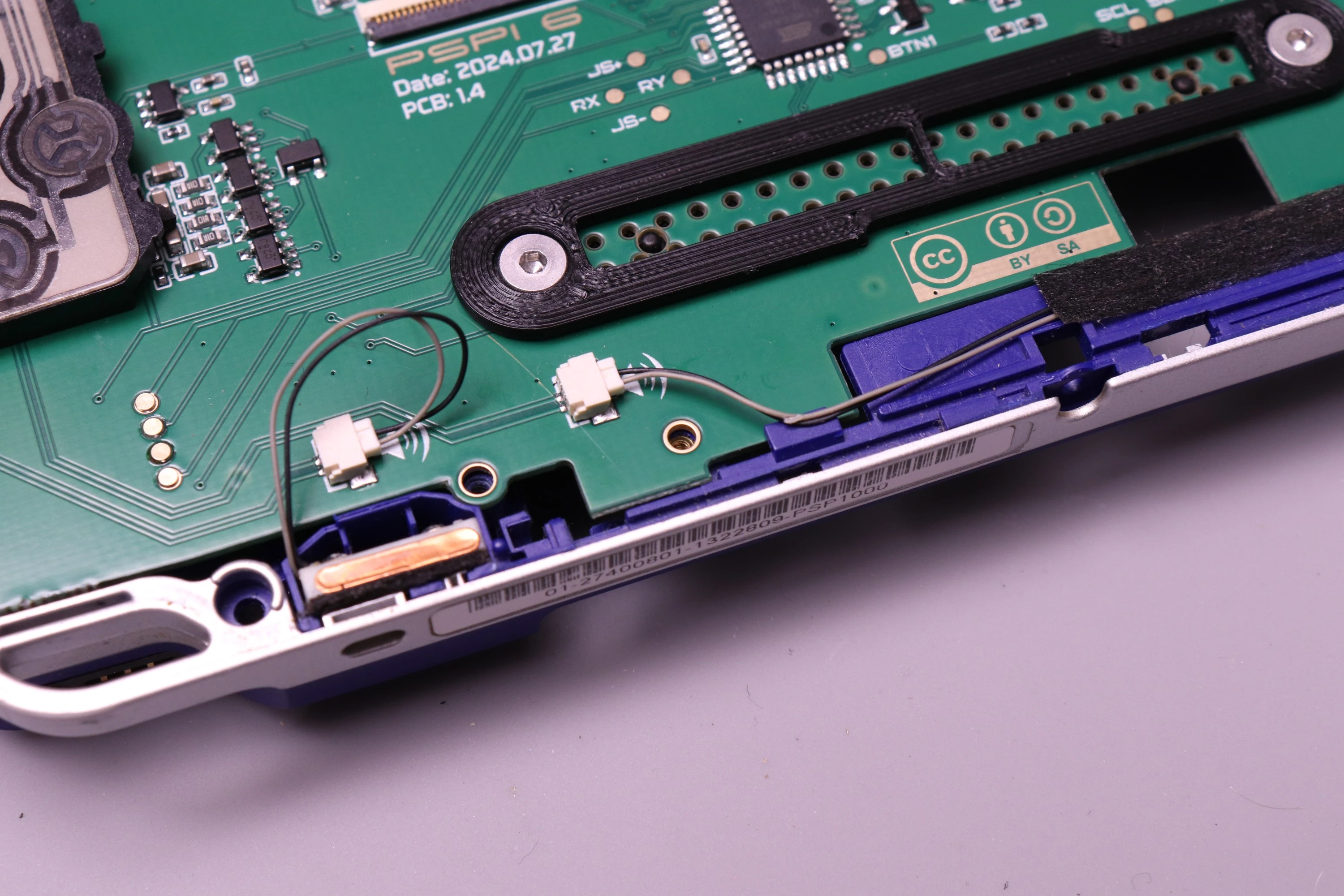
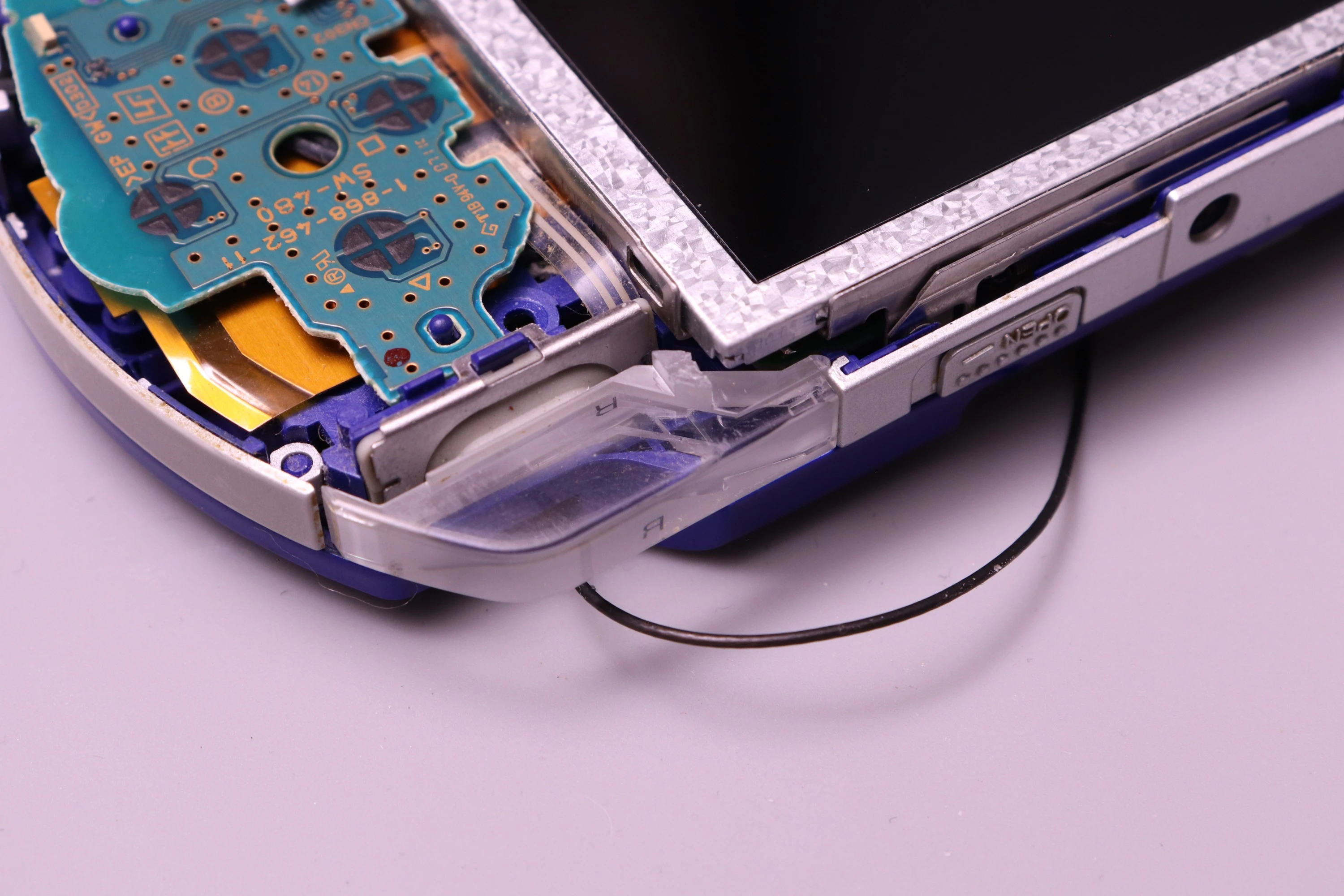
Then verify that the WiFi antenna cable is routed to the UMD bay.
 |
 |
Then verify that the barrel jack cable, FPC-24 cable, and headphone cables aren't wedged under the board.
| Barrel Jack Cable | FPC-24 Cable | Speaker Wires |
|---|---|---|
 |
 |
 |
Now you can tilt the board down and prepare to install screws. When pushing the board down, you can use this plastic protrusion to lock the board in place. Just flex the plastic outward a slight amount, push the board down, and release the force on the plastic so it bends back into place. Some earlier PSP shells don't have this.
 |
 |
The PSPi 6 will flex a tiny bit at the USB connector, and this is expected.
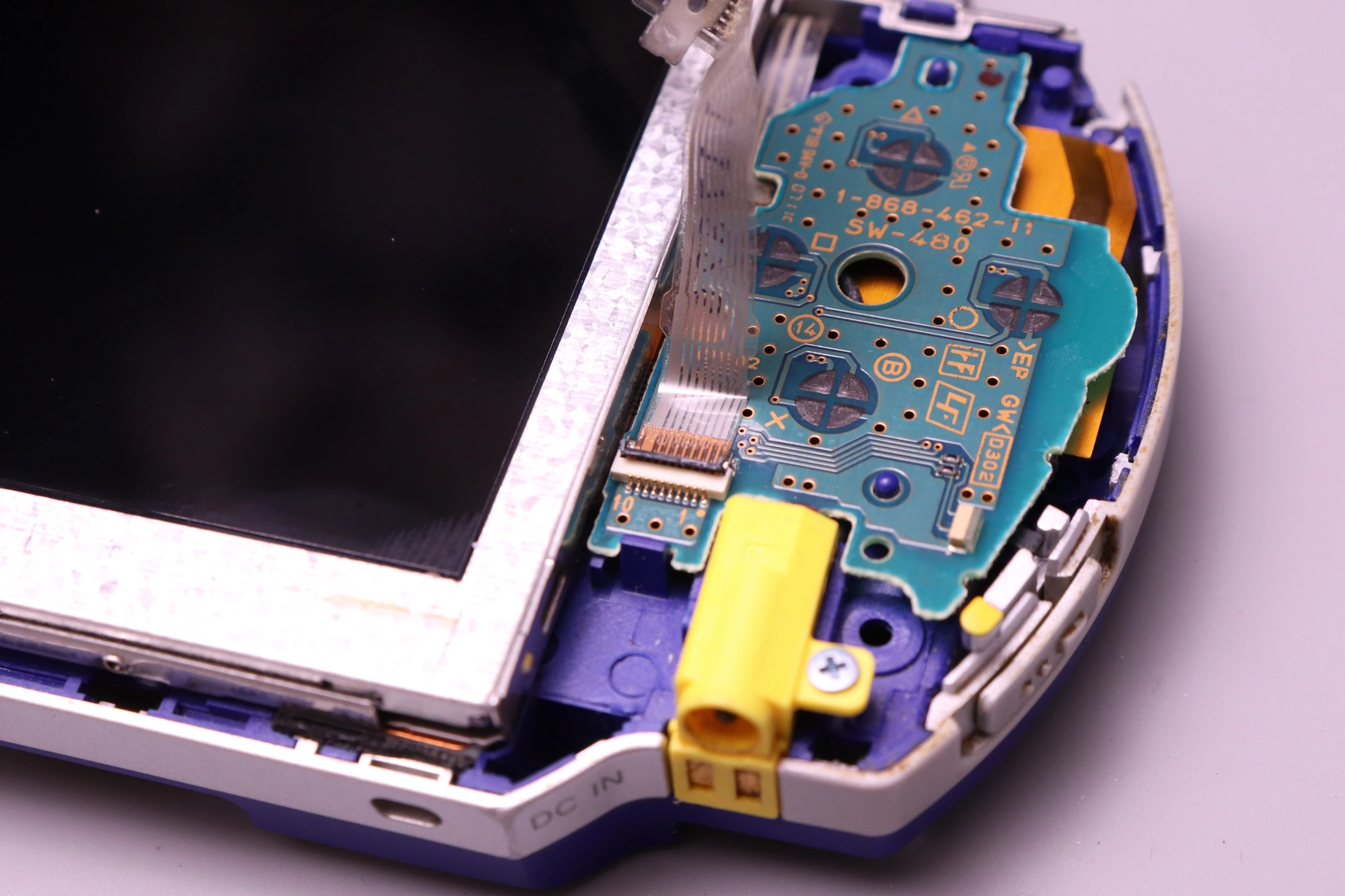
Now let's attach the barrel jack connector.
 |
 |
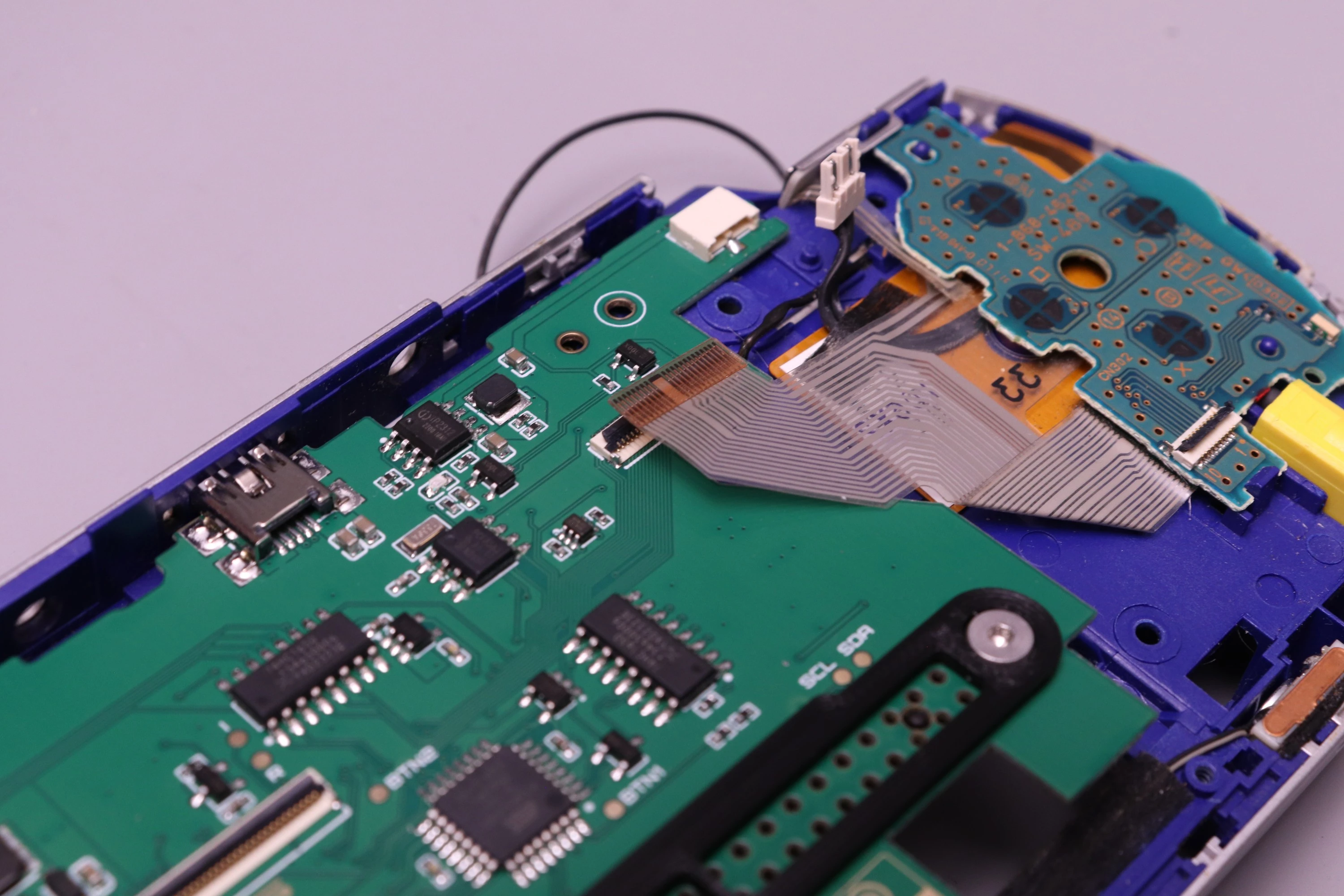
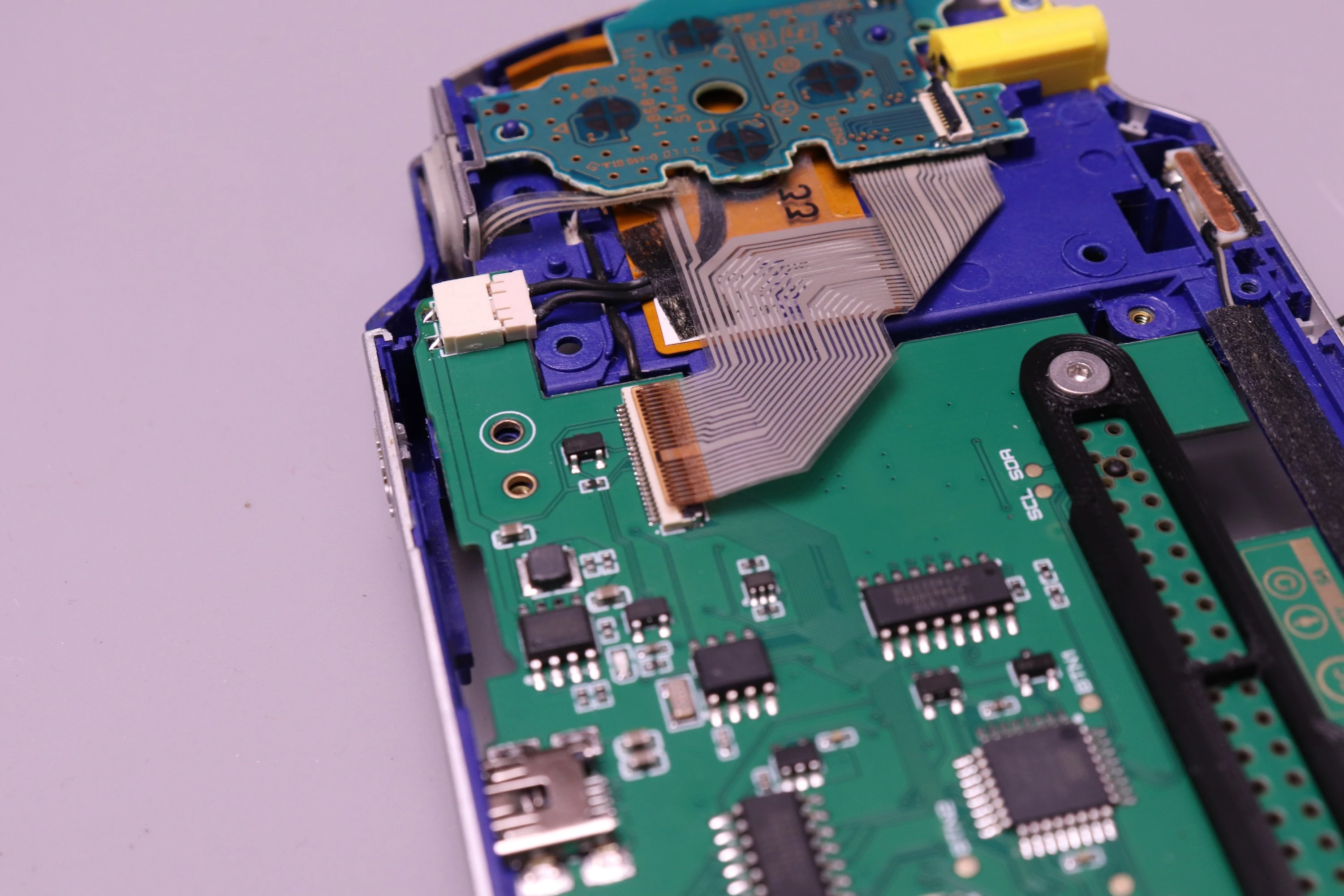
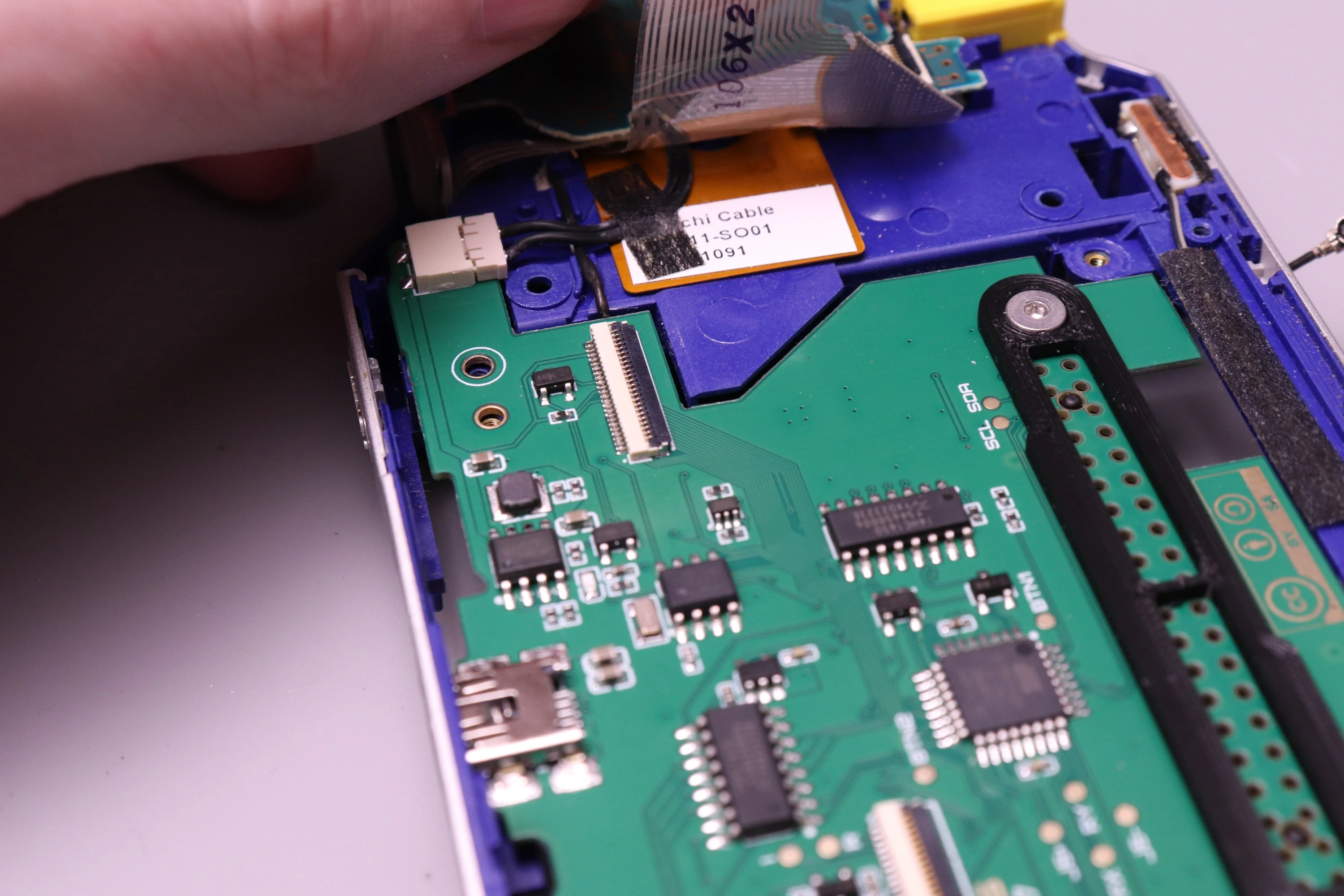
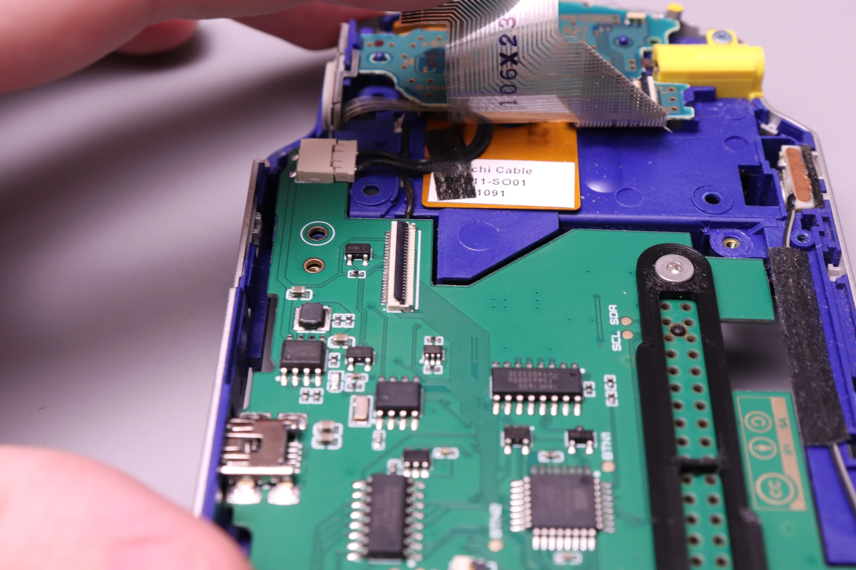
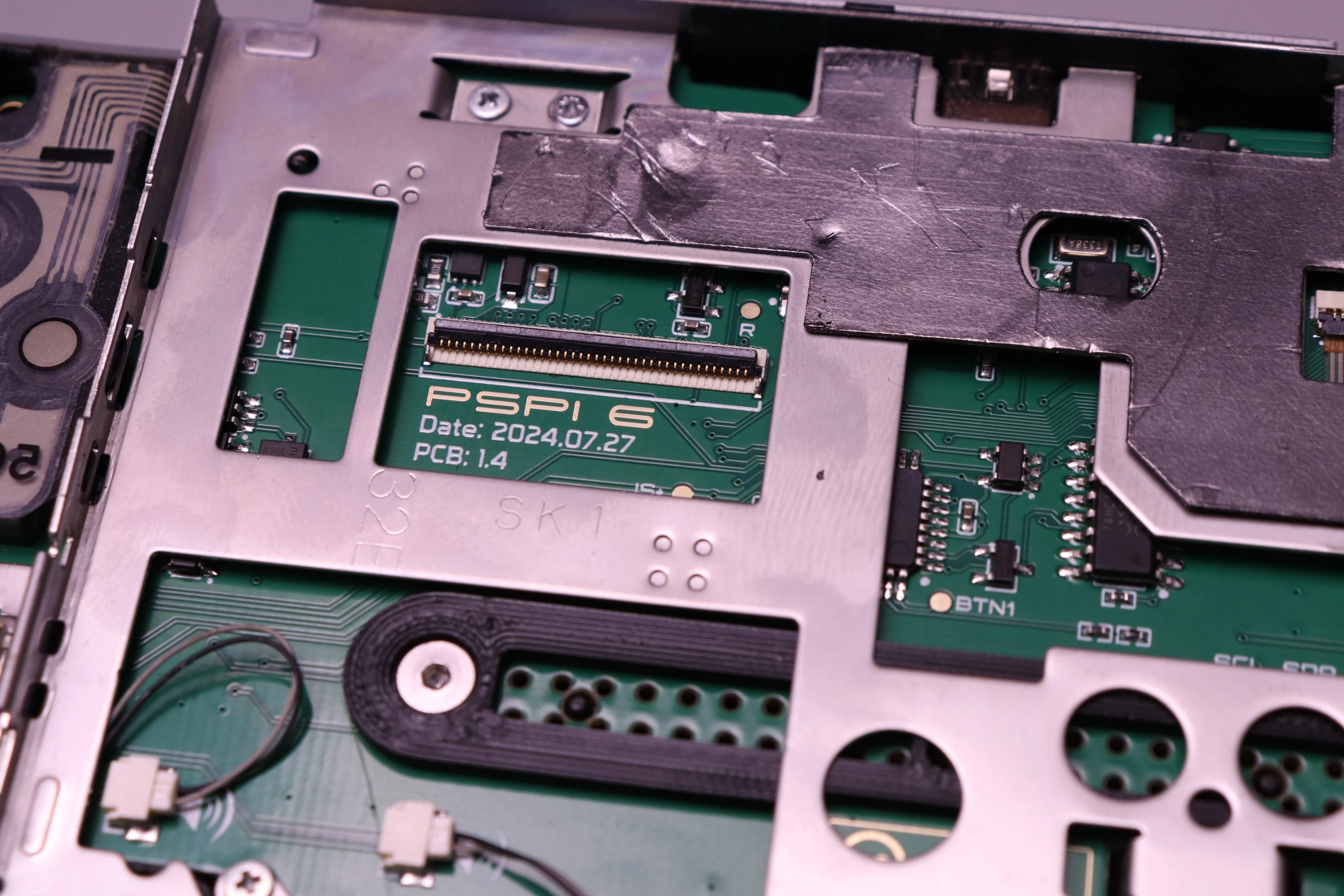
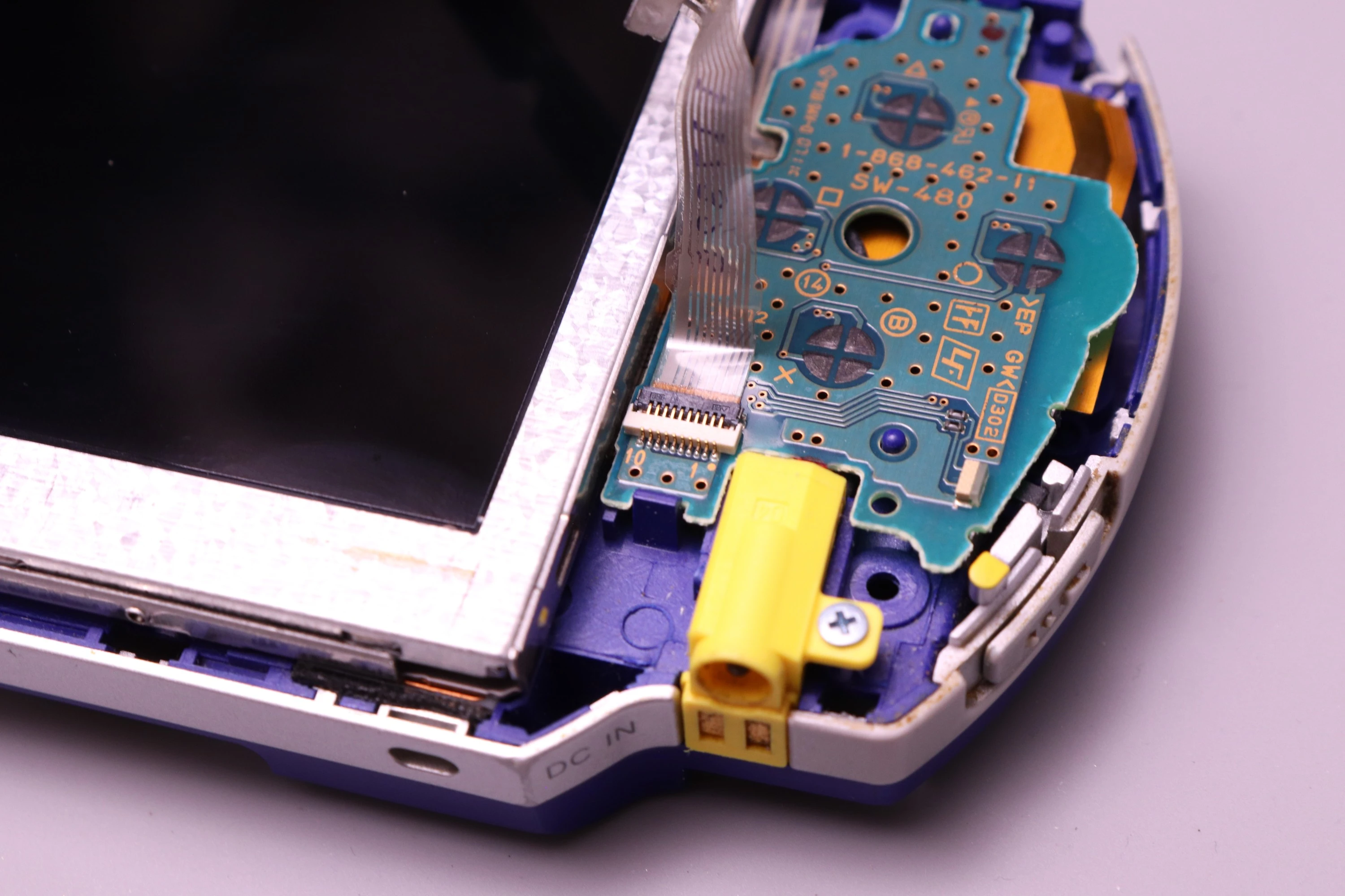
Now install the FPC-24 cable. Start by lifting the cable out of the way so you can look at the connector. It has a latch on top that must first be lifted.
| Lift the Cable | View the FPC | Lift the Latch |
|---|---|---|
 |
 |
 |
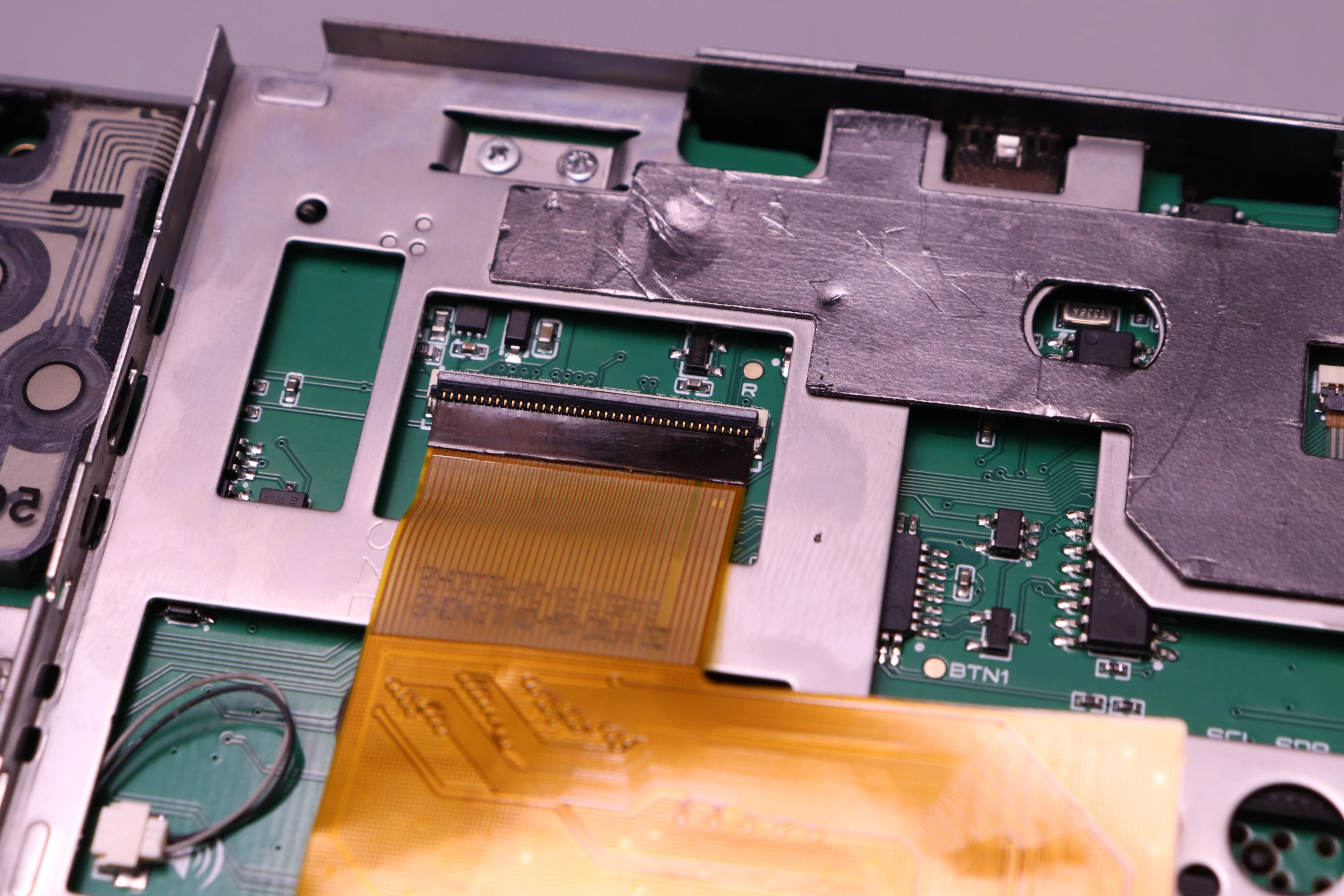
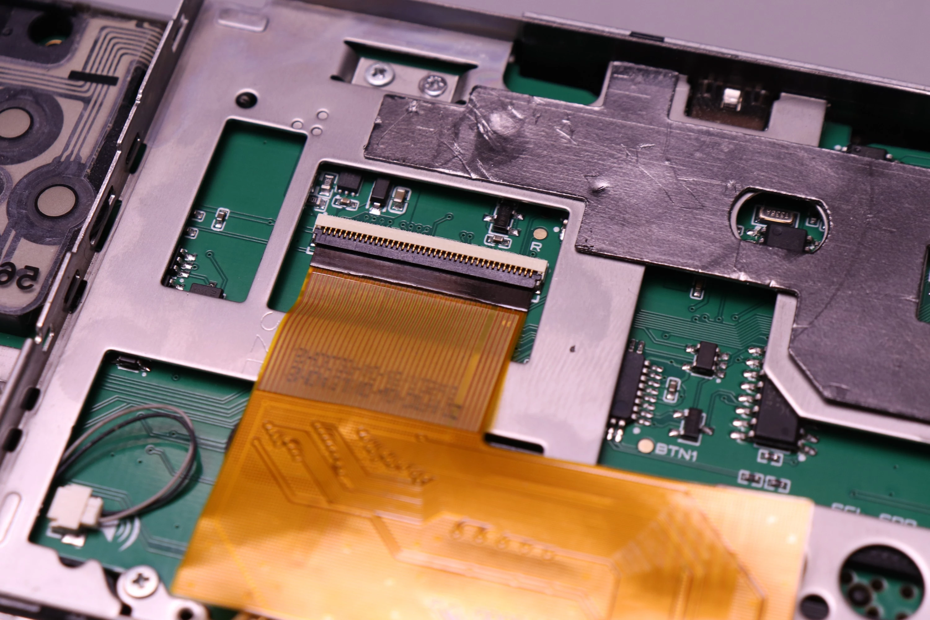
Then install the FPC-24 cable and latch the connector closed.
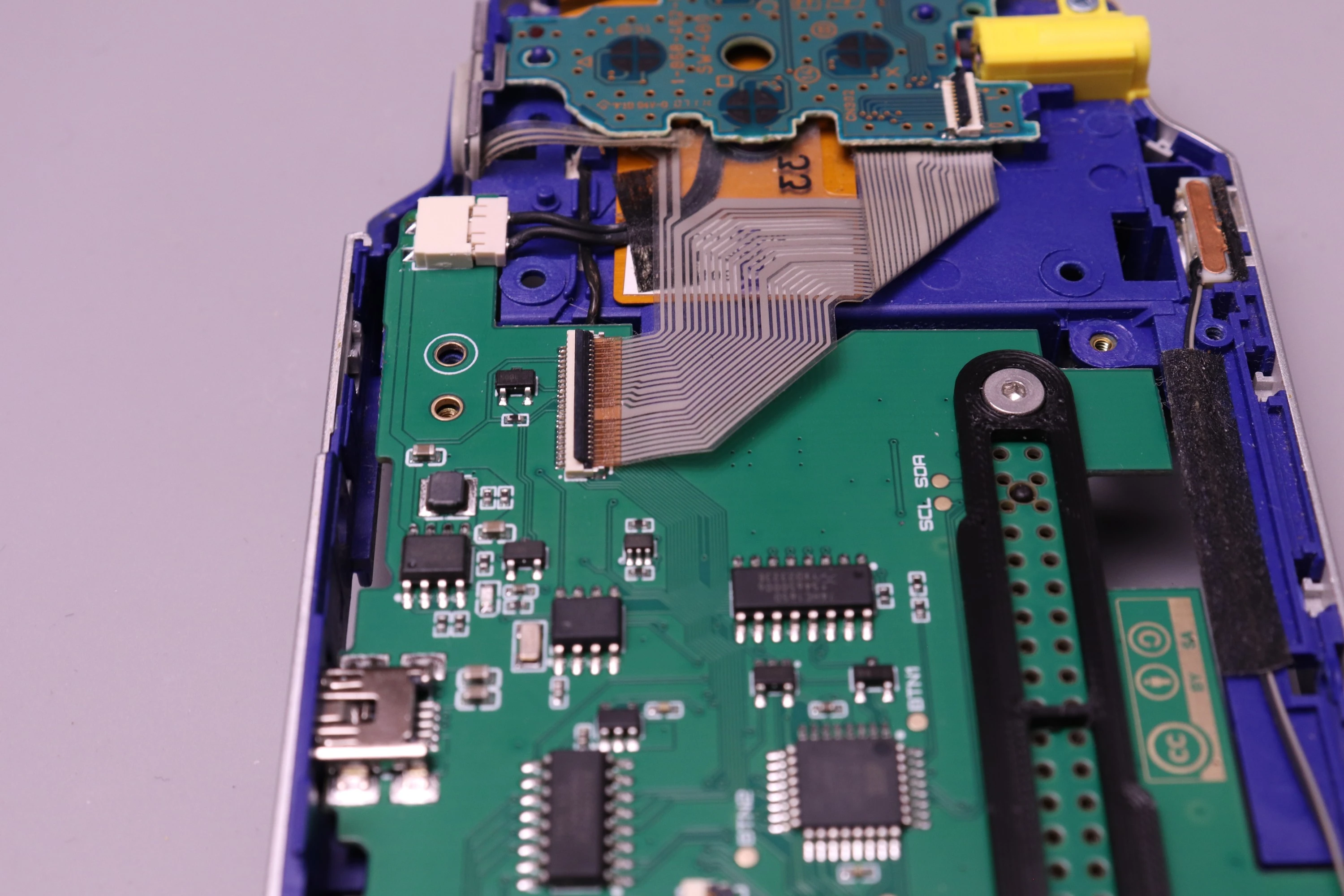 |
 |
The FPC-10 mechanism is the same as the FPC-24, so you'll need to lift the retainer, insert the cable all the way in, and then press down to secure it in place.
 |
 |
 |
Make sure the cable is fully seated and the retainer is pressed down firmly to ensure a good connection.
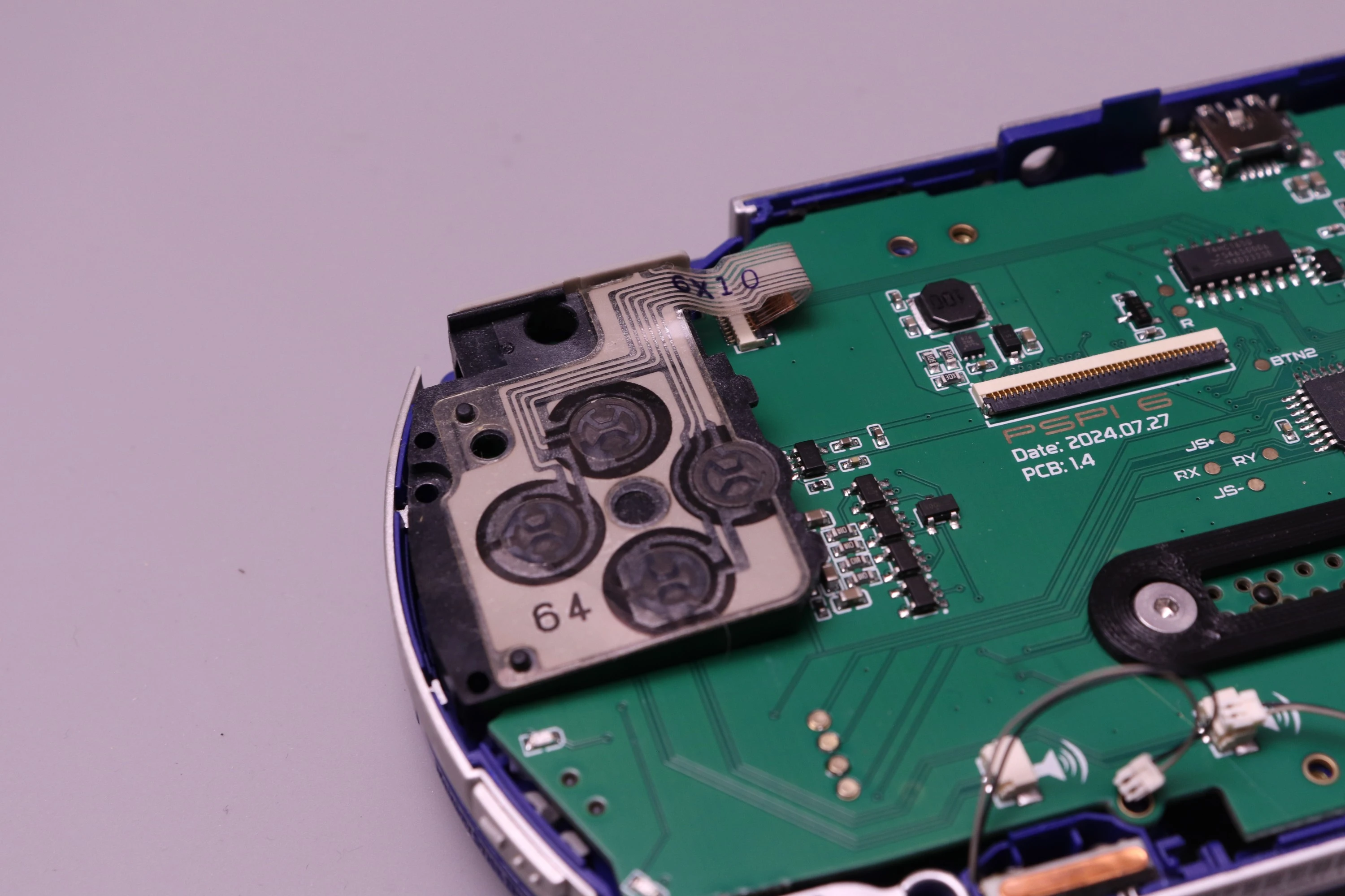
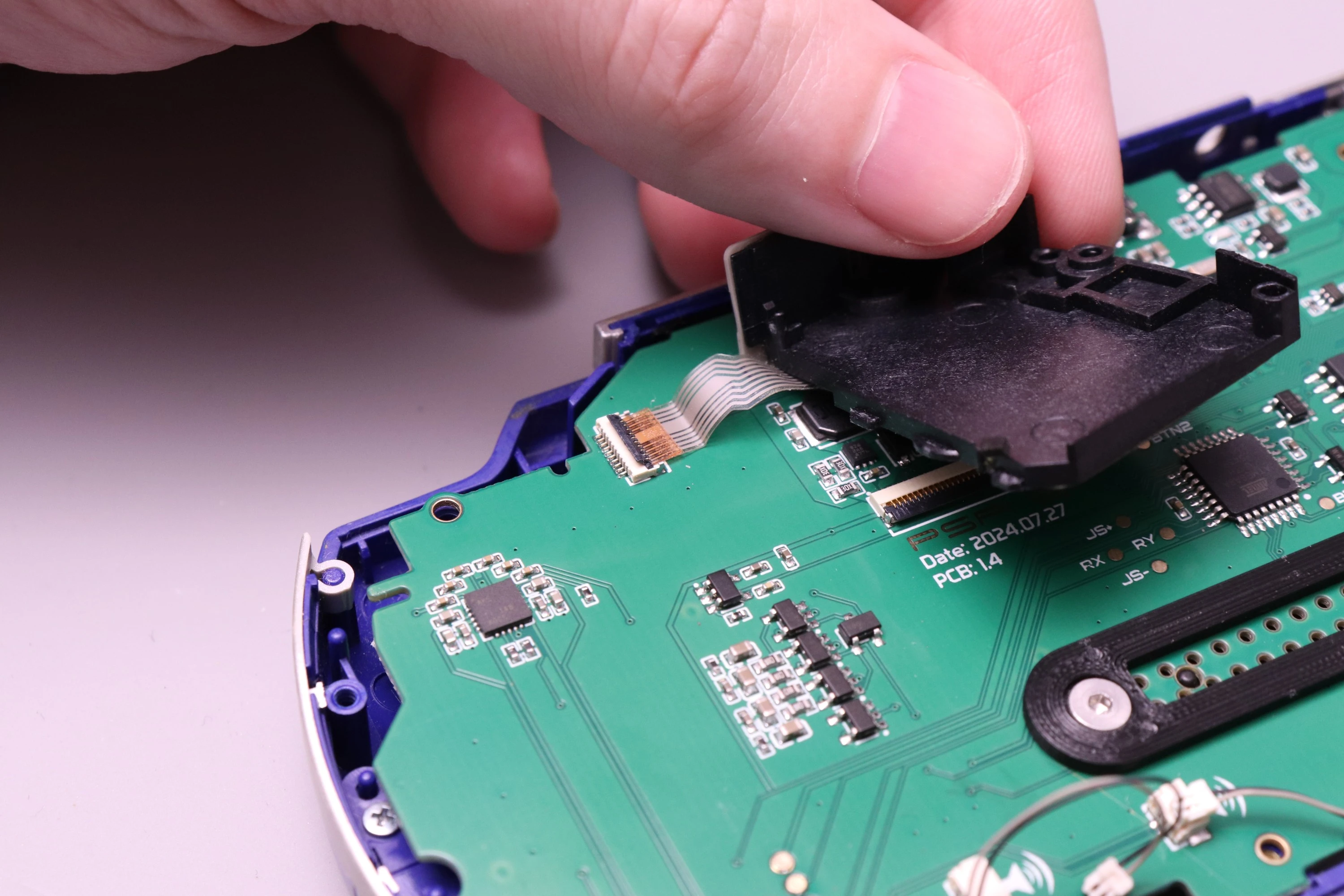
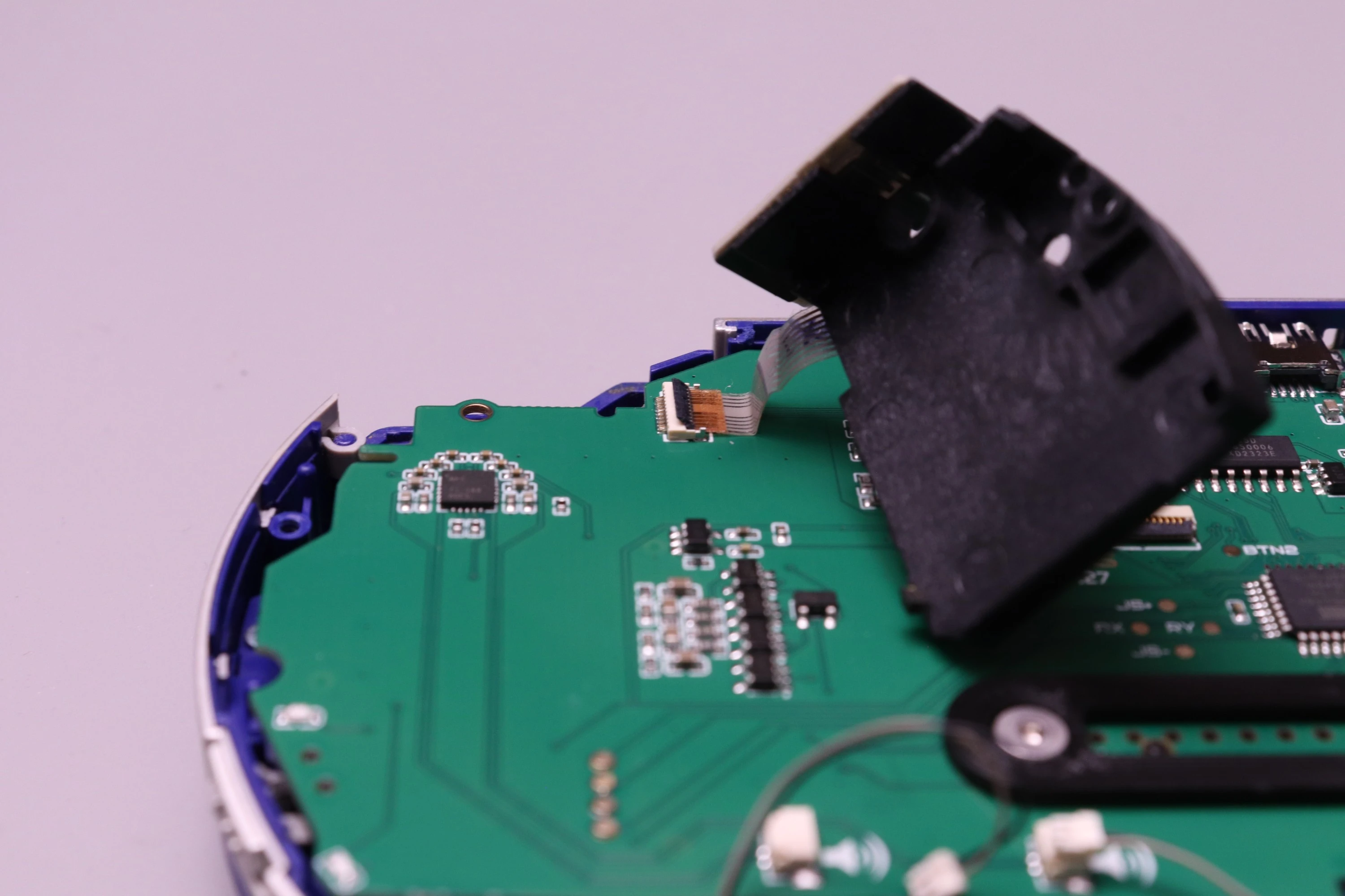
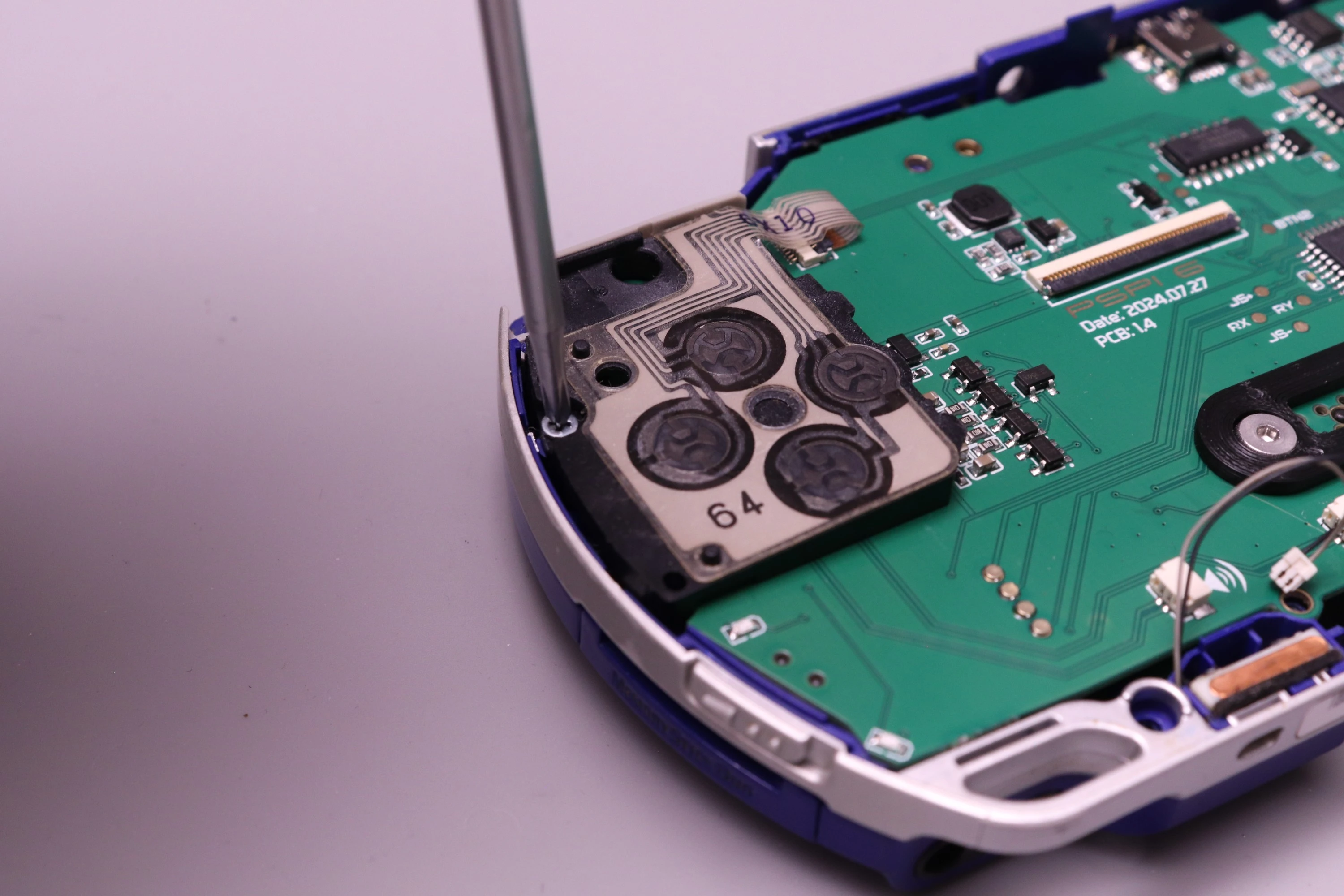
Install one screw into the D-Pad. This is a silver screw with rough thread.
 |
 |
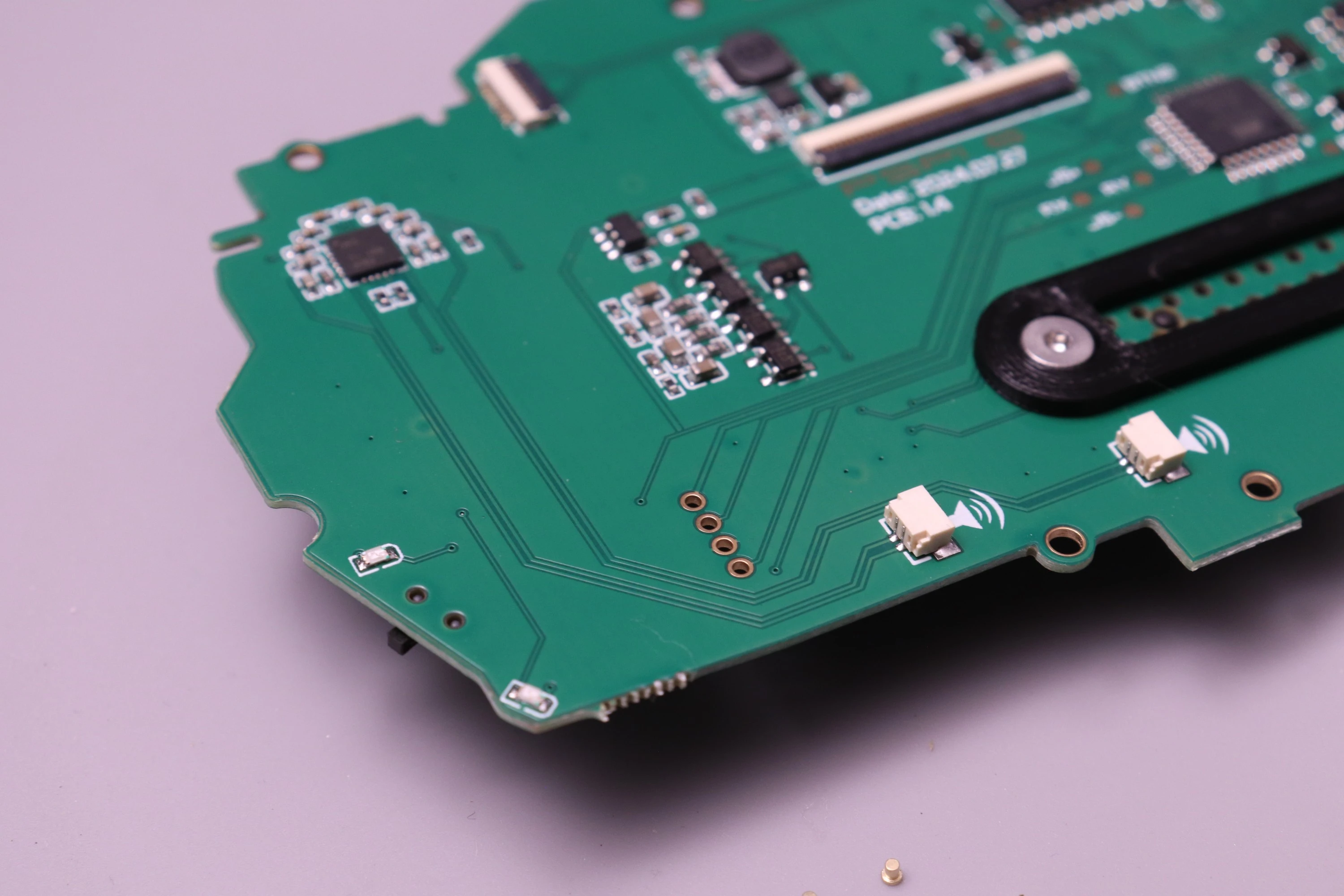
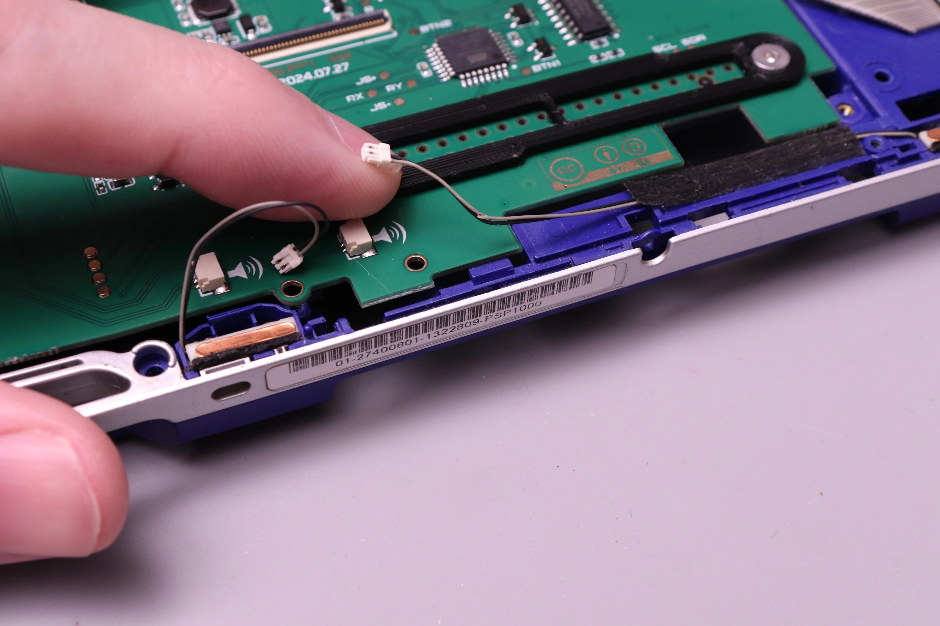
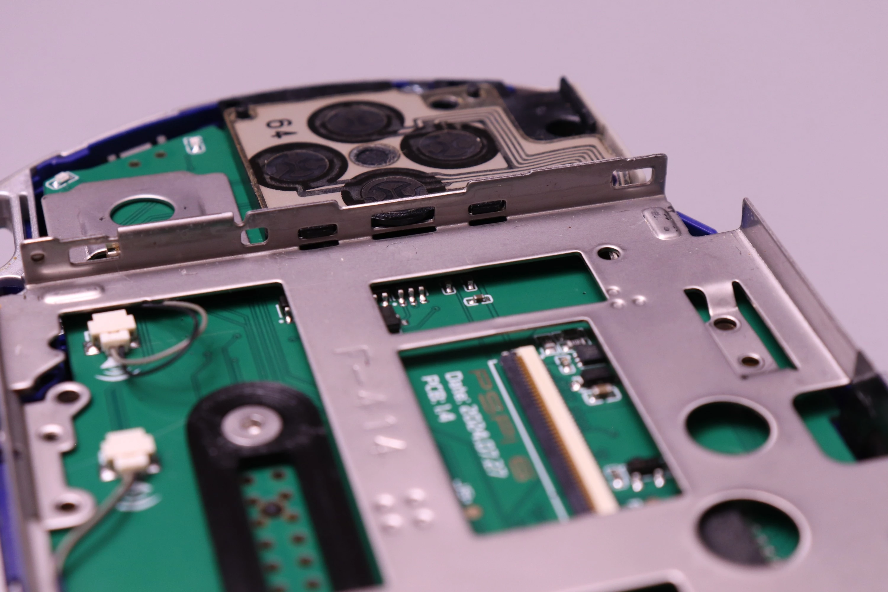
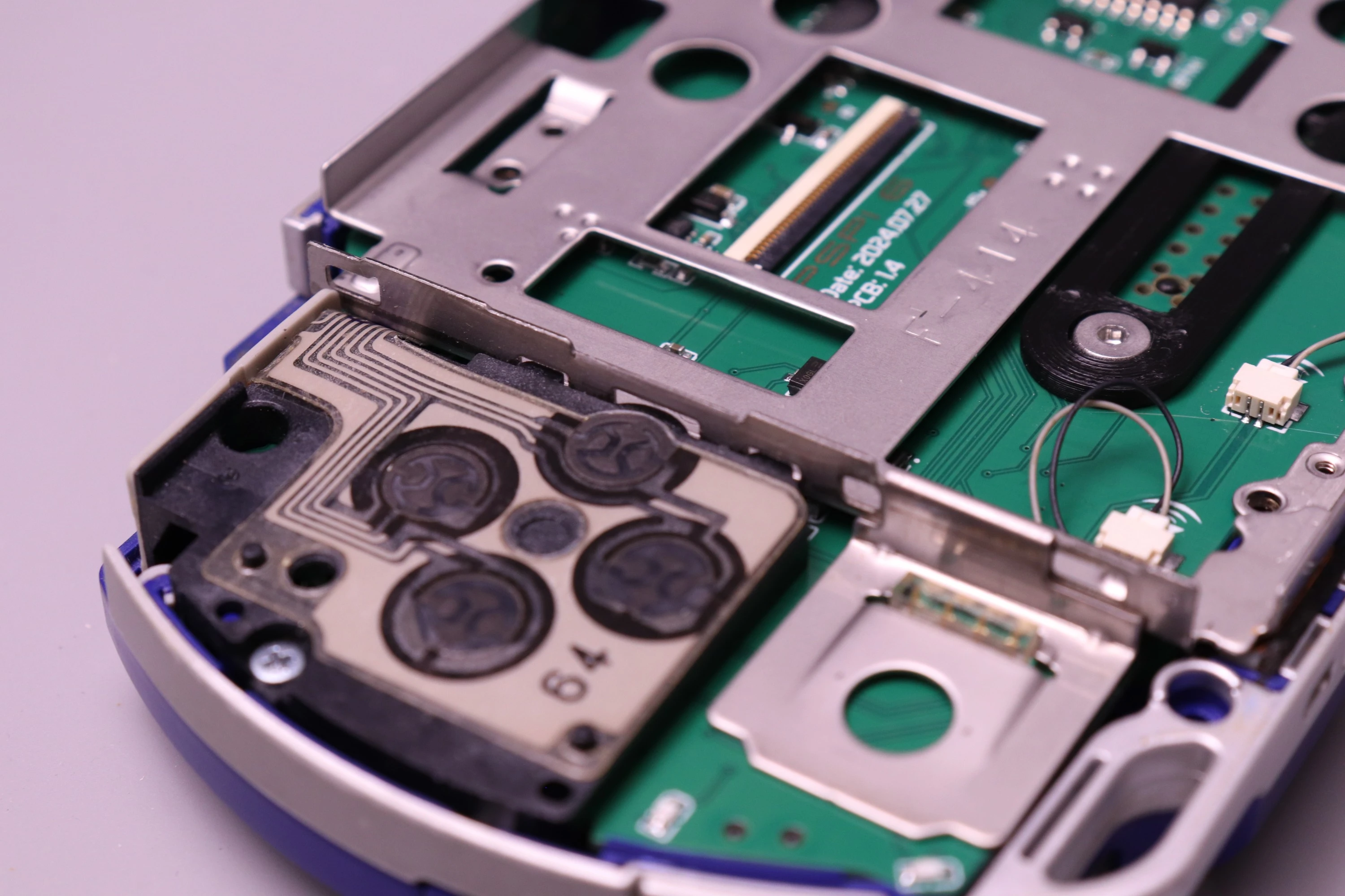
Connect the speaker wires to the mainboard. They attach exactly as they did on the original PSP board. Slide each into the connector that's closest to it.
 |
 |
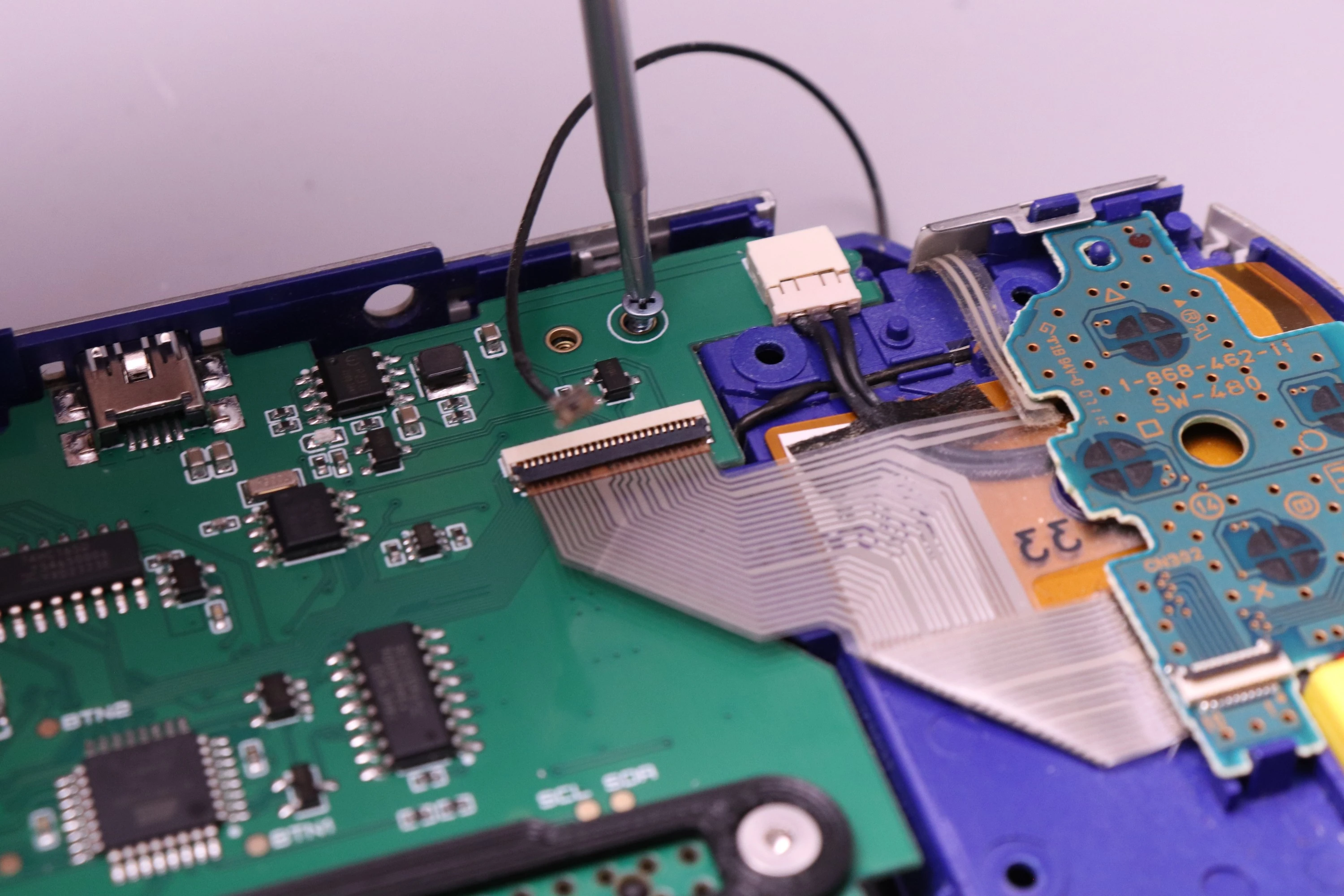
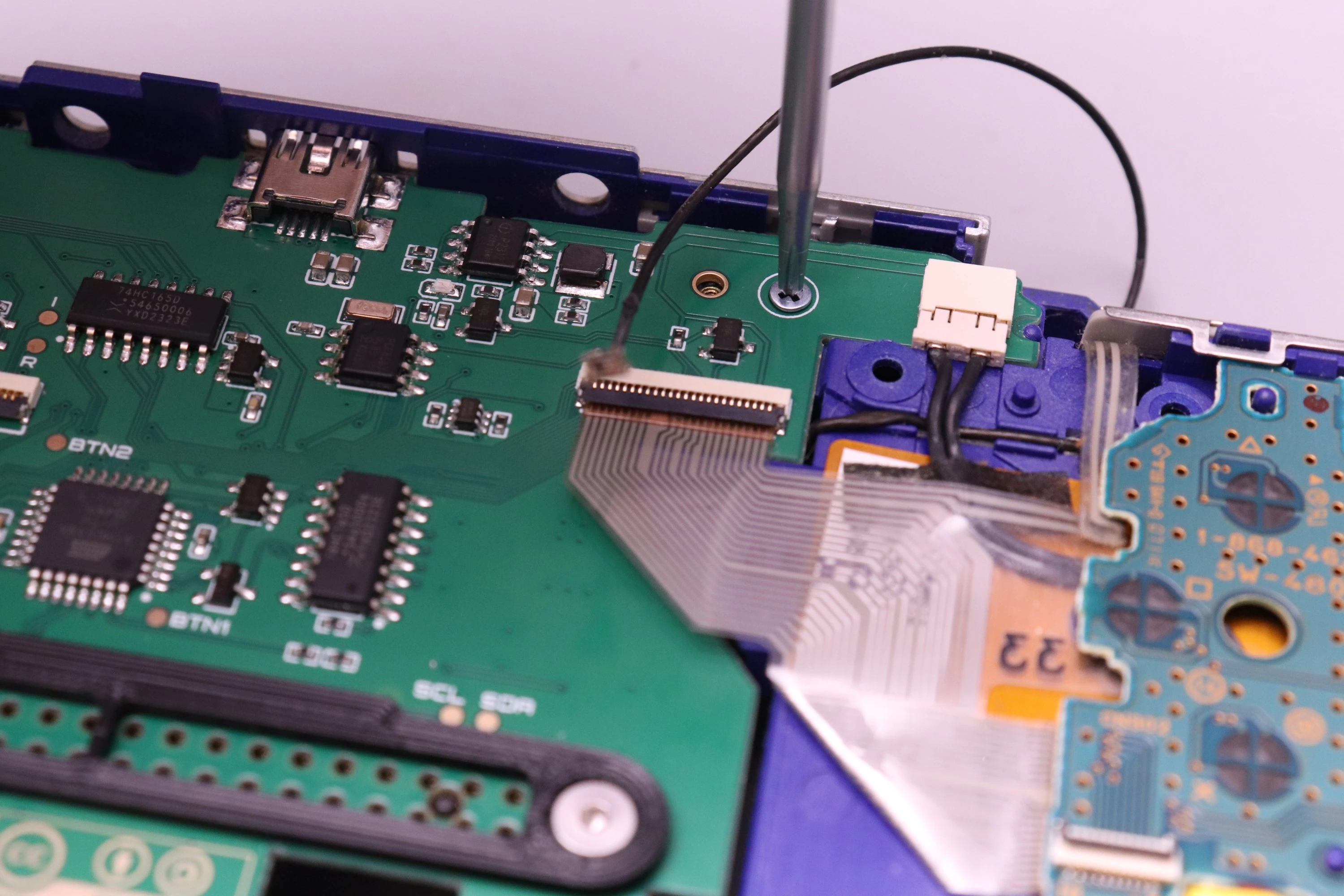
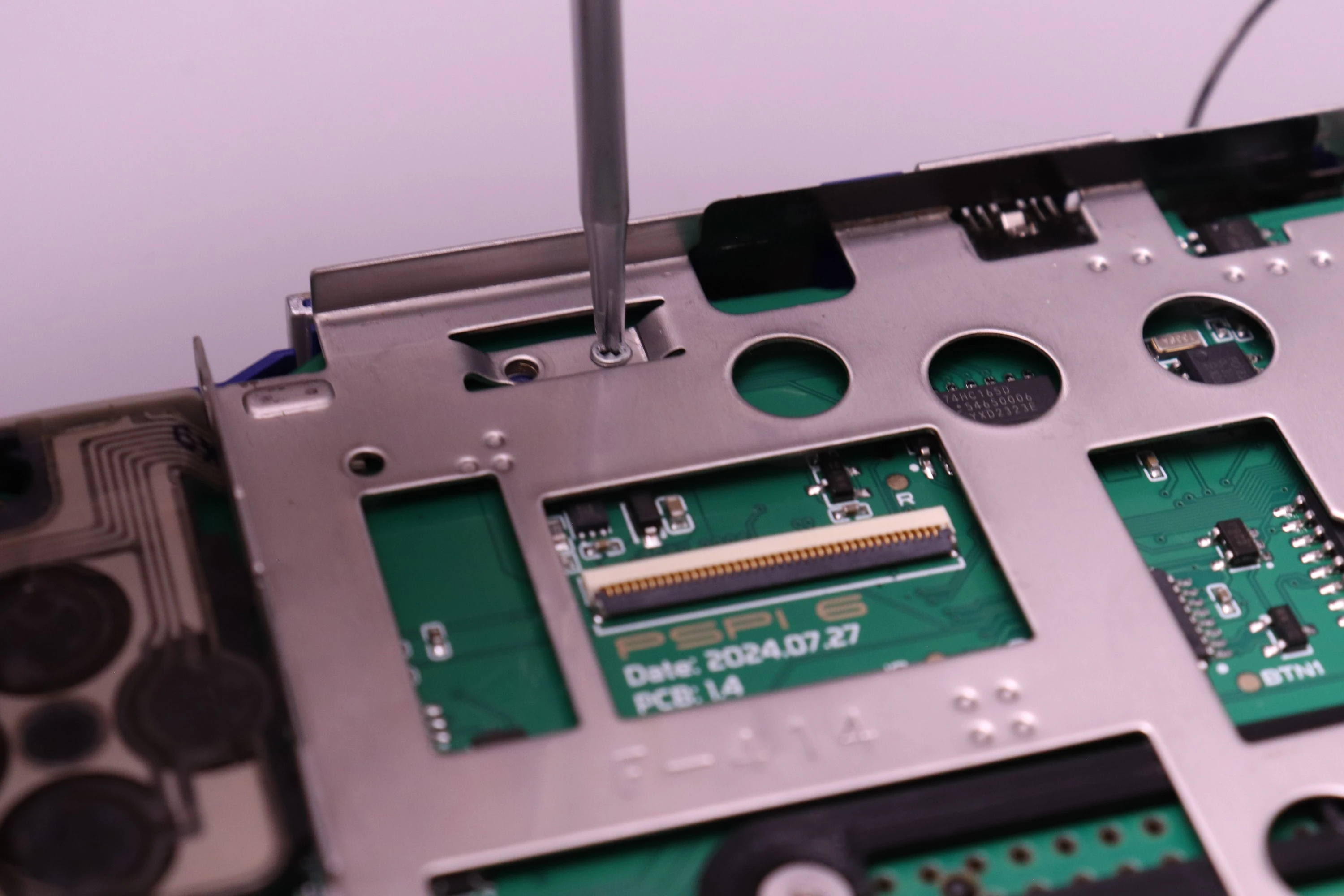
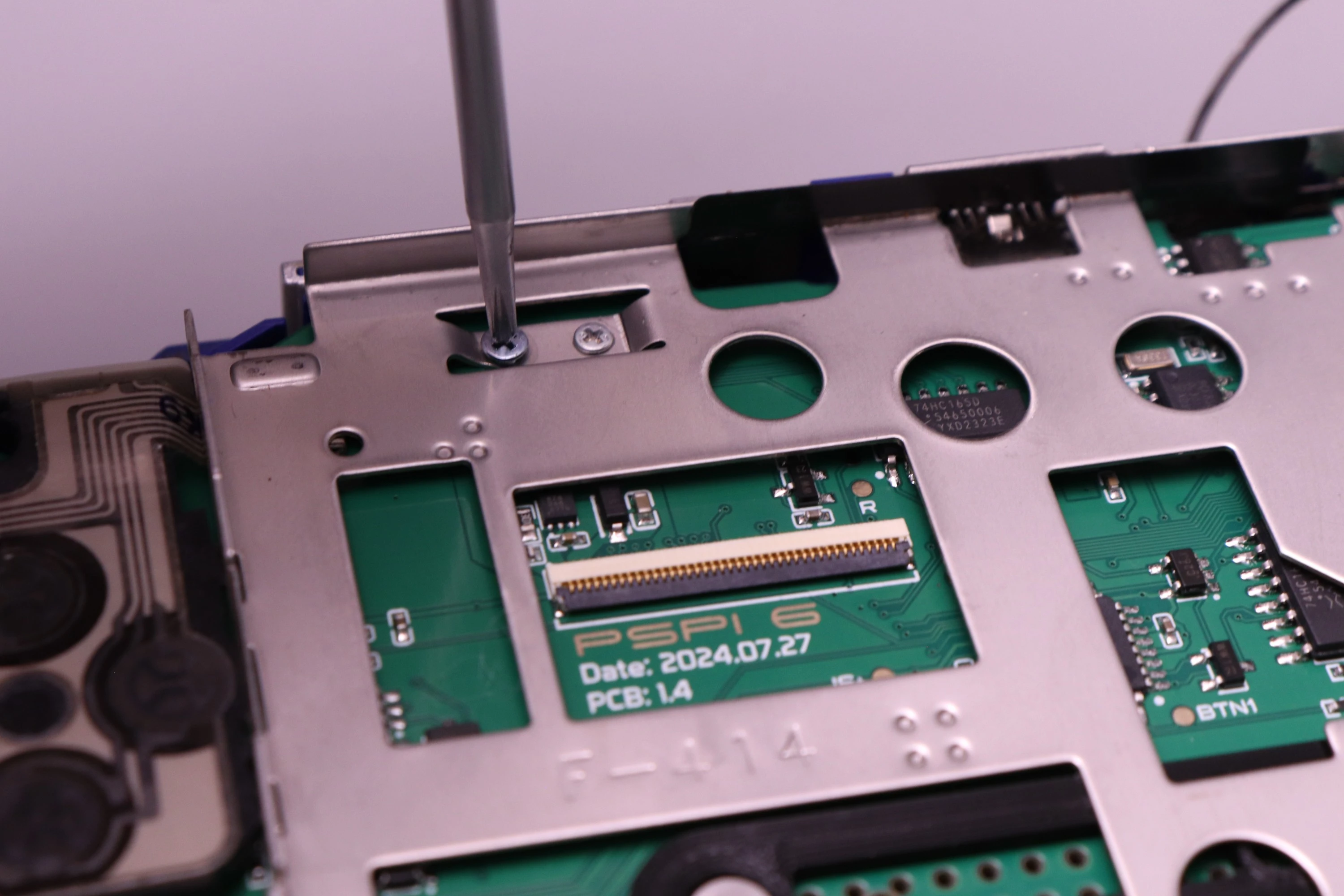
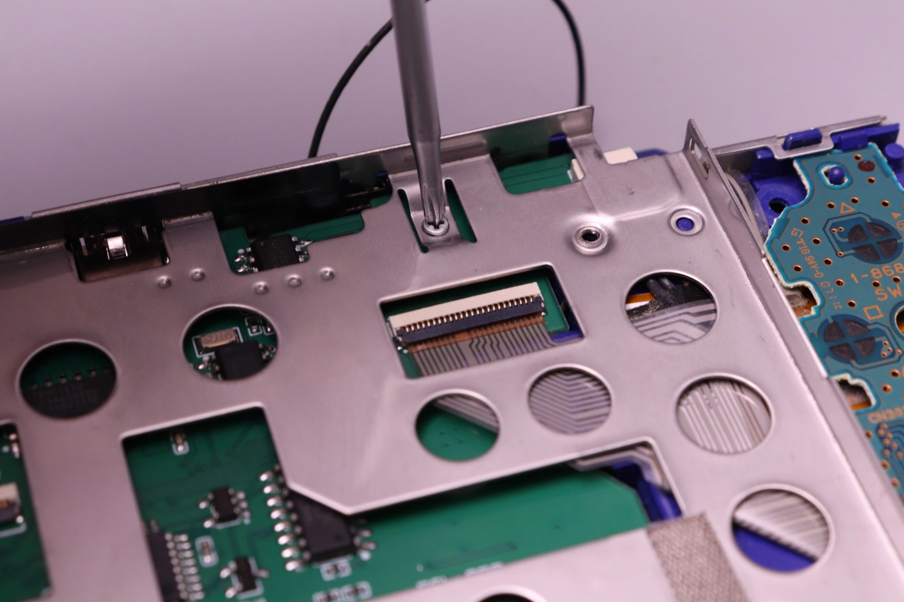
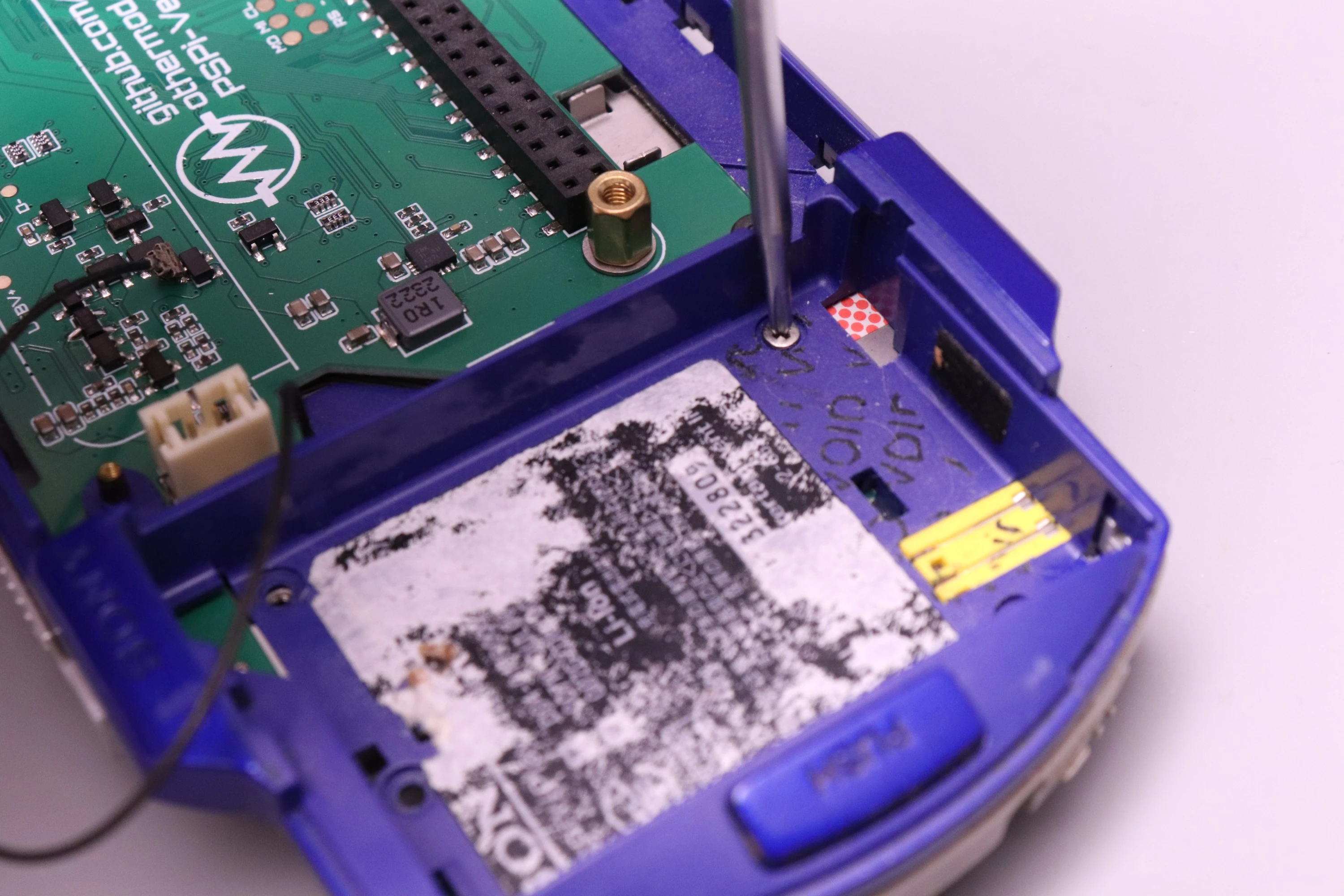
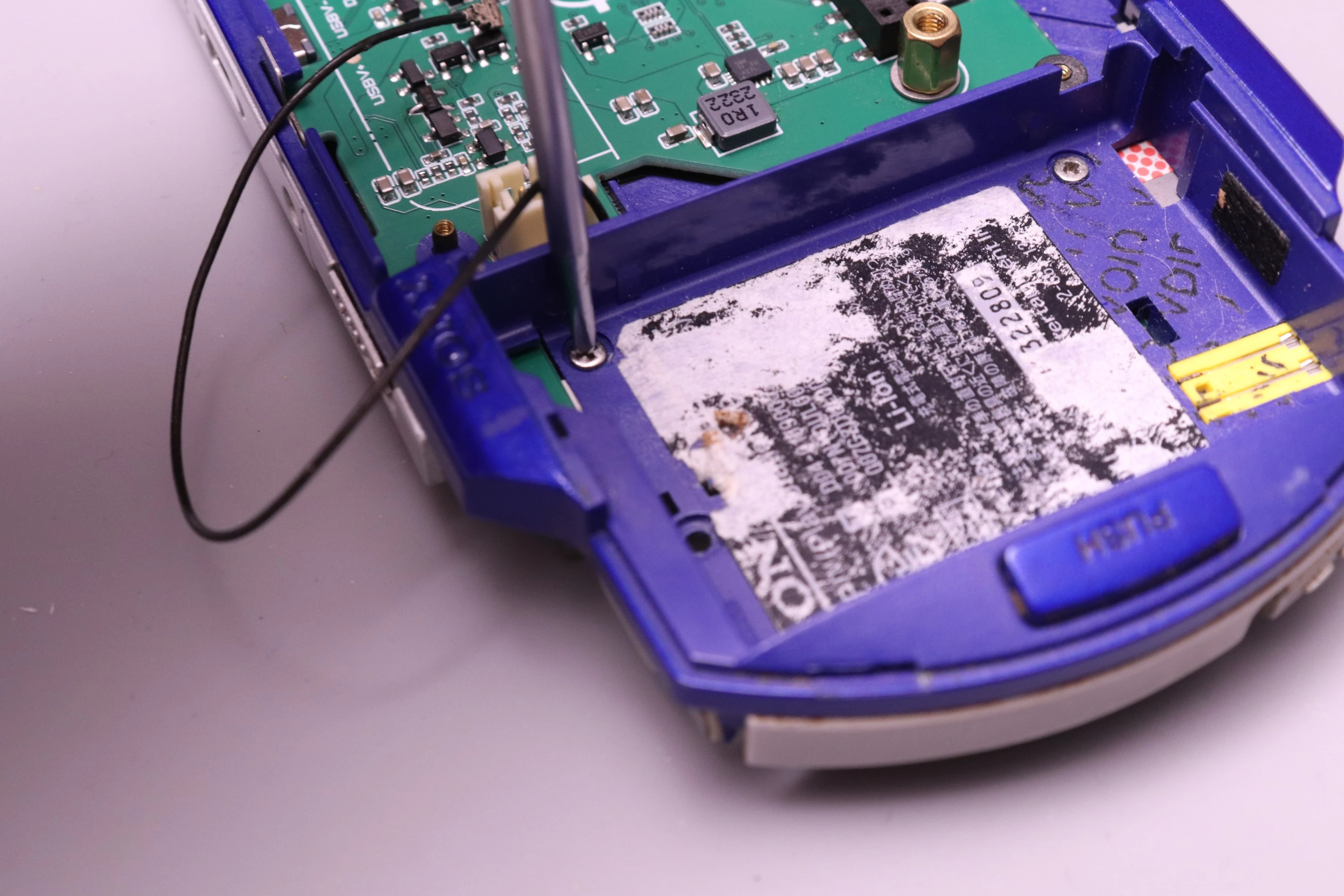
Now install a single screw into the PSPi mainboard. The screw hole is marked with a circle around it. This is the same type rough-thread silver screw that's used for the D-Pad. Tighten it until flush, but don't crank down too hard. The board may need to shift slightly during the next step.
 |
 |
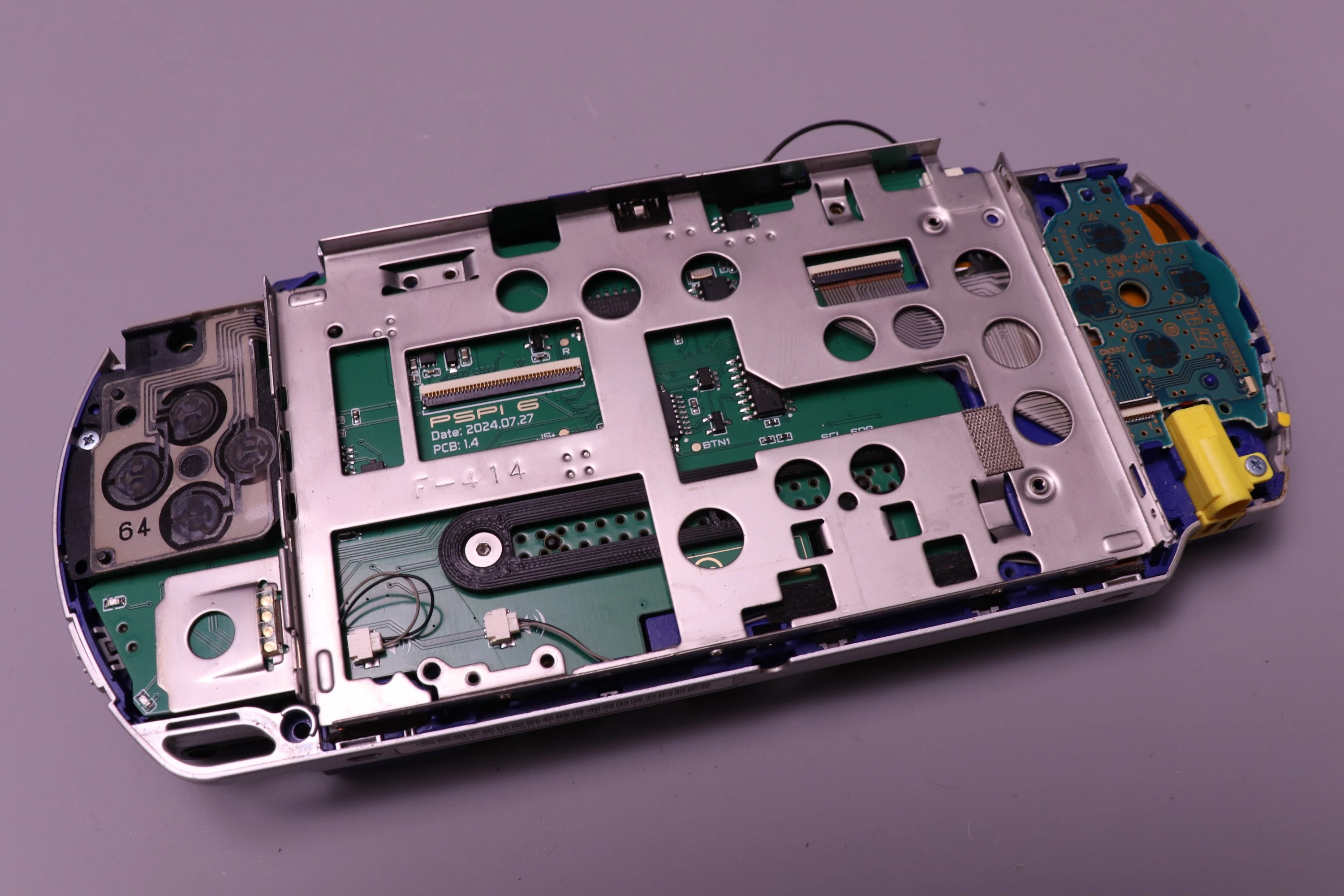
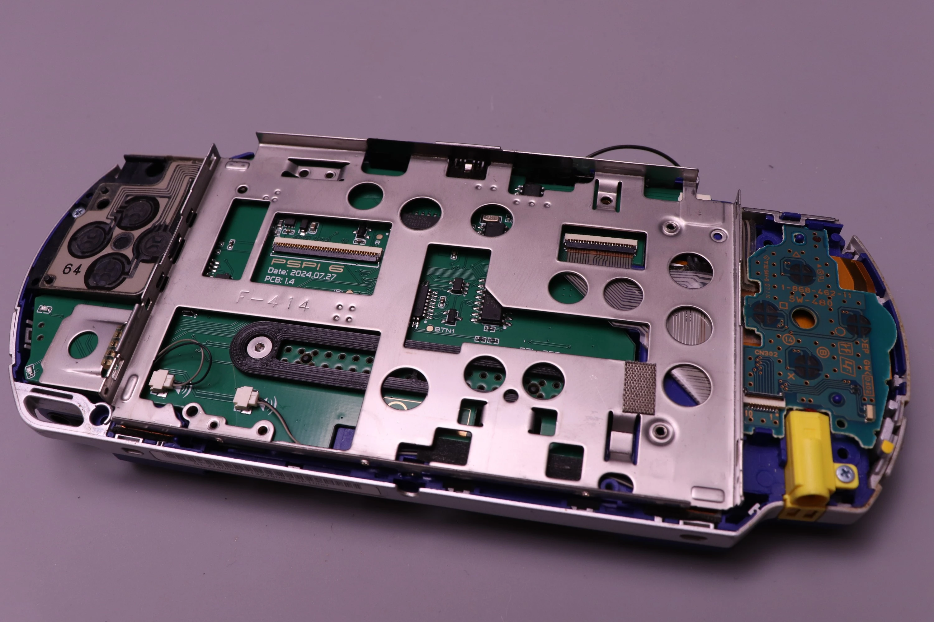
Install the LCD bracket over the mainboard.
 |
 |
Before installing any screws, we need to check alignment. The D-Pad has some protruding plastic that sits in a groove on the LCD bracket. Make sure it is properly seated.
 |
 |
Now begin installing the LCD bracket screws, but only loosely. The bracket may need some minor adjustments in the next step. Just ensure all of the screws have a few threads engaged. There are a mix of rough-thread and fine-thread screws used in the bracket. The ones with a smaller head are fine thread. Not all of these screws are critical, but the more you install the better.
Important Note: The PSP has two fine-thread screws that are slightly larger diameter than the others. These cannot be installed on the top of the LCD bracket, and you'll cause damage if you try. They go into the battery compartment.
 |
 |
 |
 |
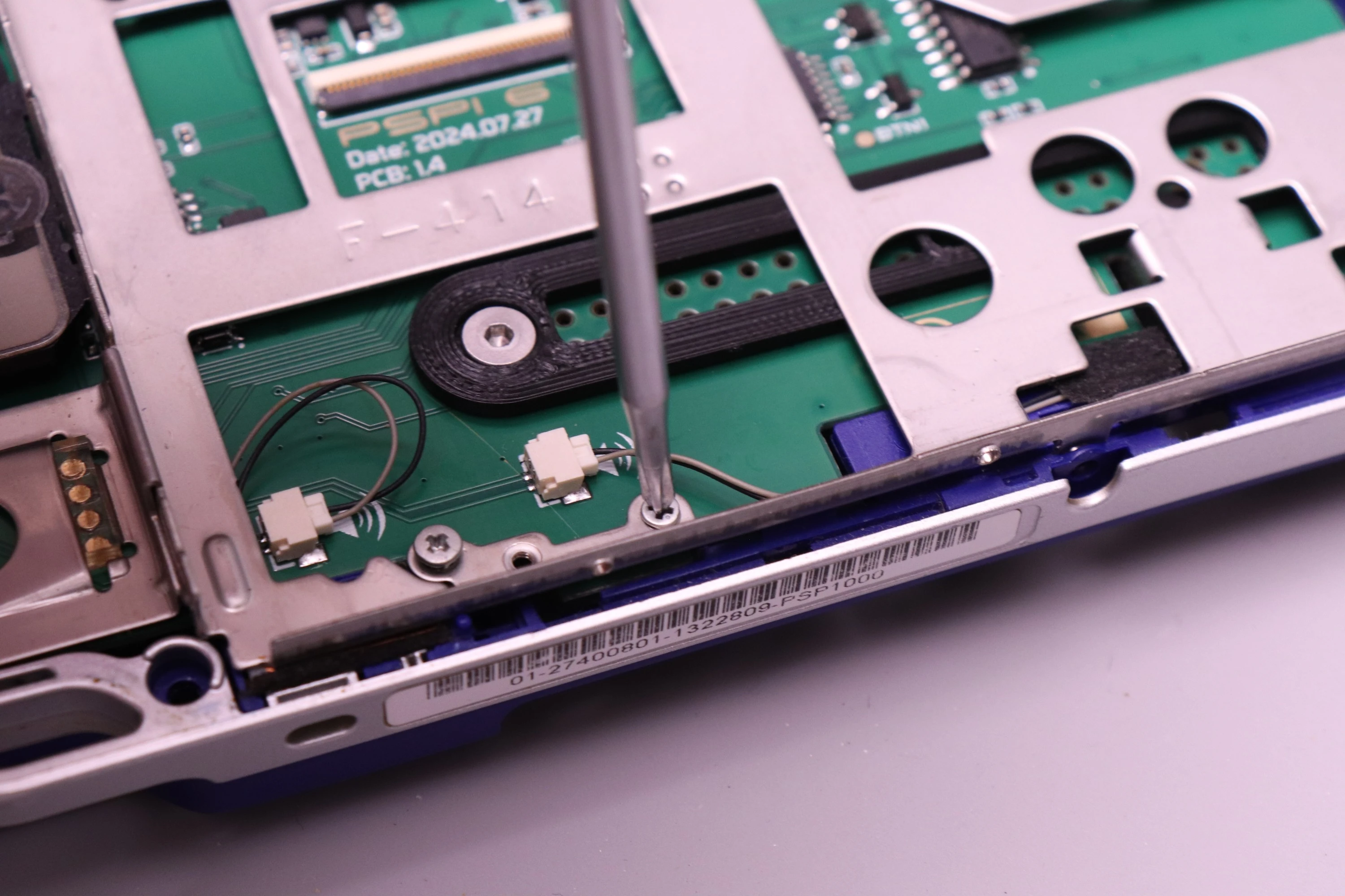 |
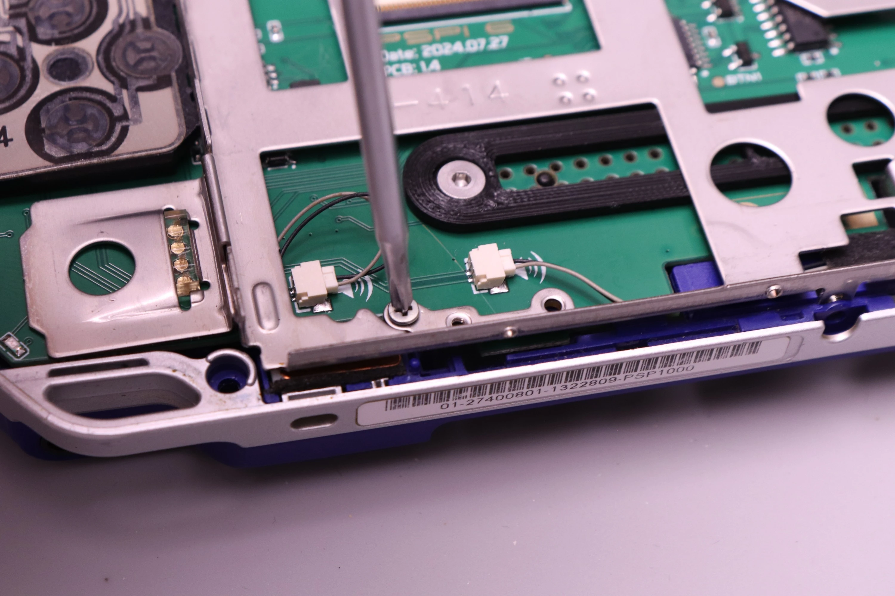
Now the two larger machine screws get installed from the battery compartment. Remember to keep everything slightly loose so we can make those adjustments.
 |
 |
 |
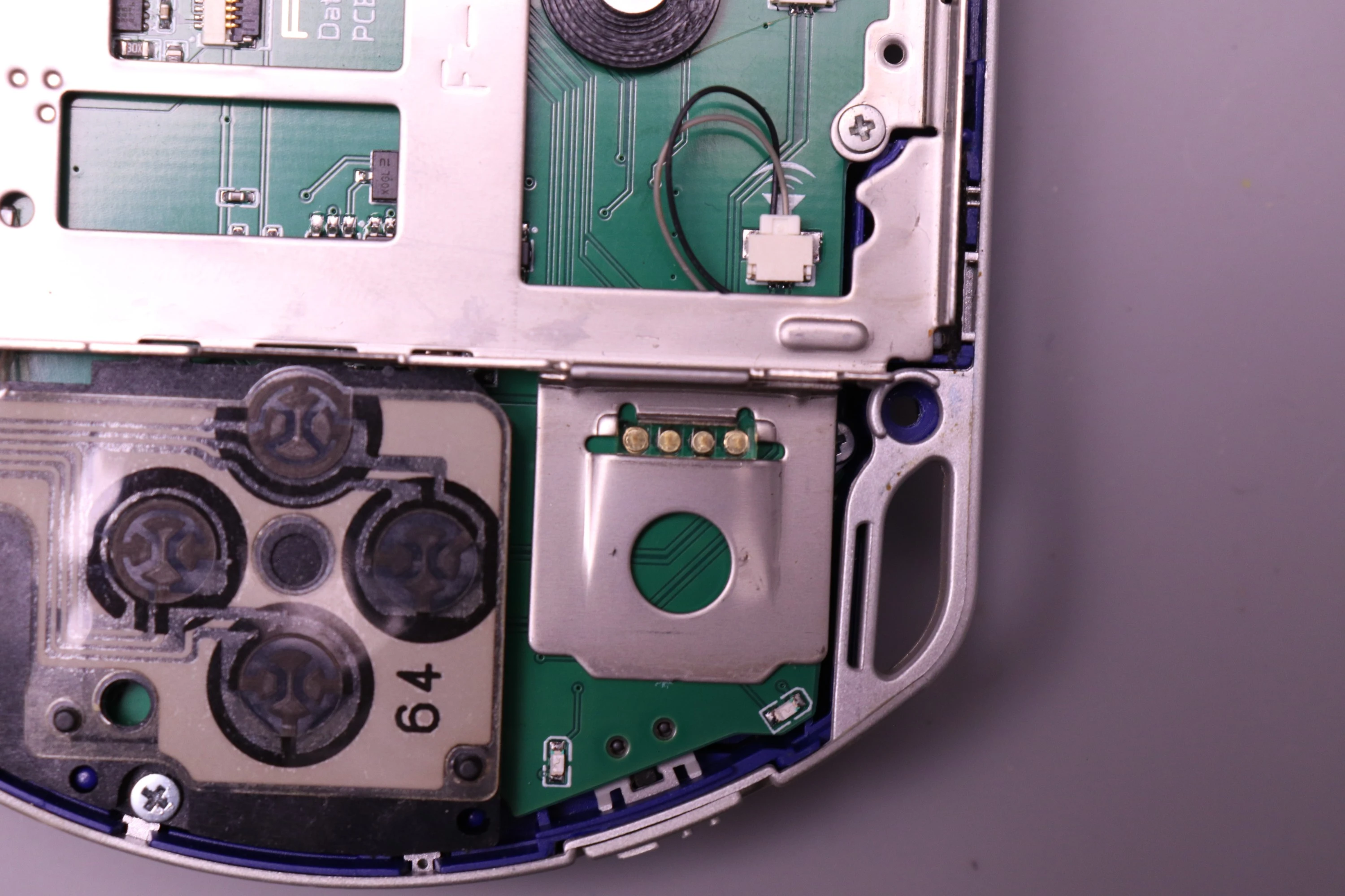
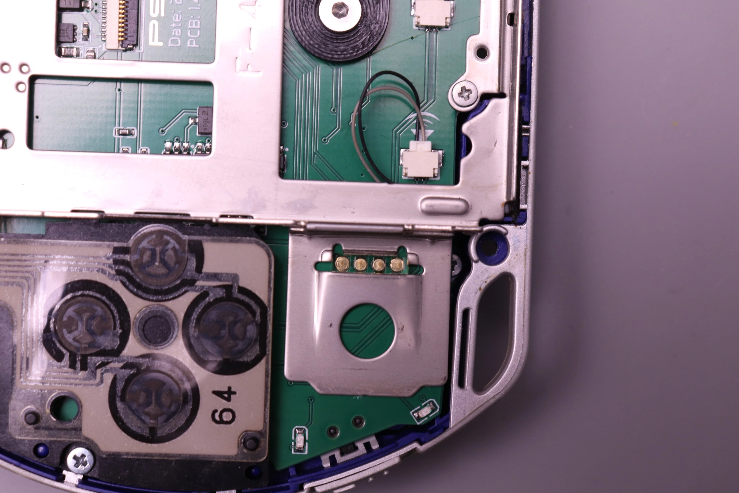
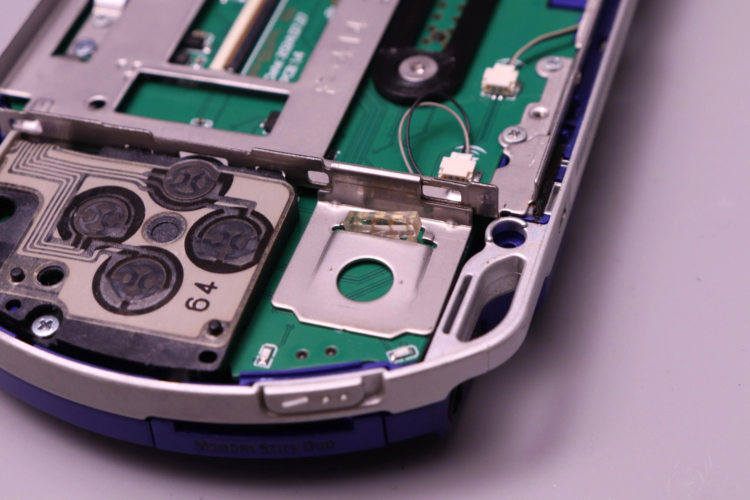
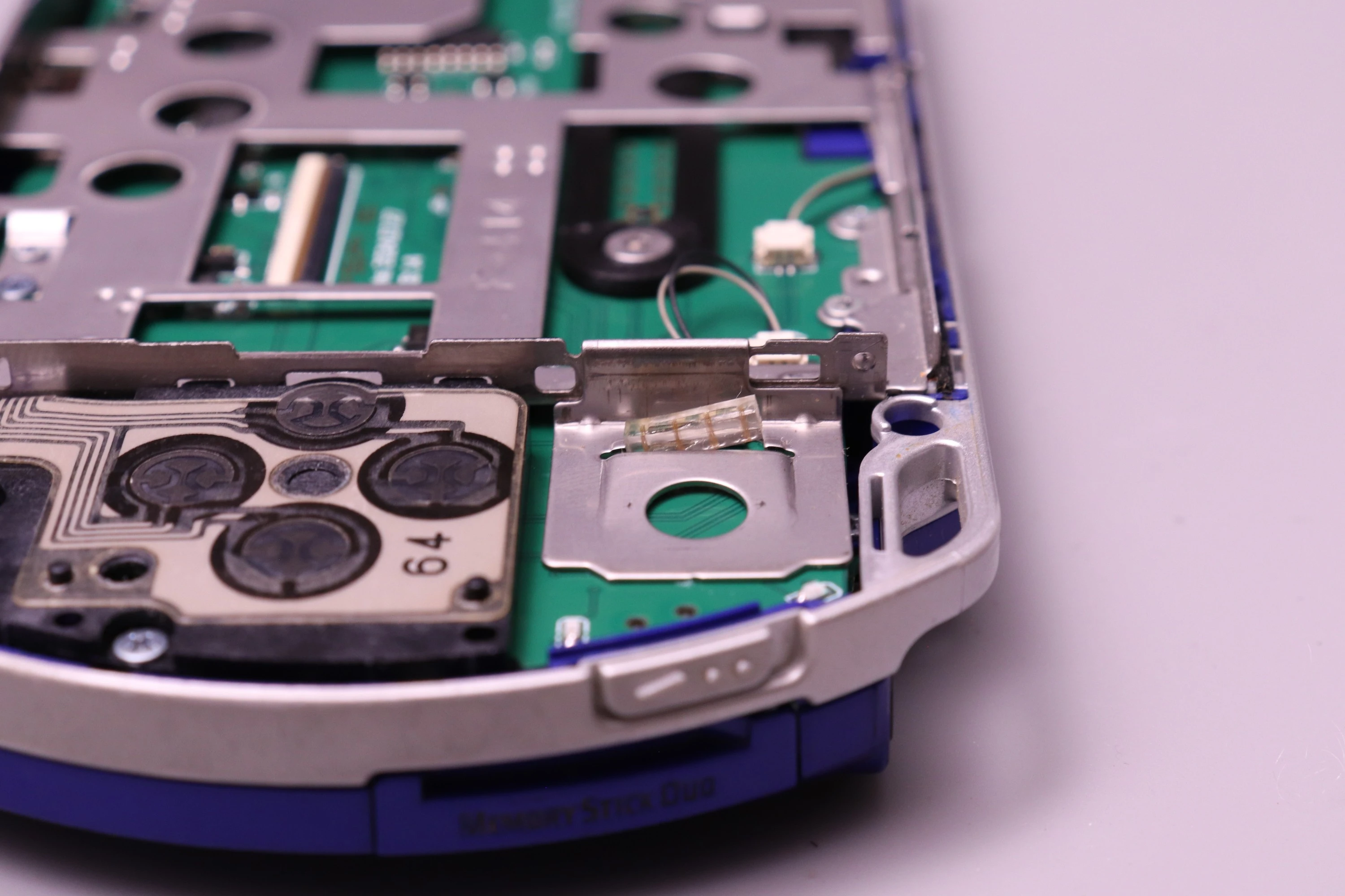
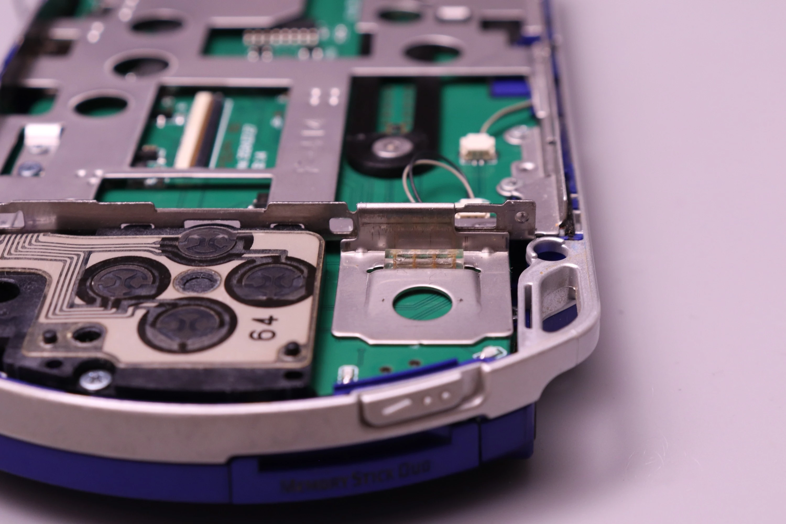
This is a critical step because the joystick pads on the mainboard protrude slightly, and they need to be centered in the bracket opening.
If the pads contact the metal frame, this will create a direct short on a power rail and can cause permanent damage. Carefully check the alignment and make sure that the pins are approximately centered in the opening. It doesn't have to be perfect, as long as there's a small gap between the pads and the metal before fully tightening the screws.
 |
 |
 |
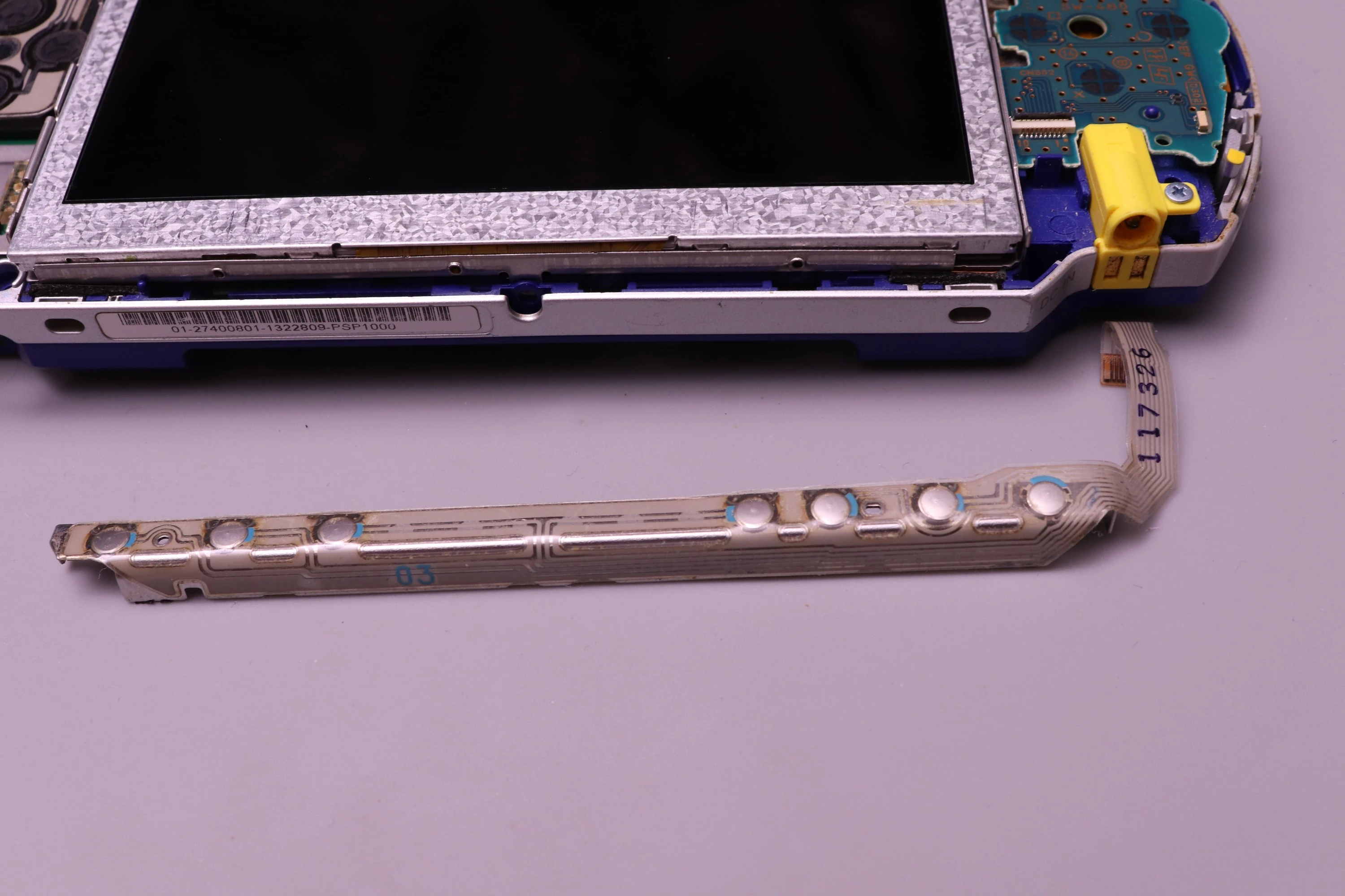
The joystick membrane is the rubber component with conductive pads that sits between the joystick and the mainboard. Install it with the conductive tracing running up to down (toward the PSPi 6 board's gold-plated contact pads). Ensure the membrane is properly seated and not twisted or pinched when the LCD bracket is installed, as this would prevent the joystick from working.
 |
 |
 |
 |
Take the 40-pin FPC cable from the LCD and insert it into the connector on the PSPi 6 mainboard. This connector is the same as the others, so lift the retainer, insert the cable fully, and flip down to secure.
 |
 |
 |
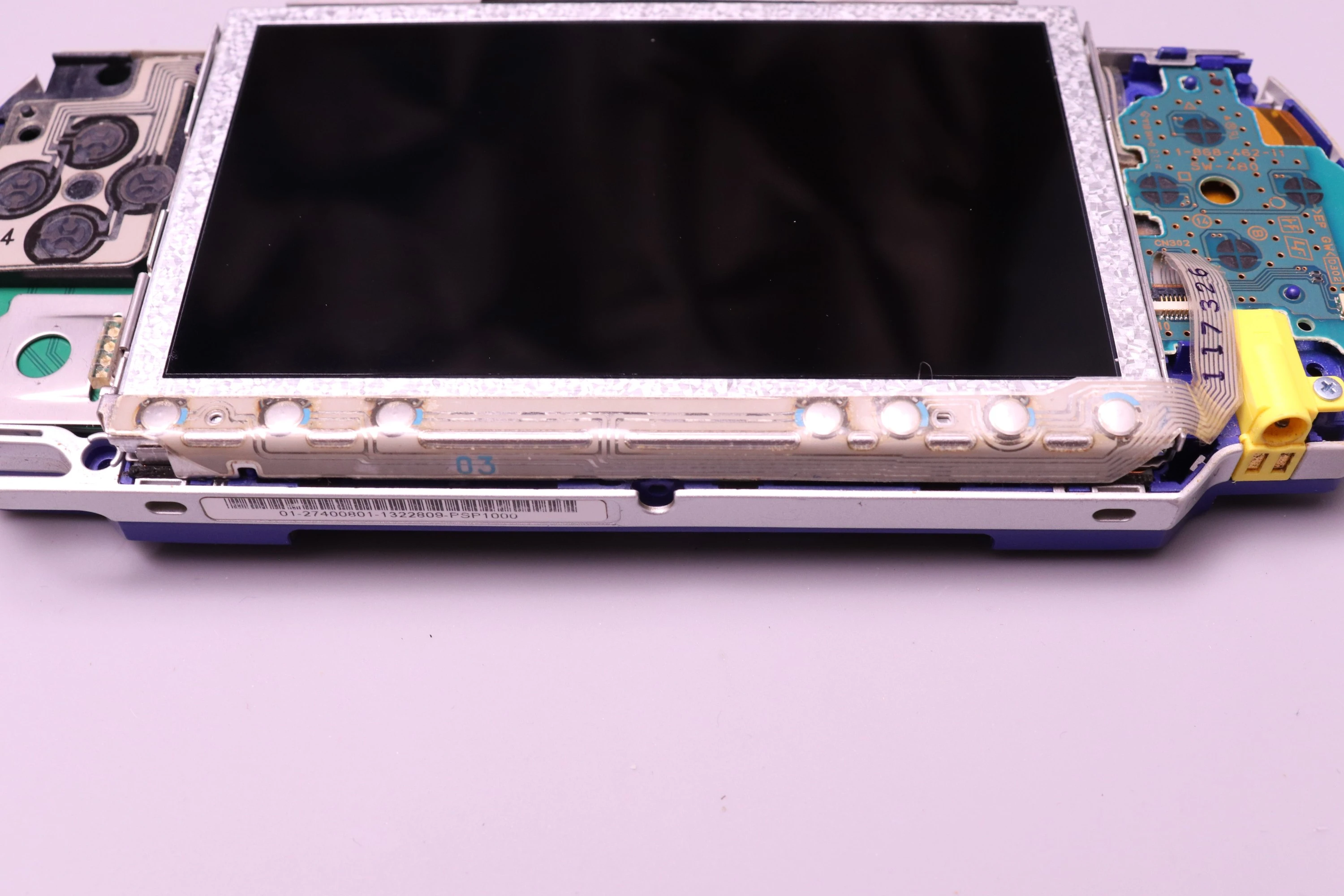
Then set the LCD into the bracket.
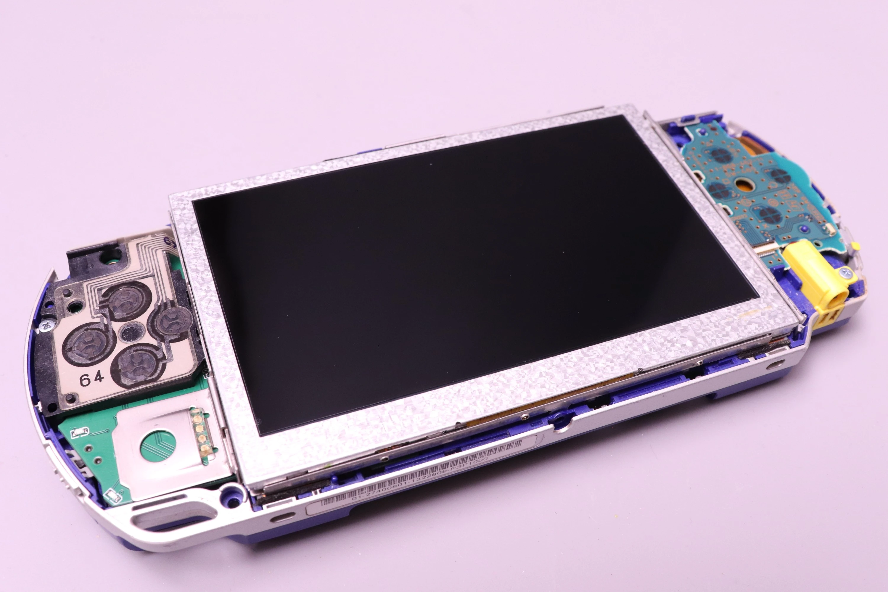 |
 |
Next we install the LCD Buttons. It has a small FPC cable that functions the same as others from earlier. Lift the retainer, install the FPC cable, and latch it down.
The Button Board is held to the LCD bracket by two clips that attach to nubs on the bracket. Align the clips with the nubs and press down until they snap into place.
 |
 |
 |
 |
Install the left and right trigger buttons. The rubber contact pads and retainers should already be in place from the original PSP.
 |
 |
Set the faceplate in position.
 |
 |
Install the 5 remaining screws. 4 black screws for the main casing. 1 silver fine-thread screw for the bottom (this is the only screw of this type).
 |
 |
 |
 |
 |
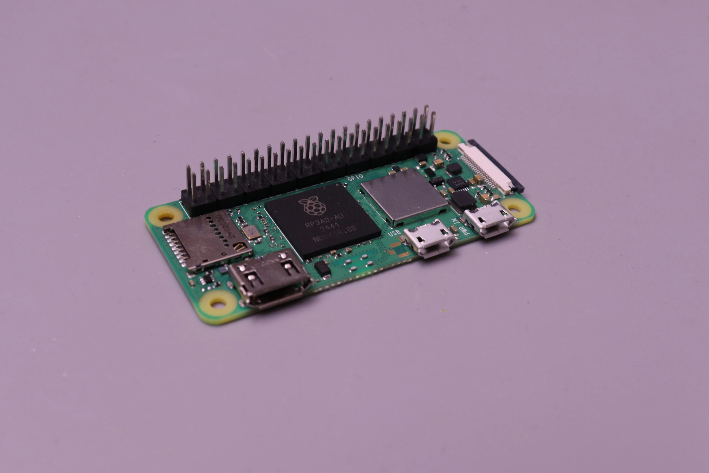
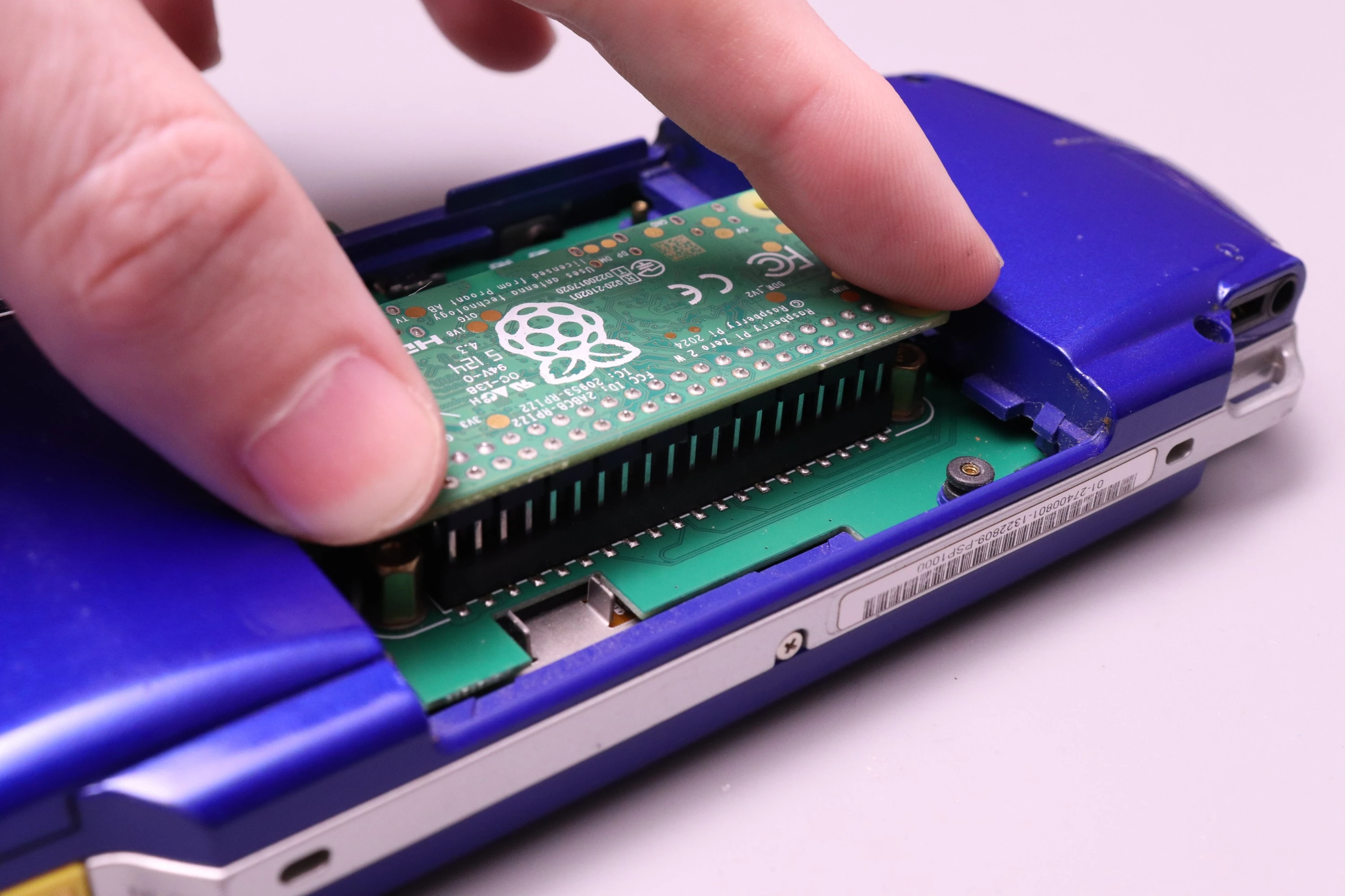
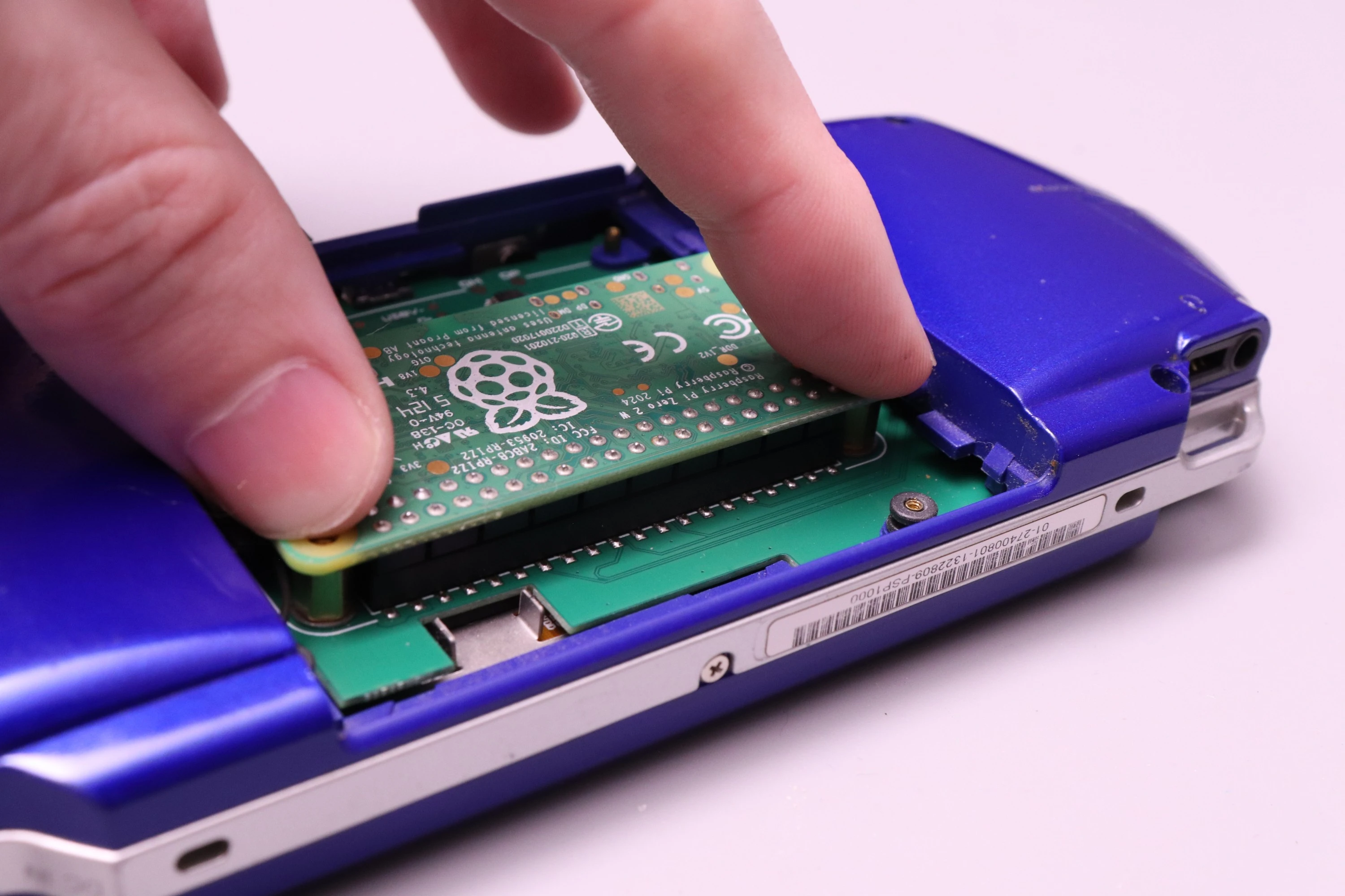
The Raspberry Pi Zero inserts directly into the 40-pin header on the PSPi 6, with no adapter needed.
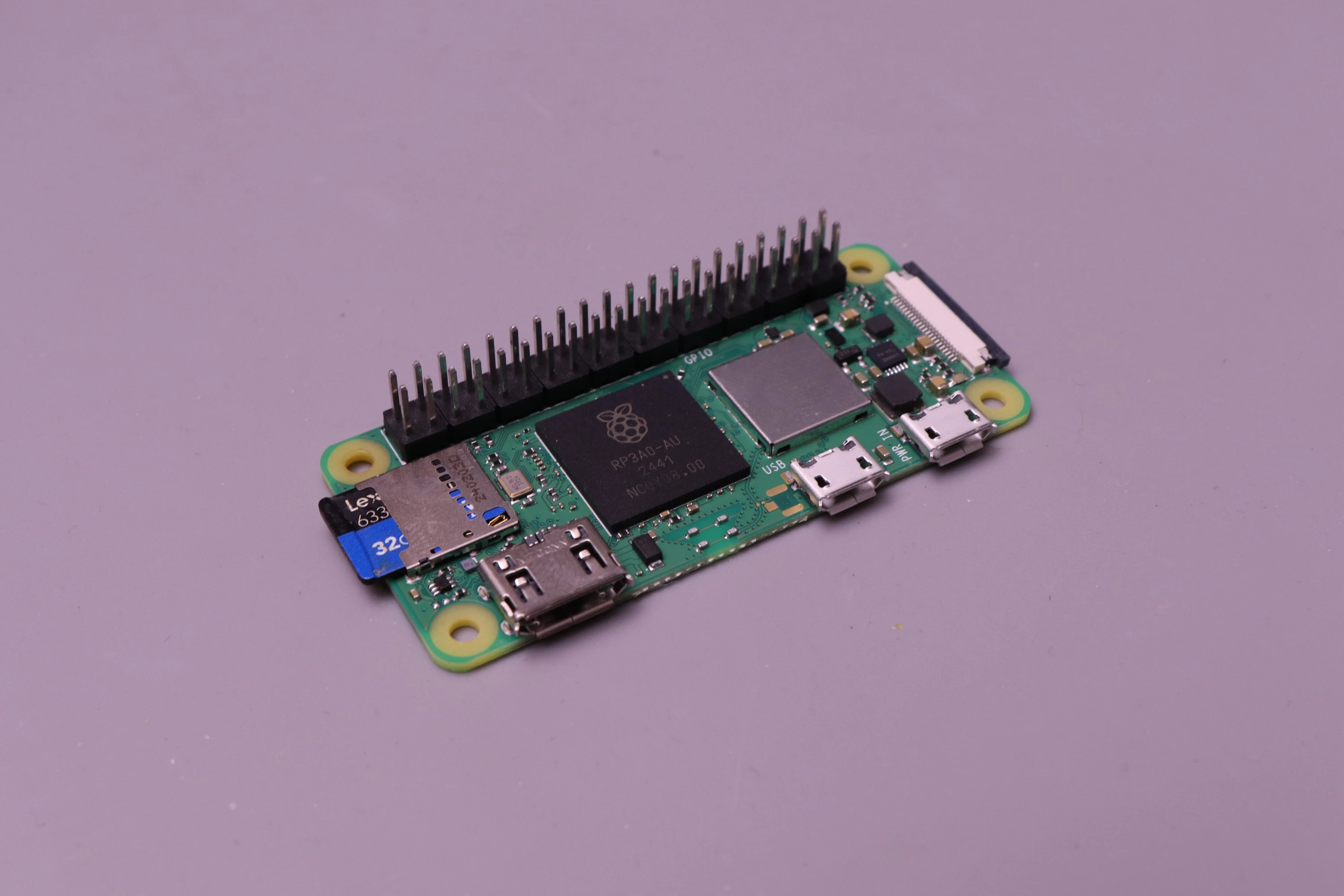
Before installation into the PSPi, install the SD card into the Raspberry Pi.
 |
 |
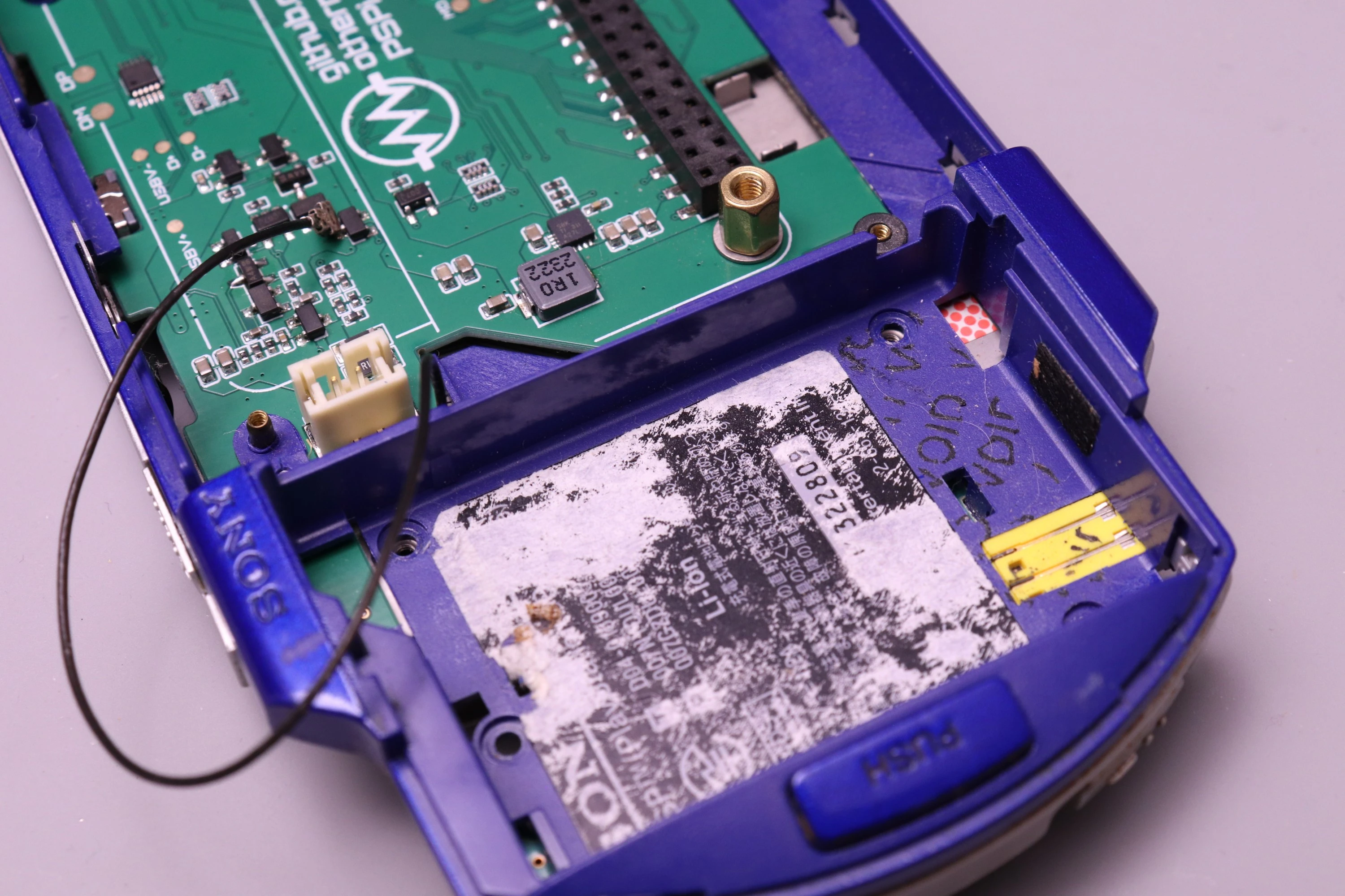
The PSP WiFi Antenna cable isn't used on the Pi Zero (unless you intend on adding a connector to the Zero), so the wire can be tucked away into the battery compartment.
 |
 |
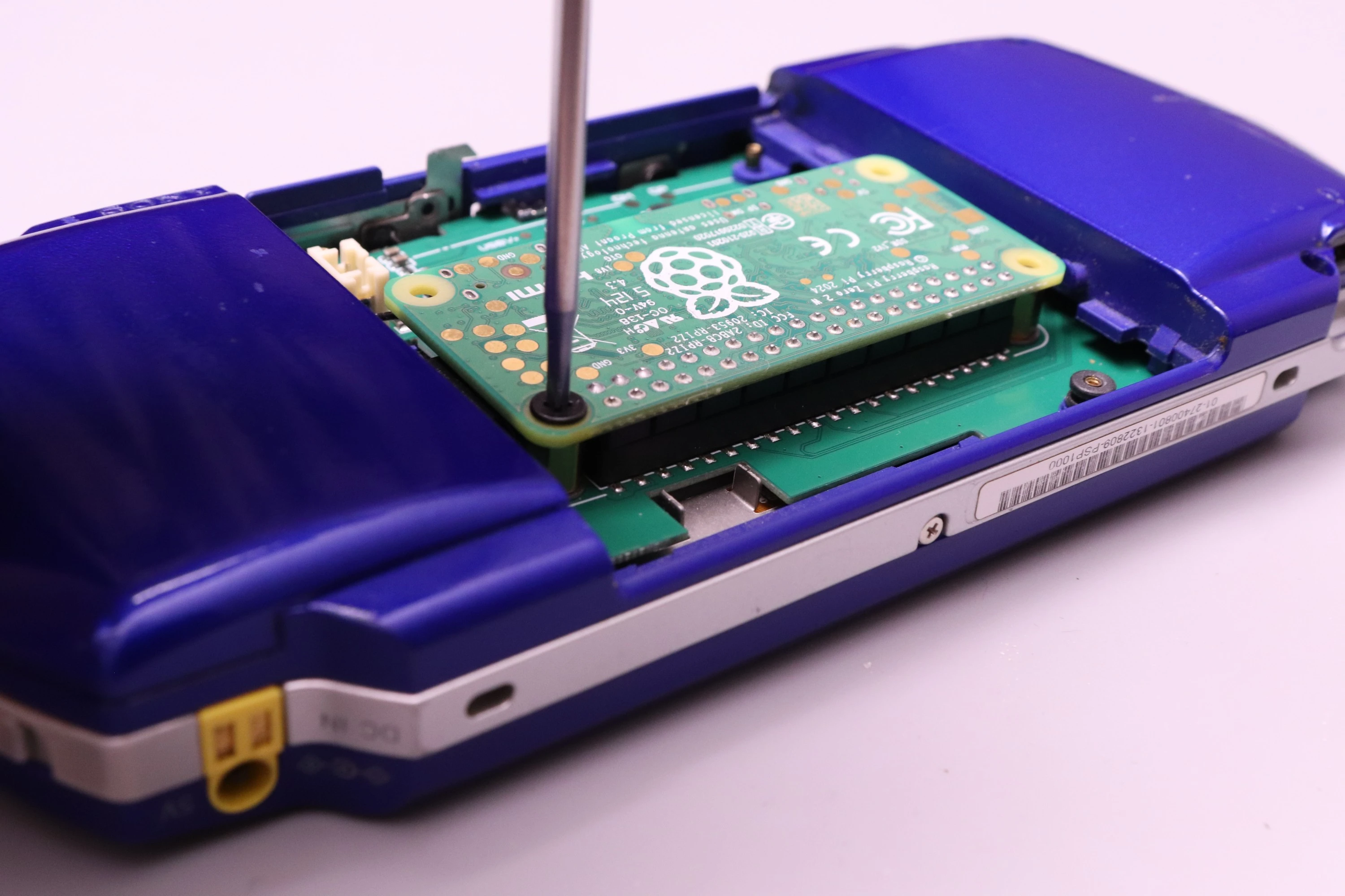
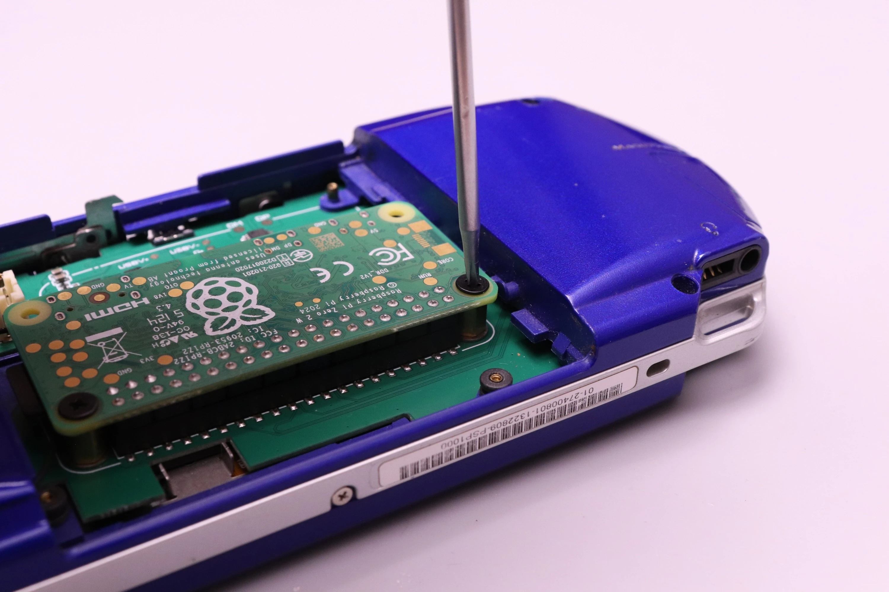
Now install the Pi Zero into the PSPi. Line the 40 header pins up with the female connector on the PSPi, and press down. Rocking the board a bit while pressing down will make the process easier. Keep pushing it down until it meets up with the brass standoffs. Then install the two screws.
 |
 |
 |
 |
The Pi Zero has a microUSB port which will function for using USB devices, but you can also route these USB pins into the miniUSB connector on the PSP. There are pads marked DP and DM on the Raspberry Pi, and similar pads on the PSPi marked DP and DM. To enable this, you can solder a wire from DP on the Pi to DP on the PSPi, and another wire from DM on the Pi to DM on the PSPi.
 |
|
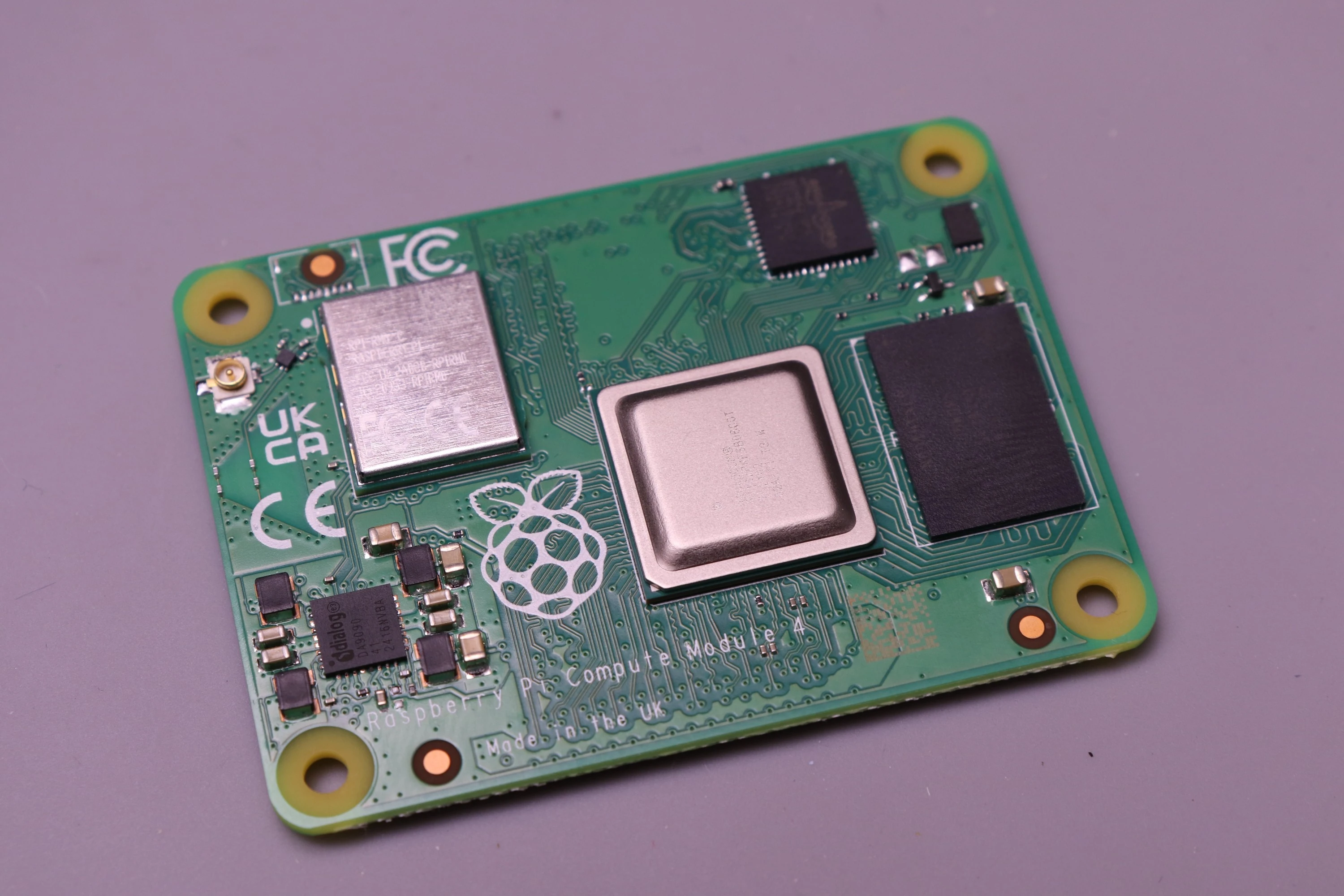
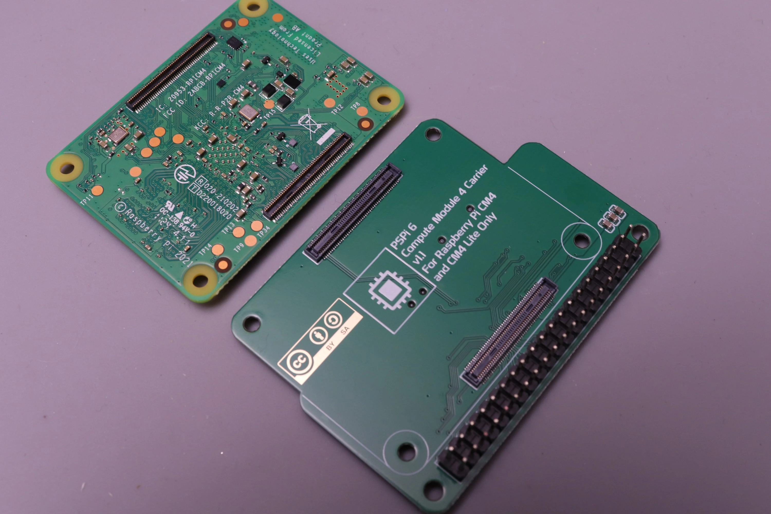
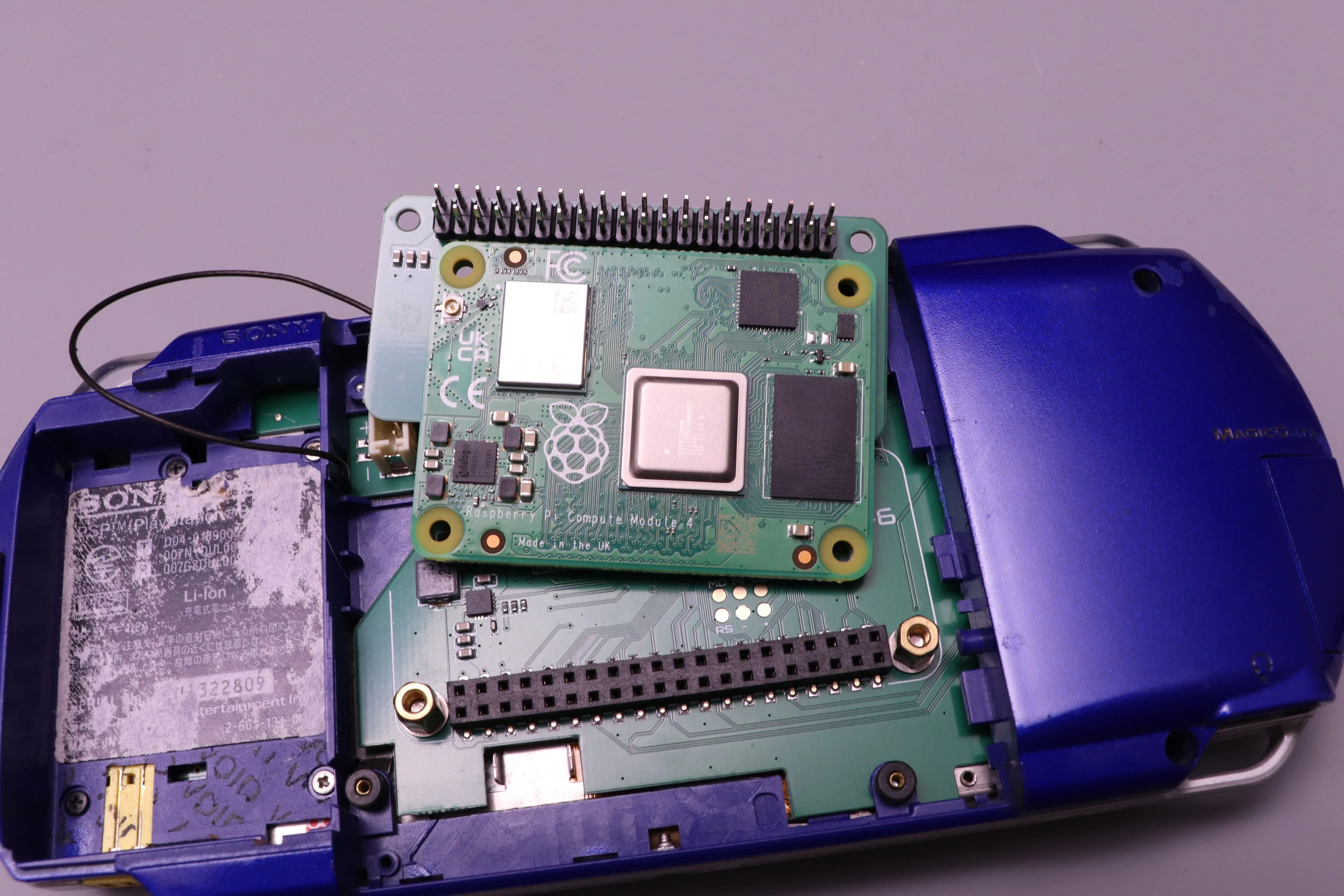
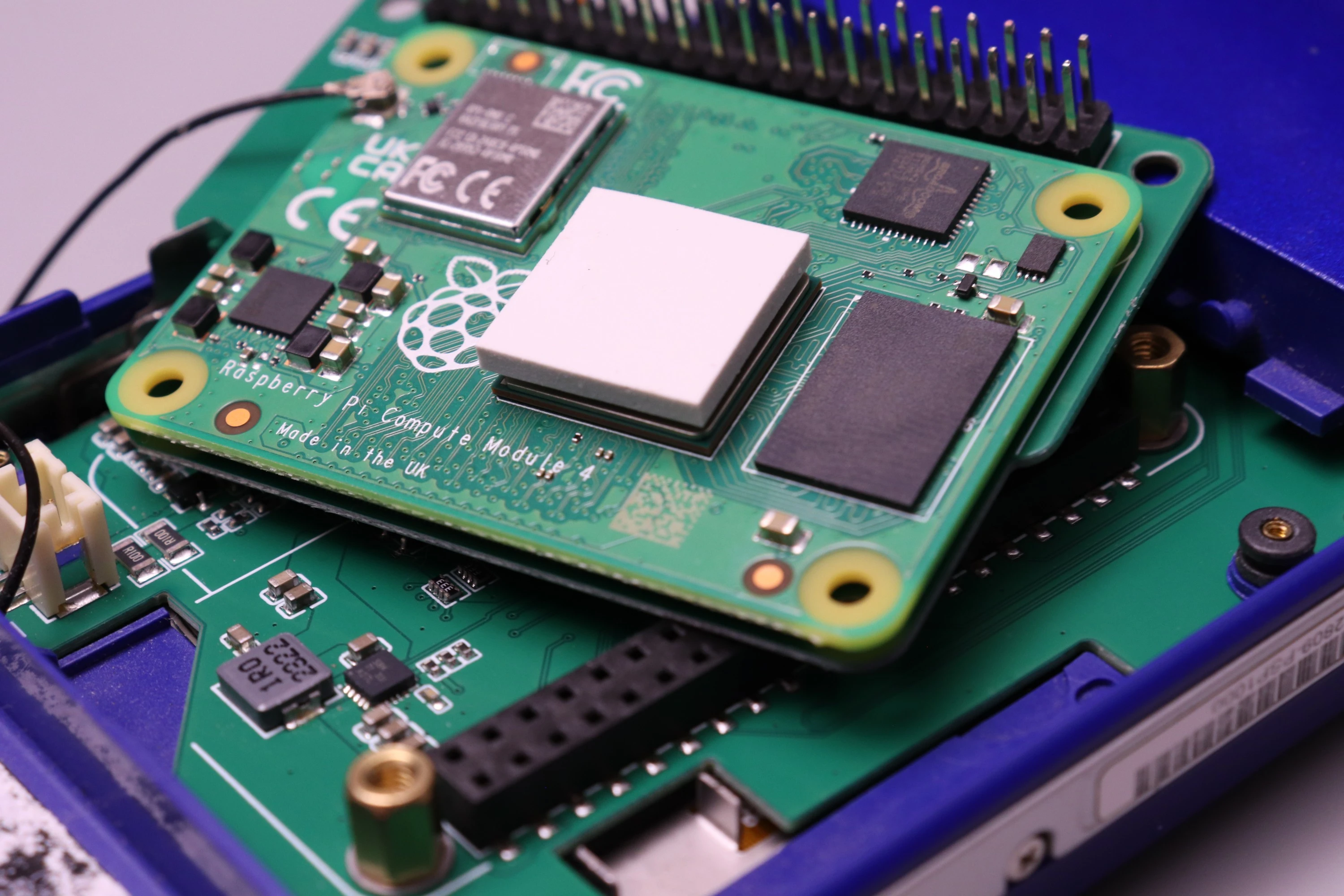
The CM4 requires the CM4 Carrier, which adapts the CM4's 100-pin board-to-board connectors to the normal 40-pin header of the regular Raspberry Pi boards.
 |
 |
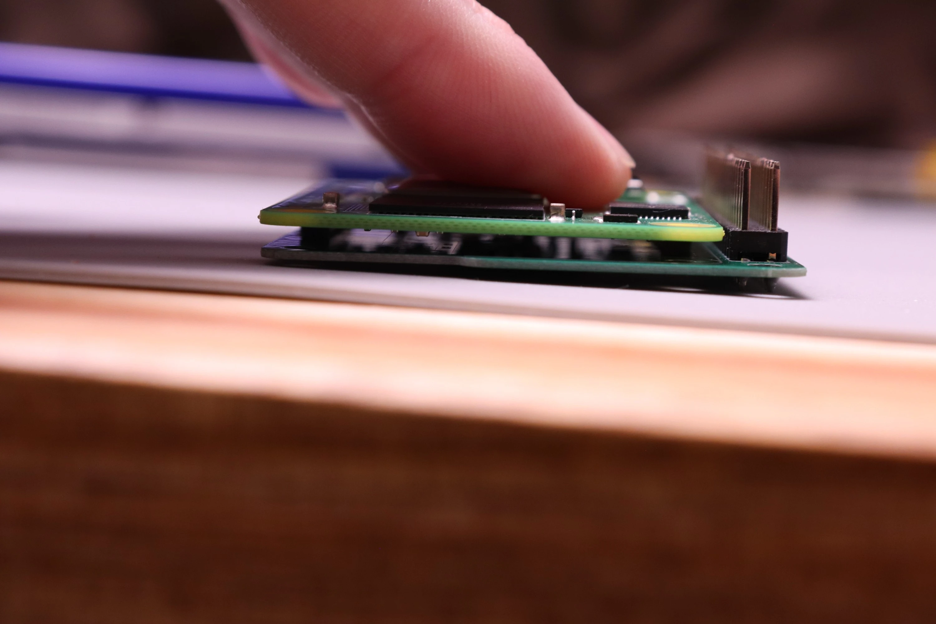 |
This takes some careful work. The two boards must be aligned before trying to press them together. When the alignment looks correct, squeeze the two boards together starting with one side and then the other. You will be able to see the space between the boards decrease as they are pressed together. The distance should be the same all around if the fitup is correct. If not, then remove the CM4 from the Carrier and try again. Both connectors must be fully seated for the board to work.
 |
 |
 |
 |
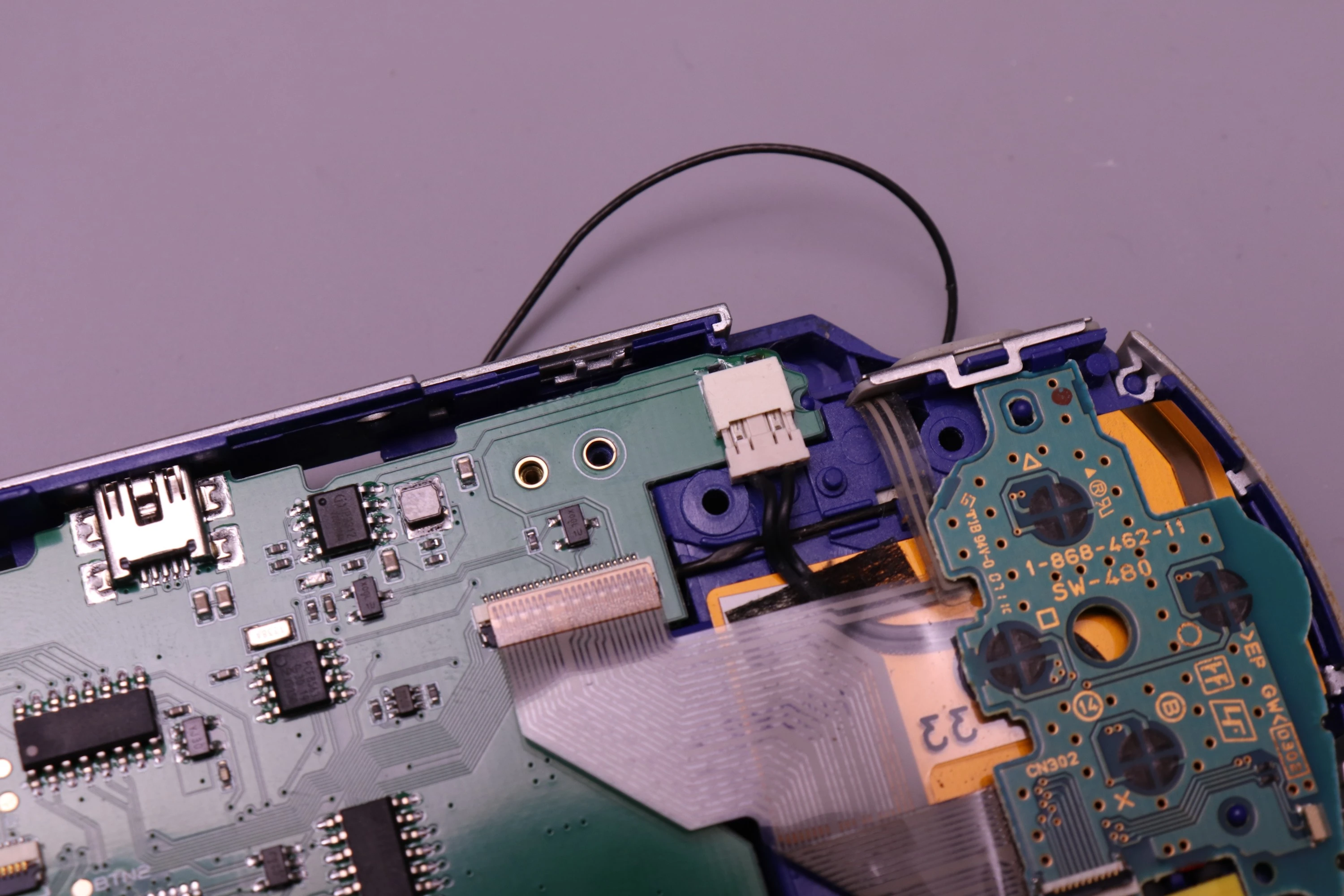
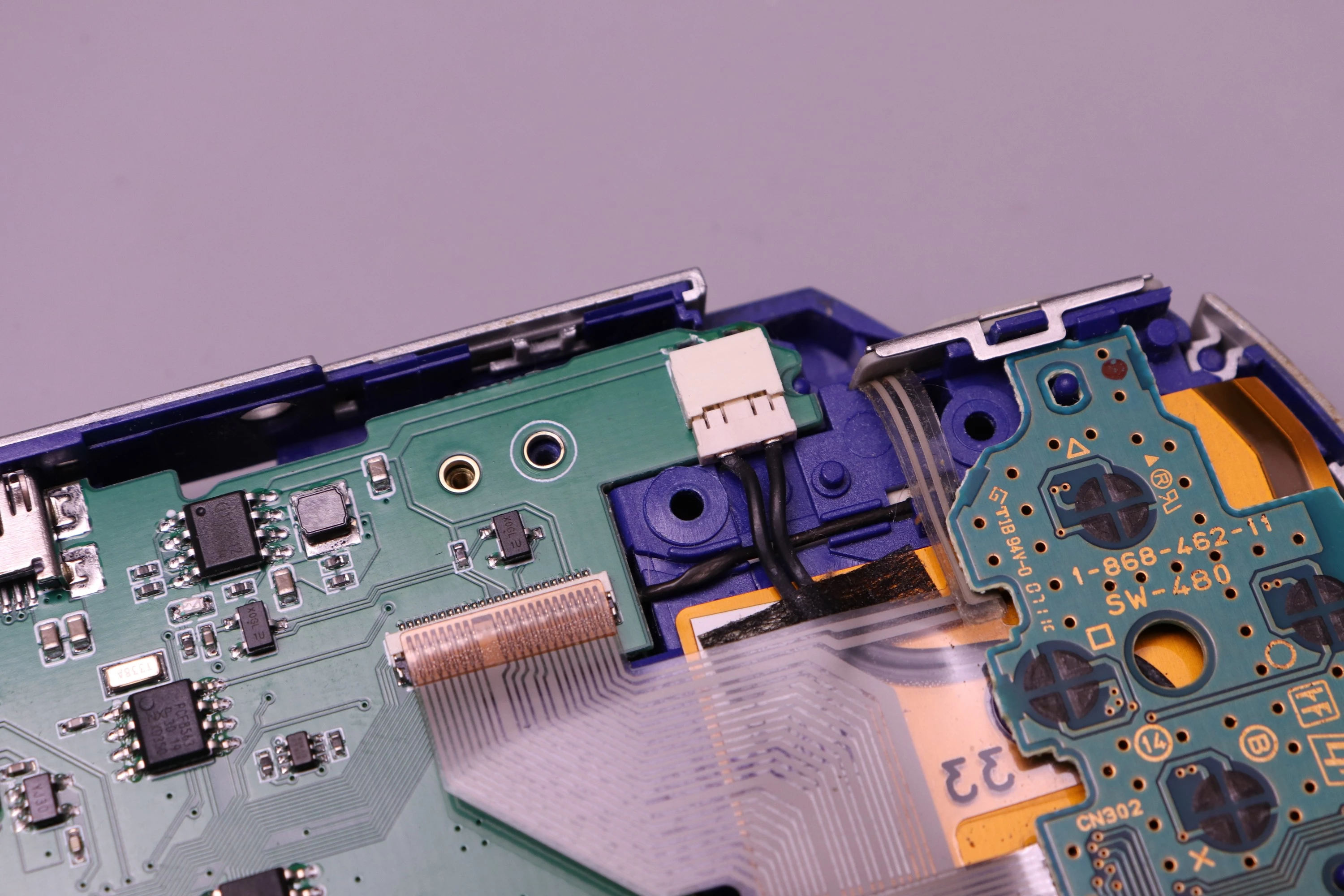
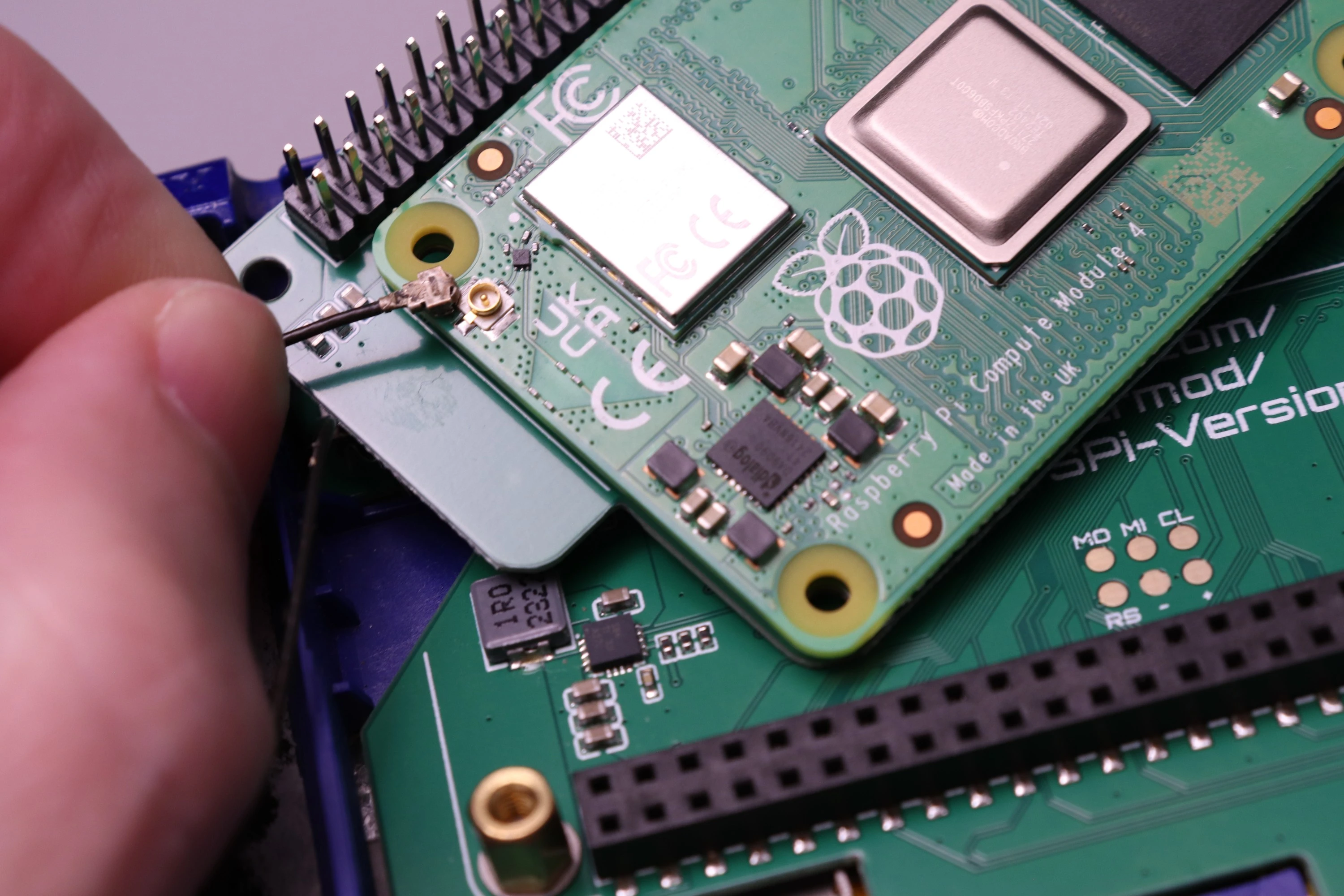
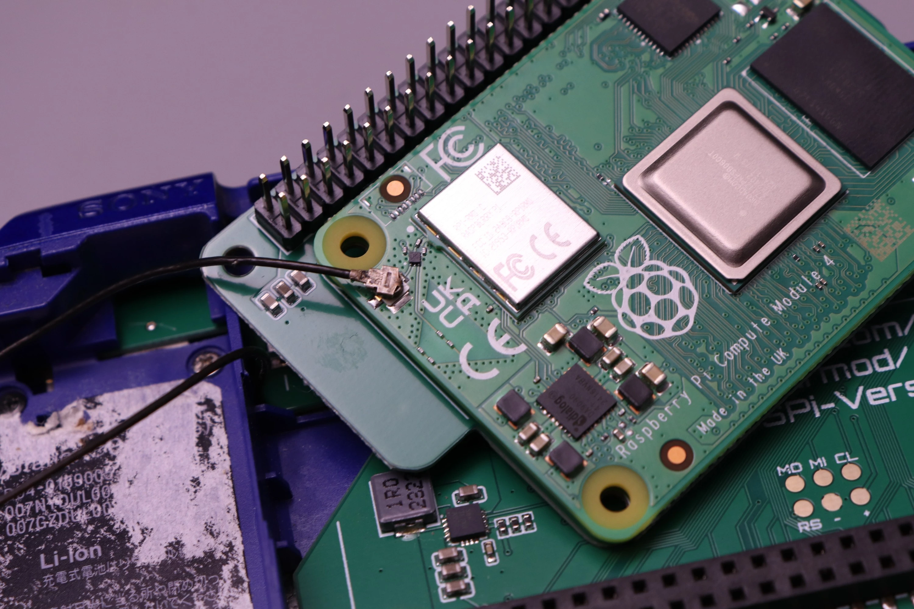
Now attach the PSP WiFi Antenna to the U.FL connector on the CM4
 |
 |
 |
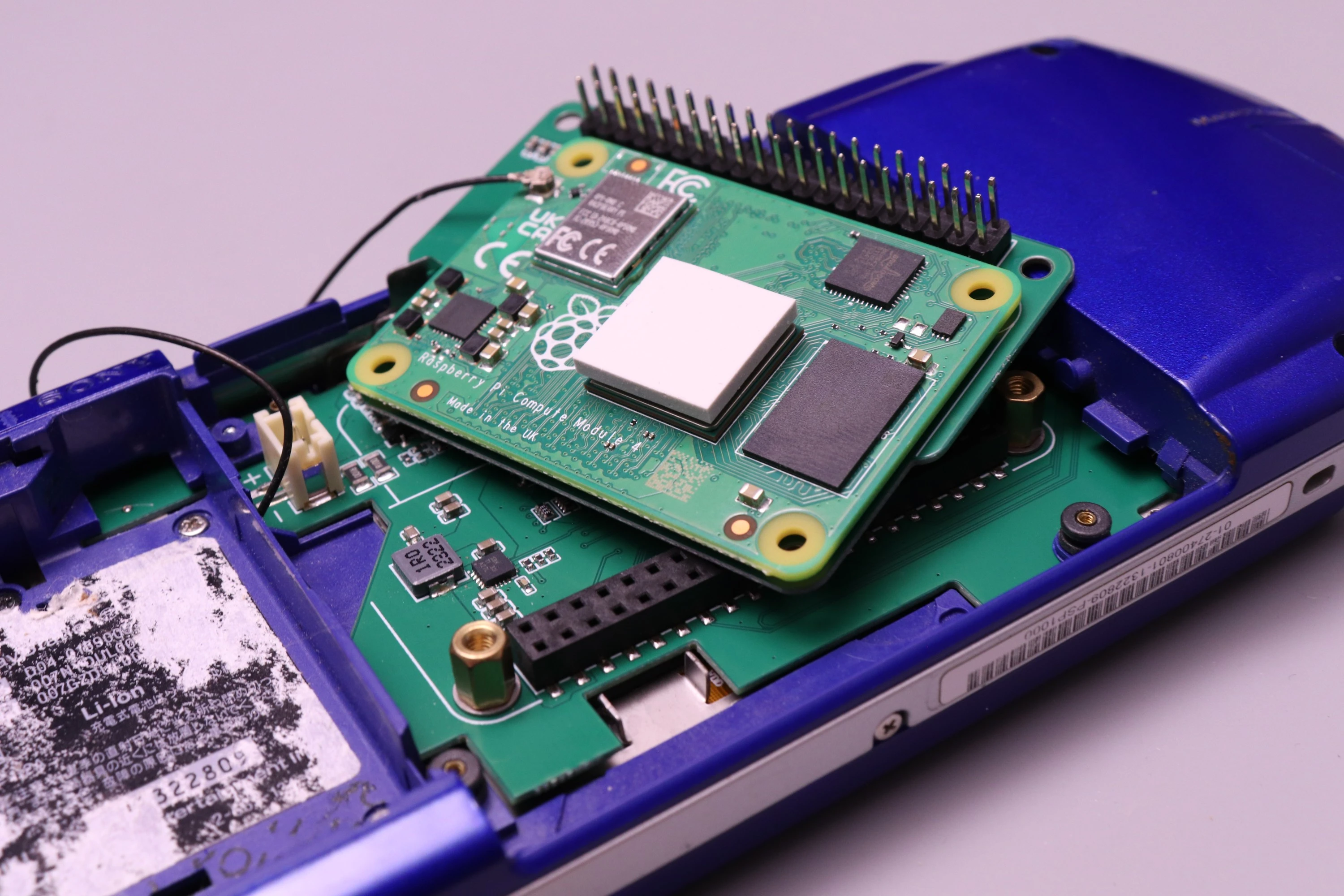
Add the thermal pad to the CM4 CPU
 |
 |
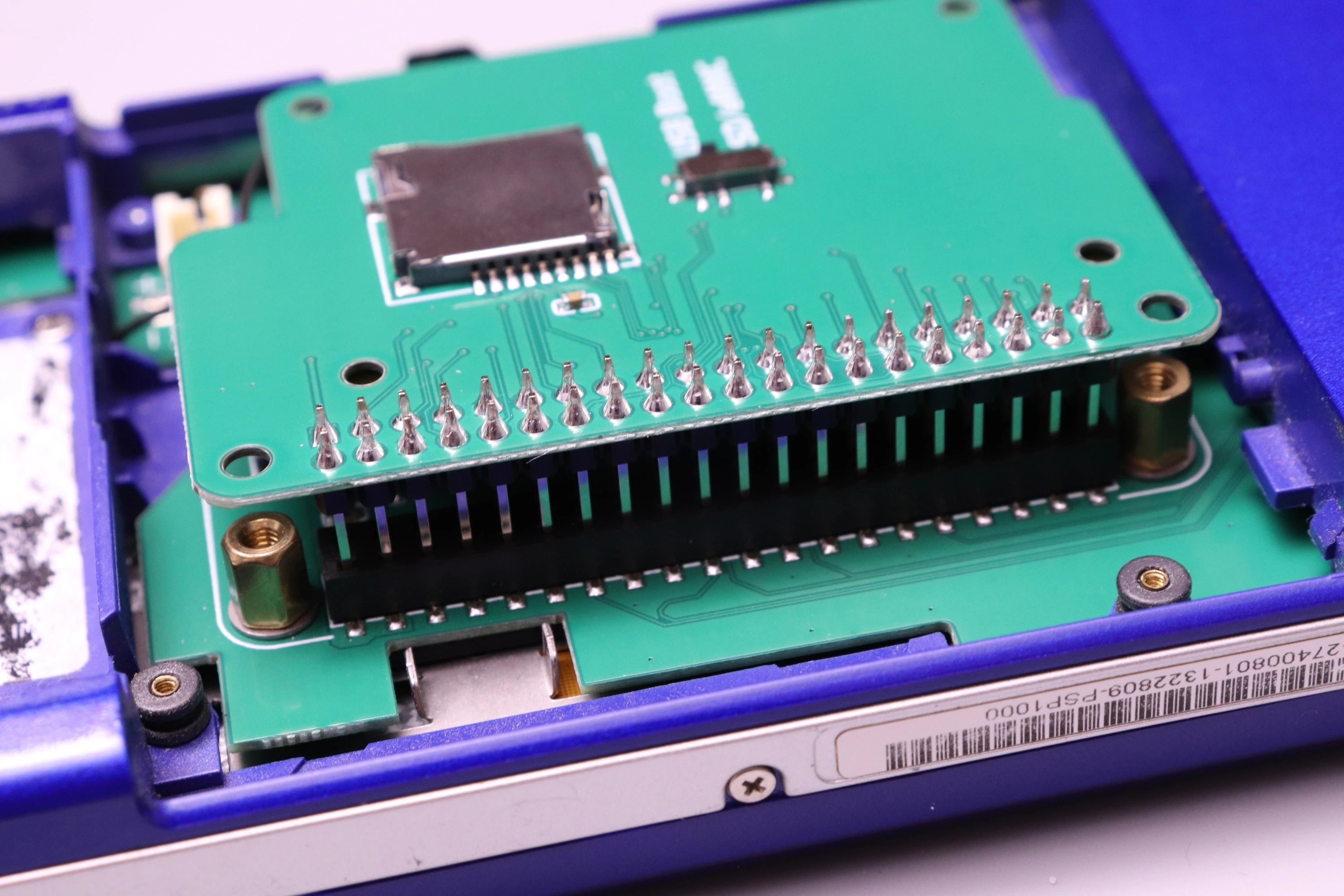
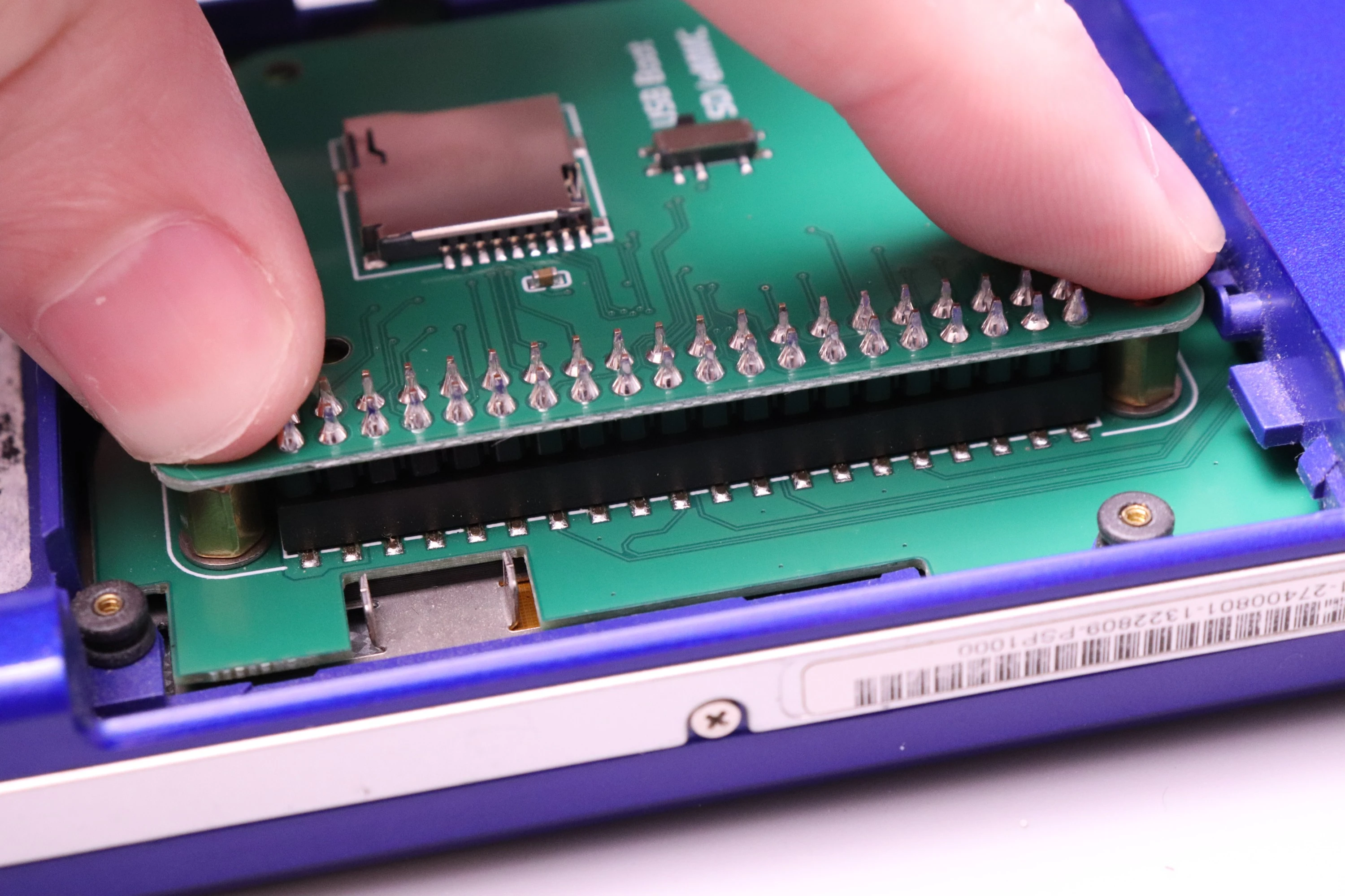
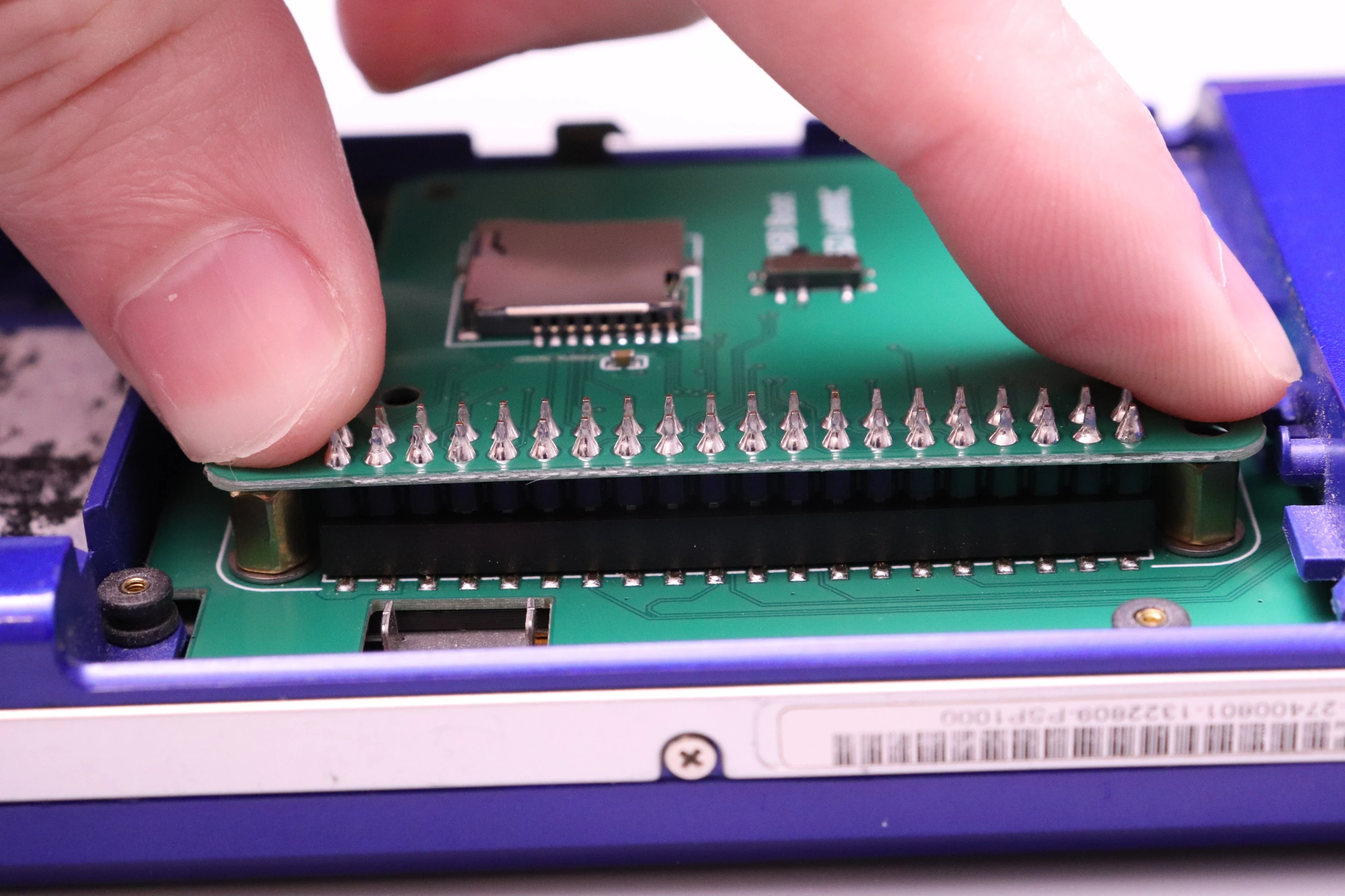
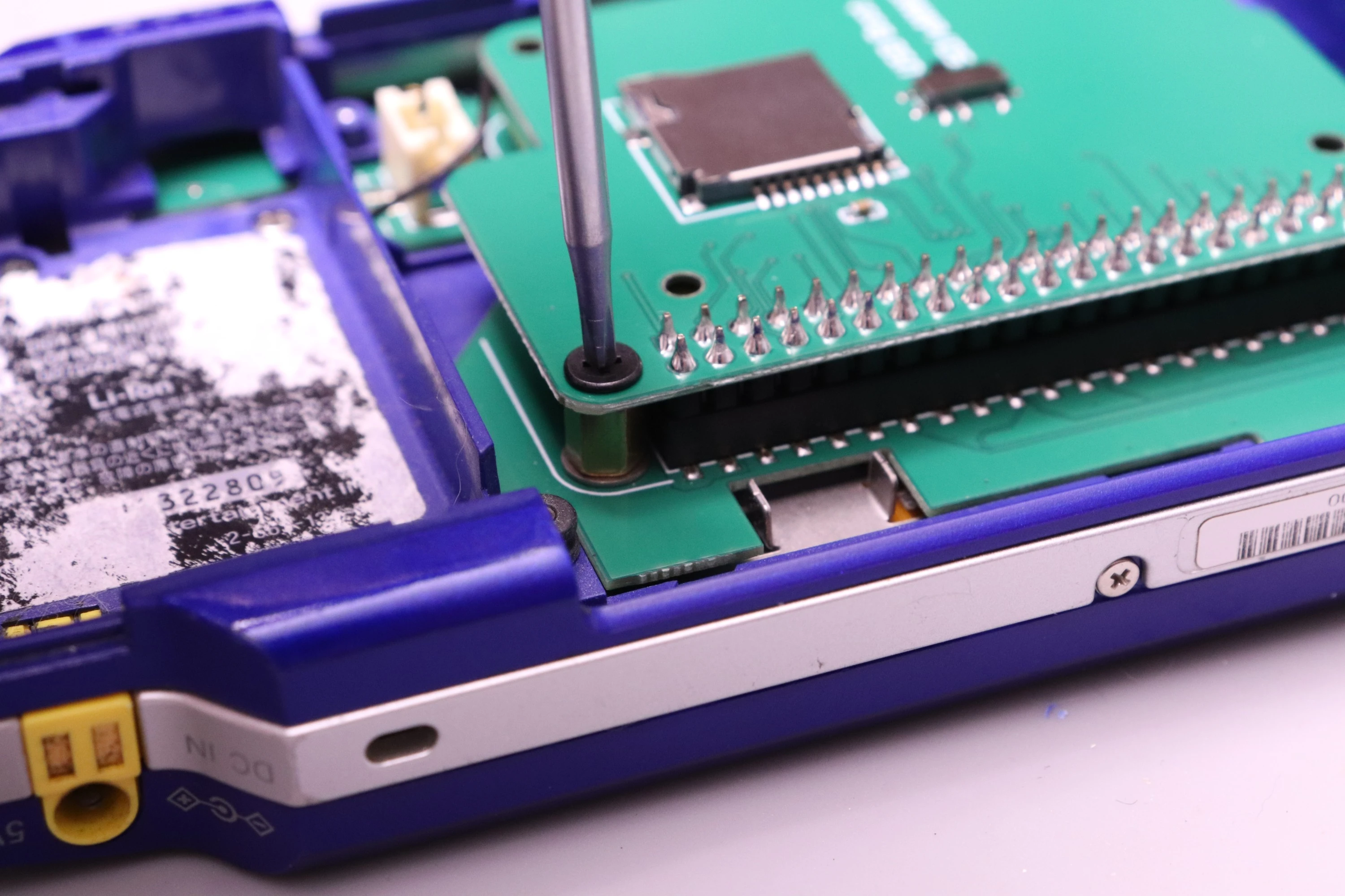
Now install the CM4 Carrier into the PSPi 6 board. Line the 40 header pins up with the female connector on the PSPi, and press down. Rocking the board a bit while pressing down will make the process easier. Keep pushing it down until it meets up with the brass standoffs.
 |
 |
 |
Then install the two screws.
 |
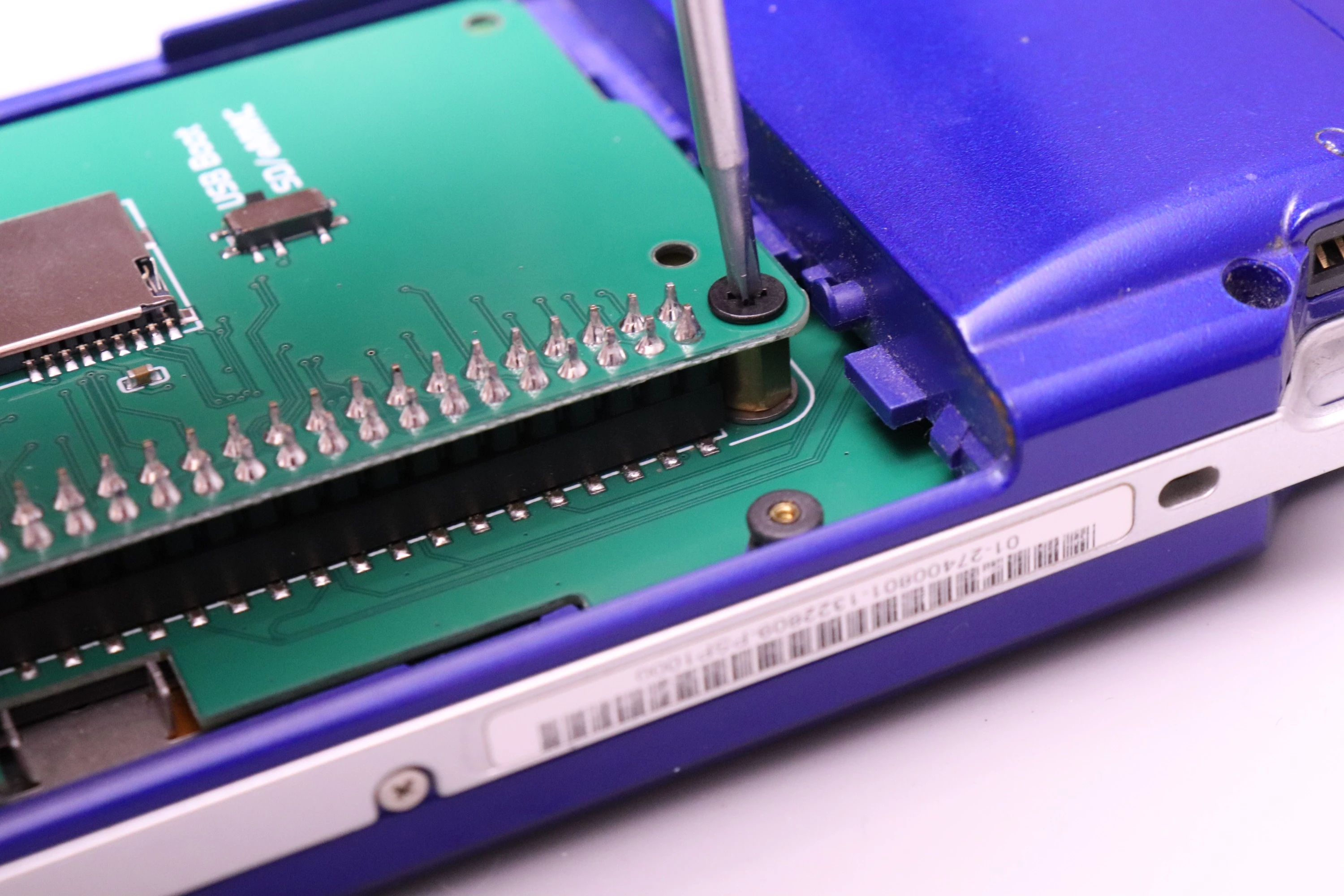 |
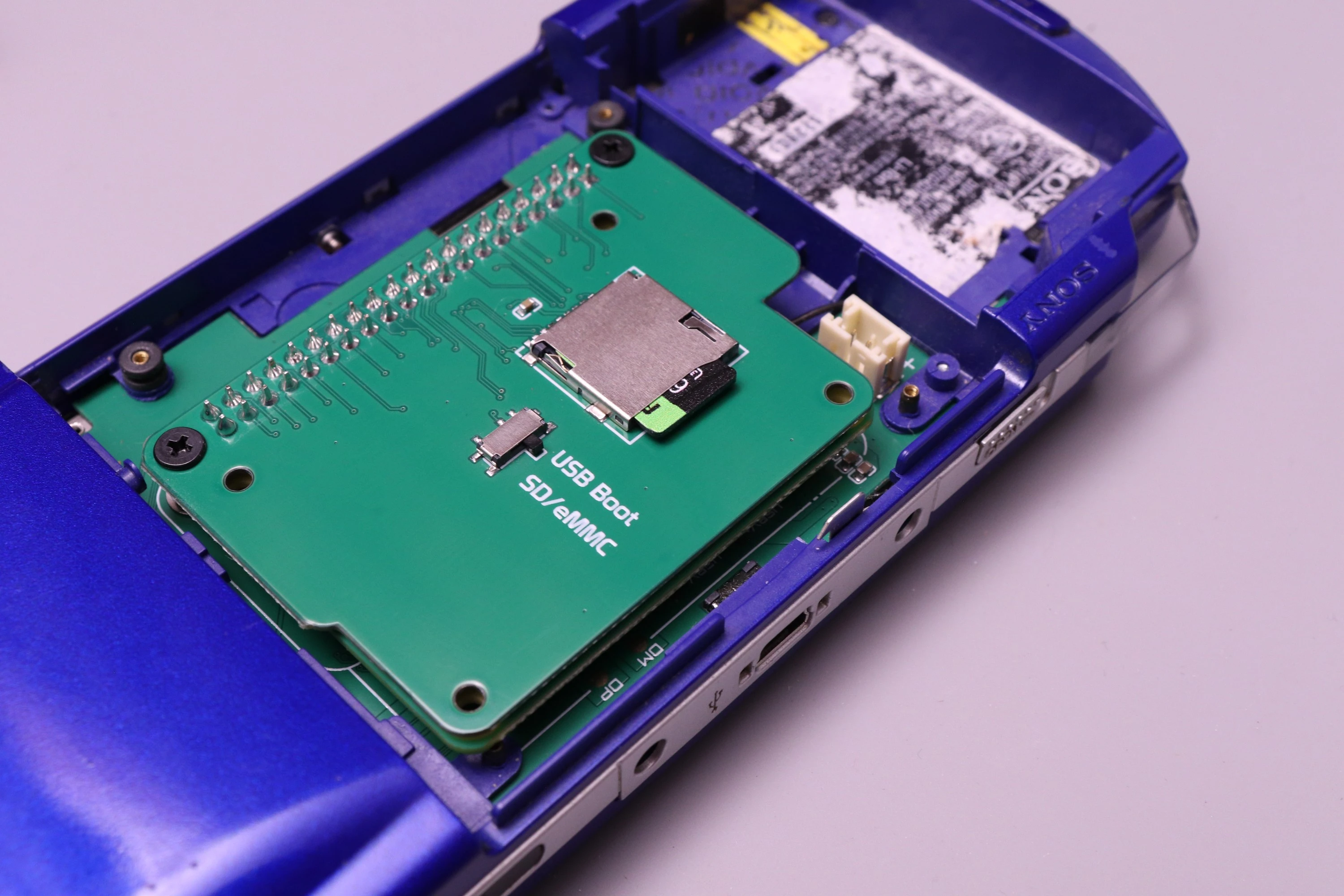
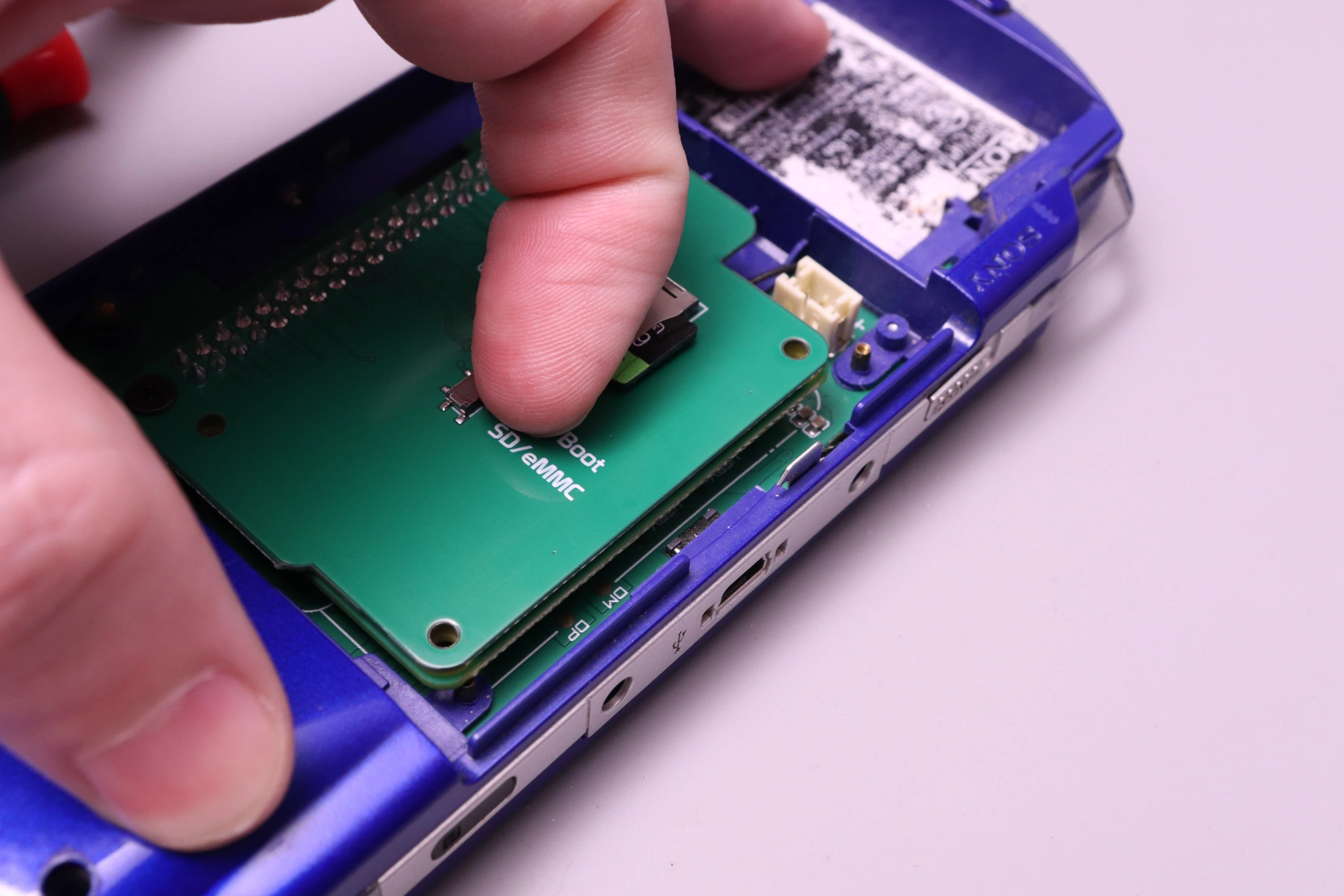
Now install the SD card (if you're using a CM4 Lite) and make sure the boot selection switch is set to SD/eMMC Boot
 |
 |
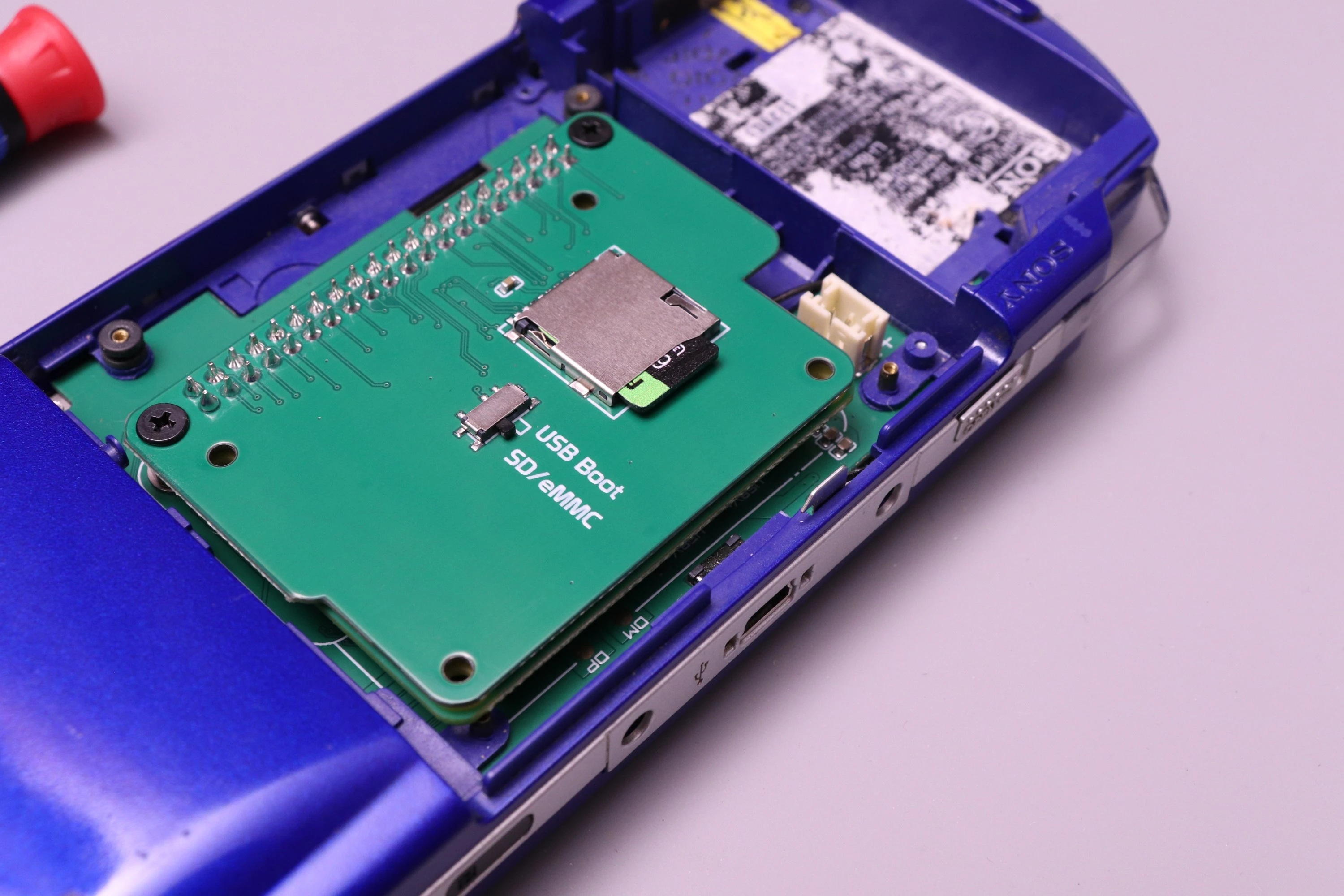 |
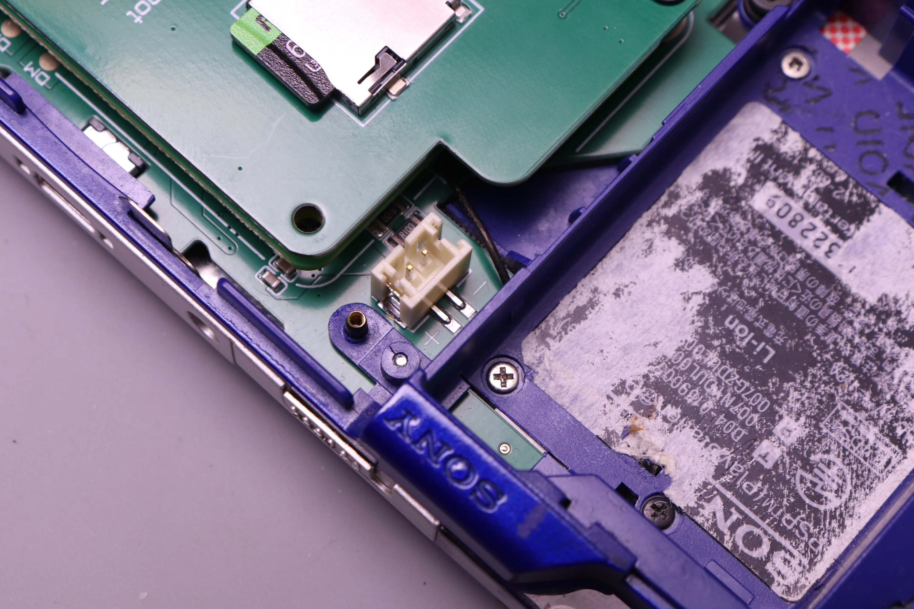
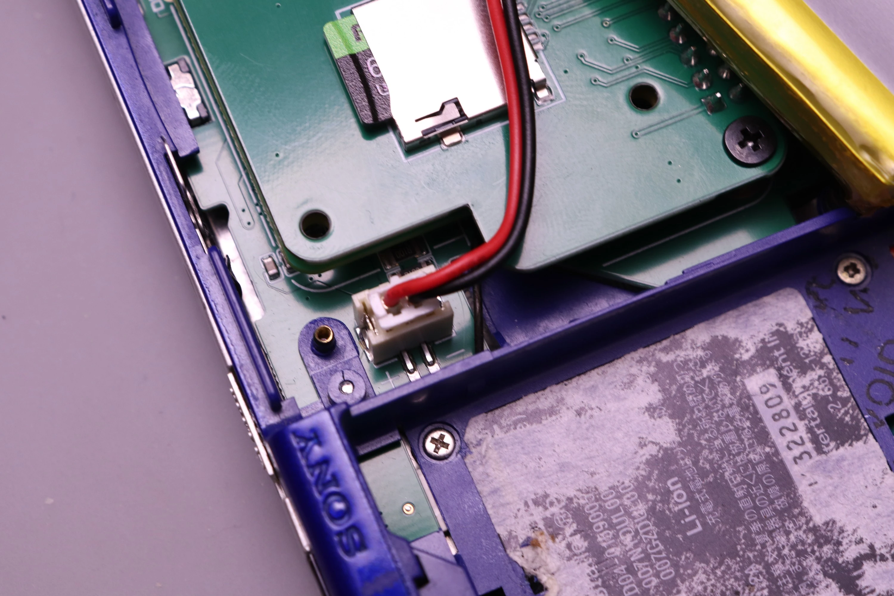
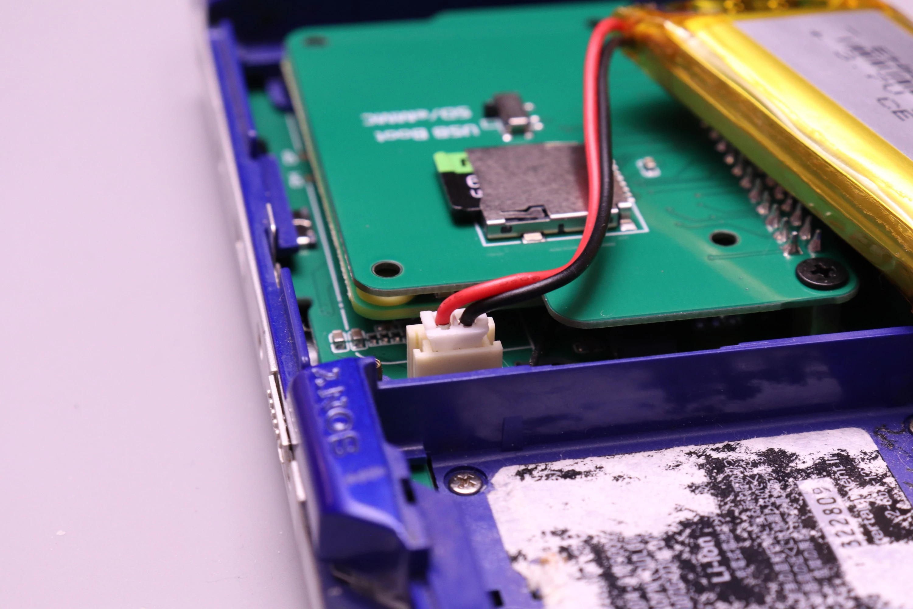
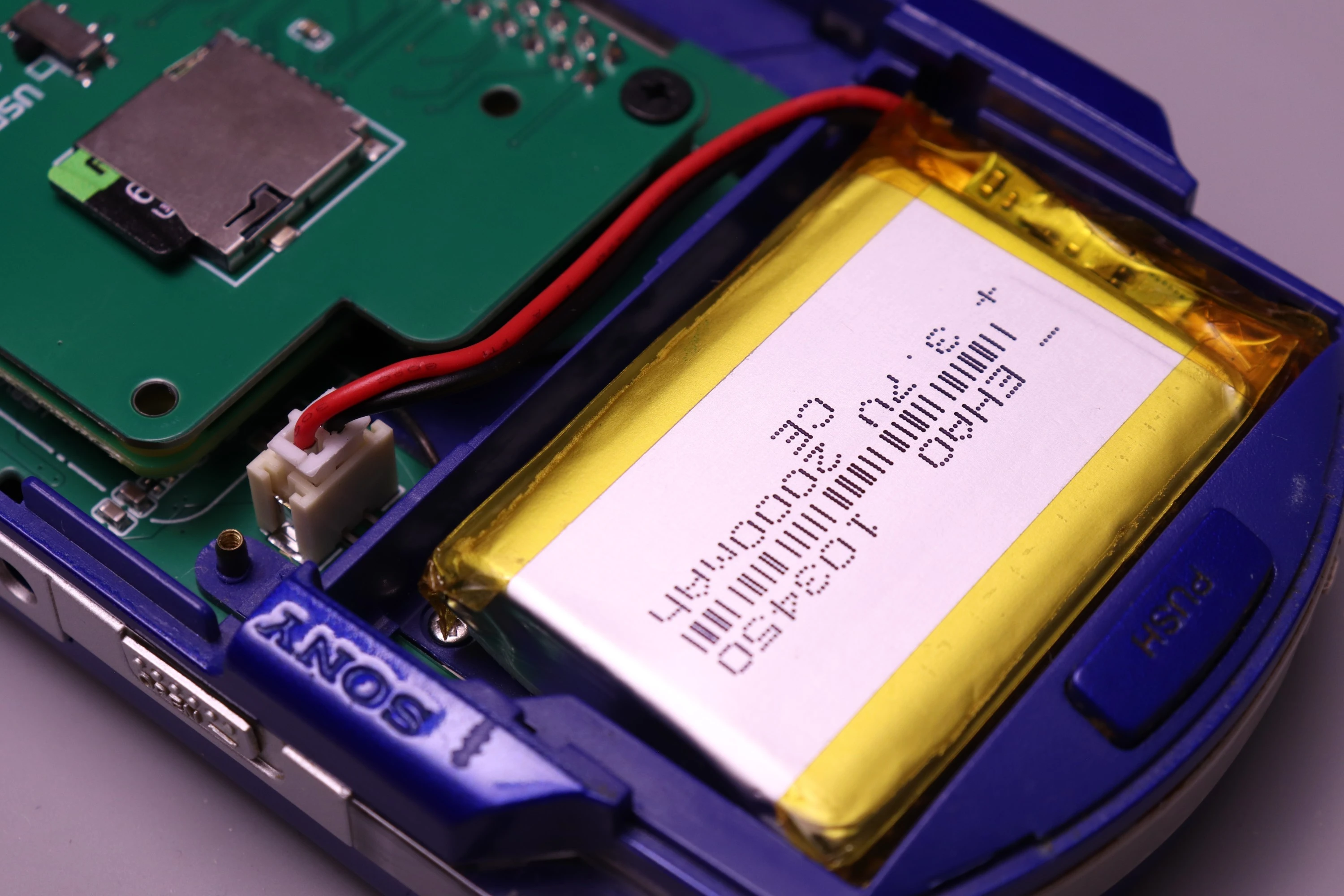
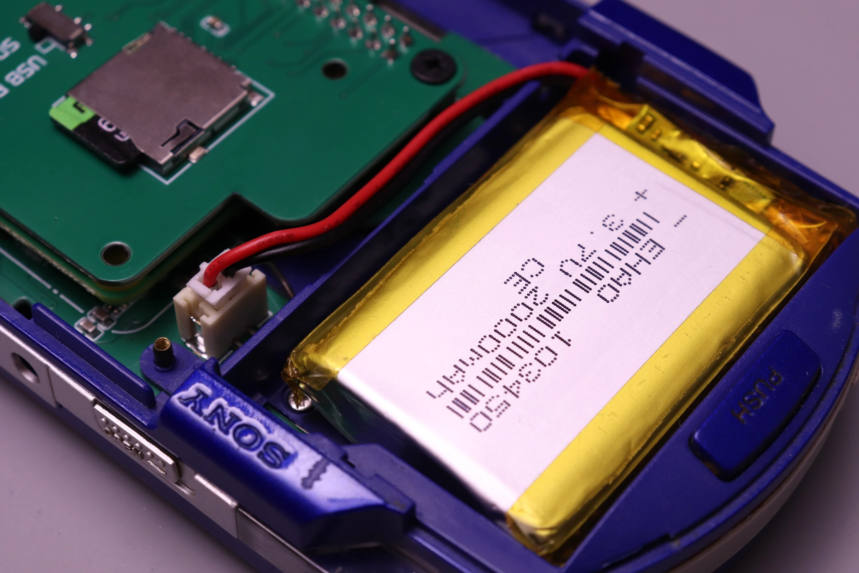
Connect a 2000mAh LiPo battery with a JST PH 2.0mm connector to the battery port on the PSPi 6 board. The board is clearly marked with + and - symbols to indicate correct polarity. Ensure the battery's red wire connects to + and the black wire connects to -.
Double-check polarity before connecting - incorrect polarity can damage the PSPi 6 board.
 |
 |
 |
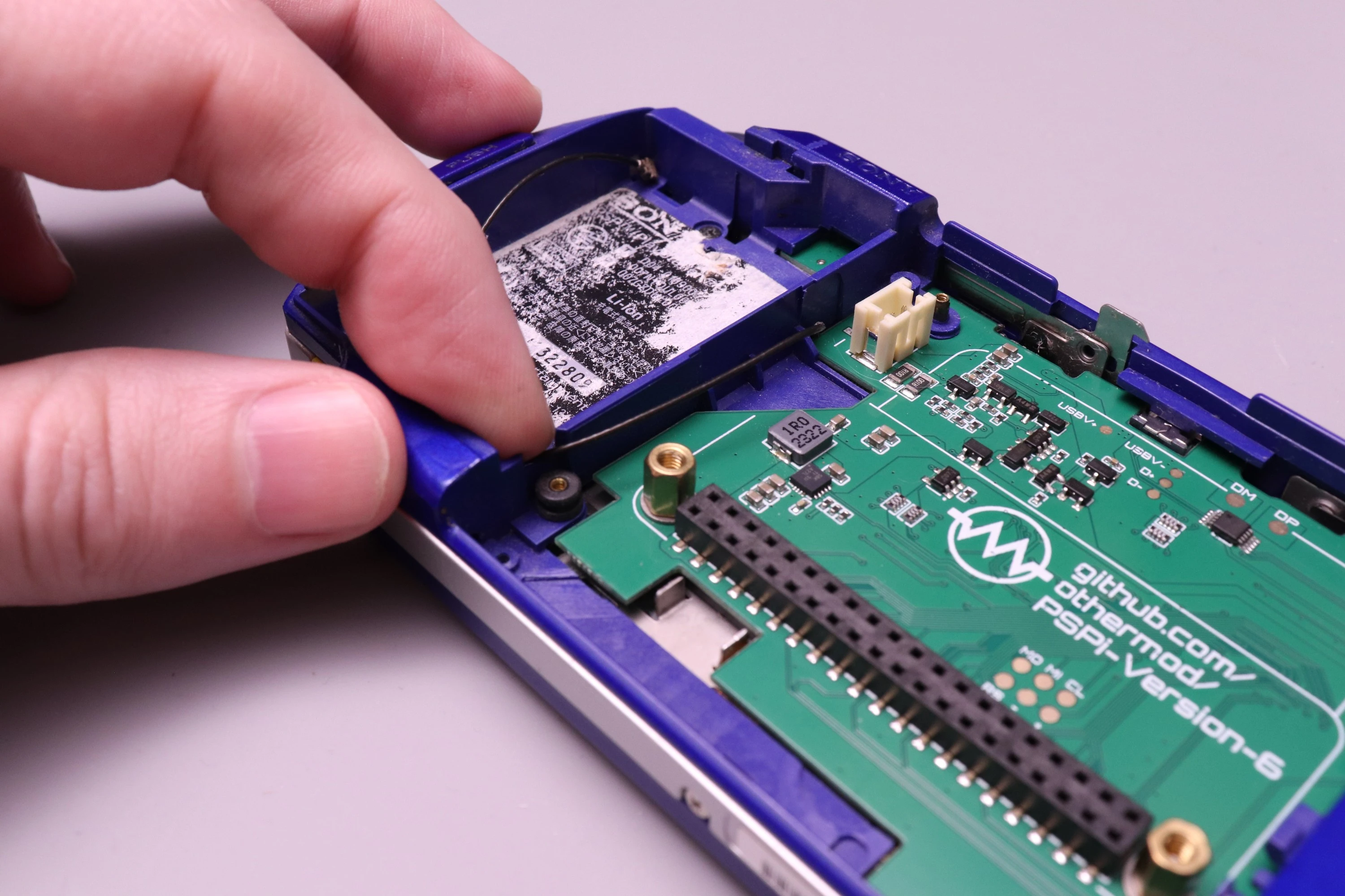
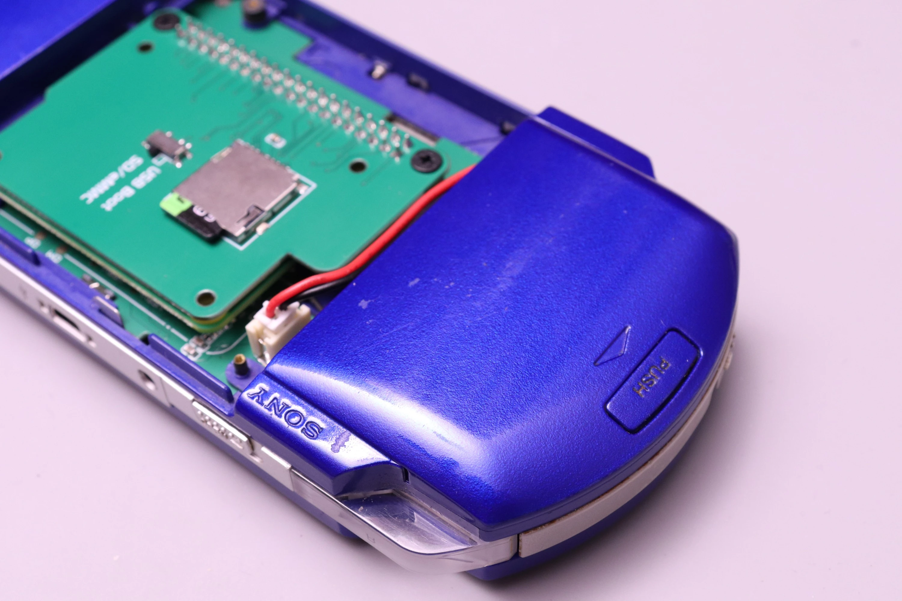
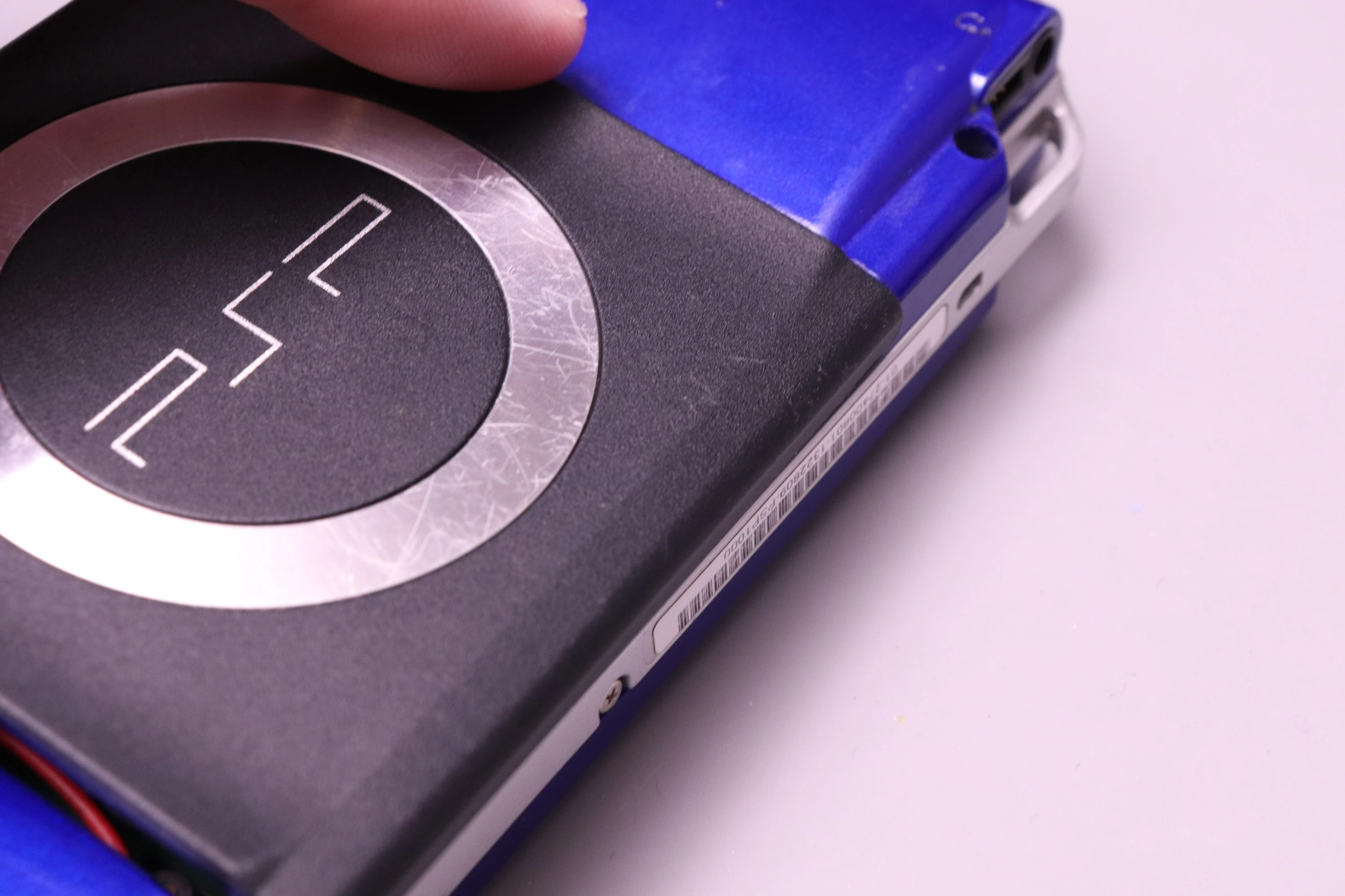
Then set the battery into the battery compartment and install the cover.
 |
 |
 |
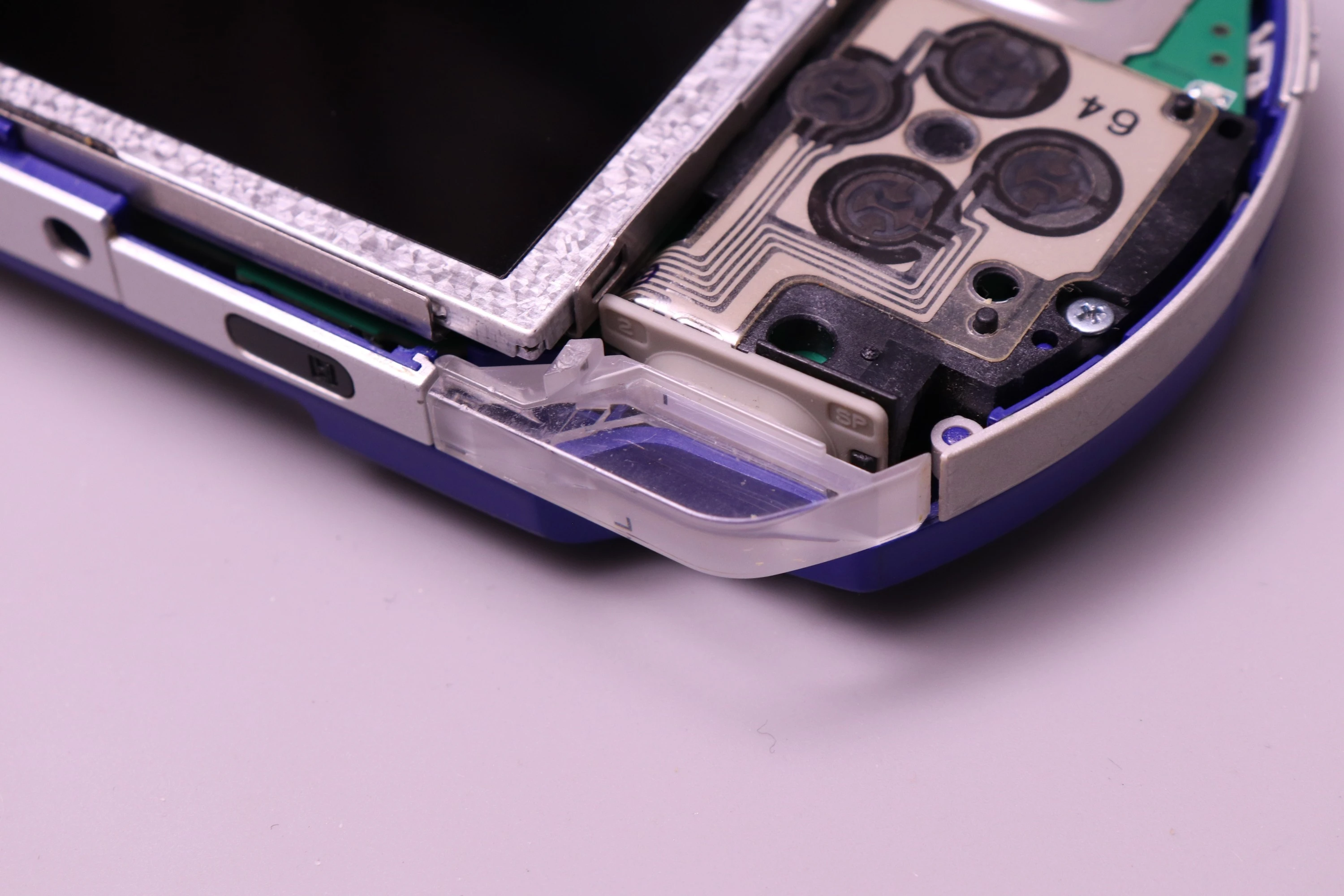
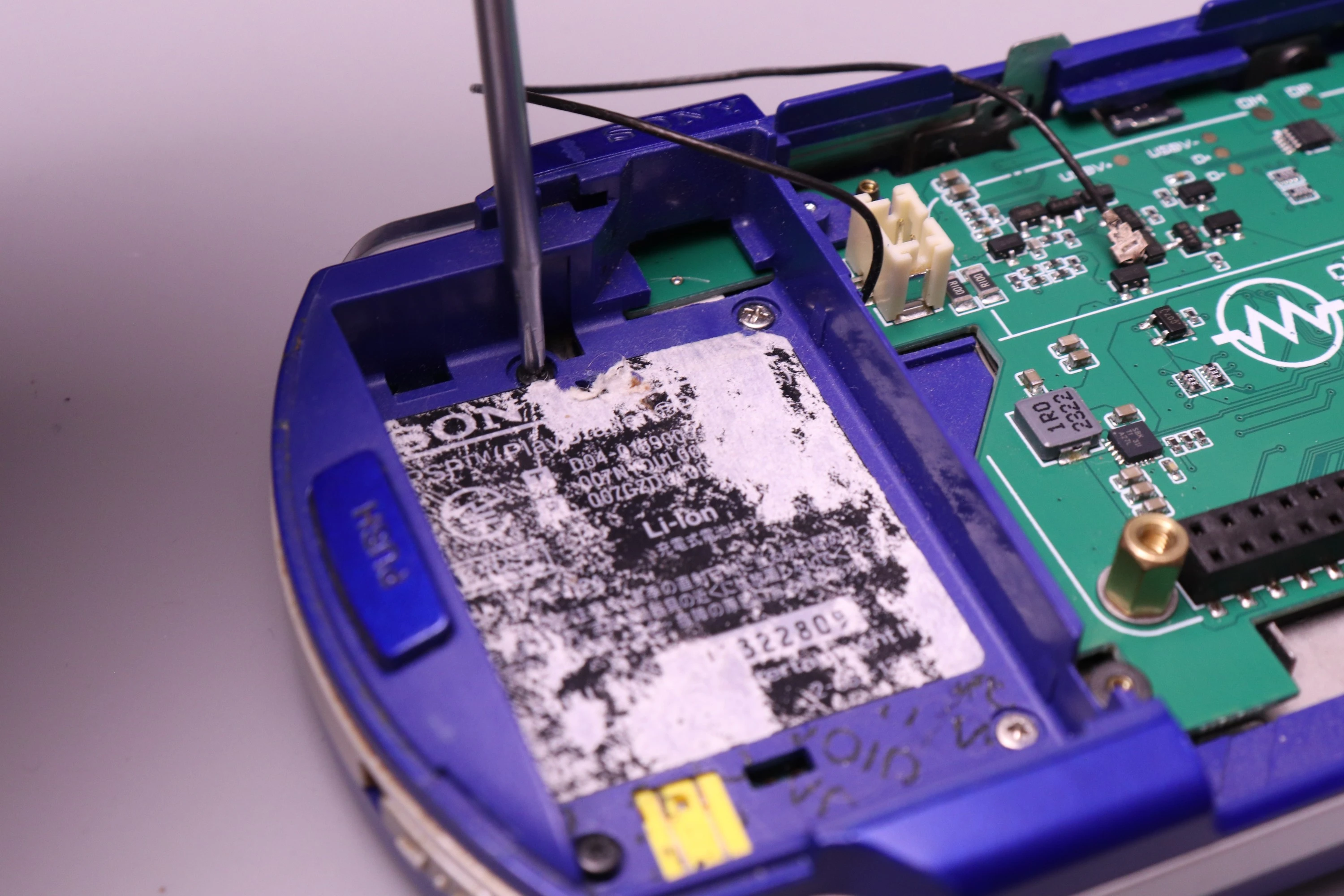
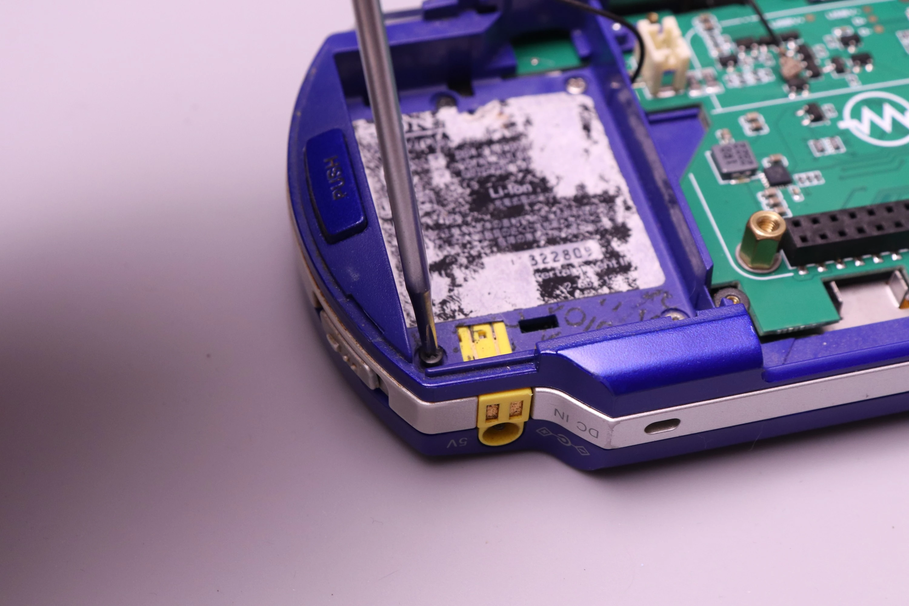
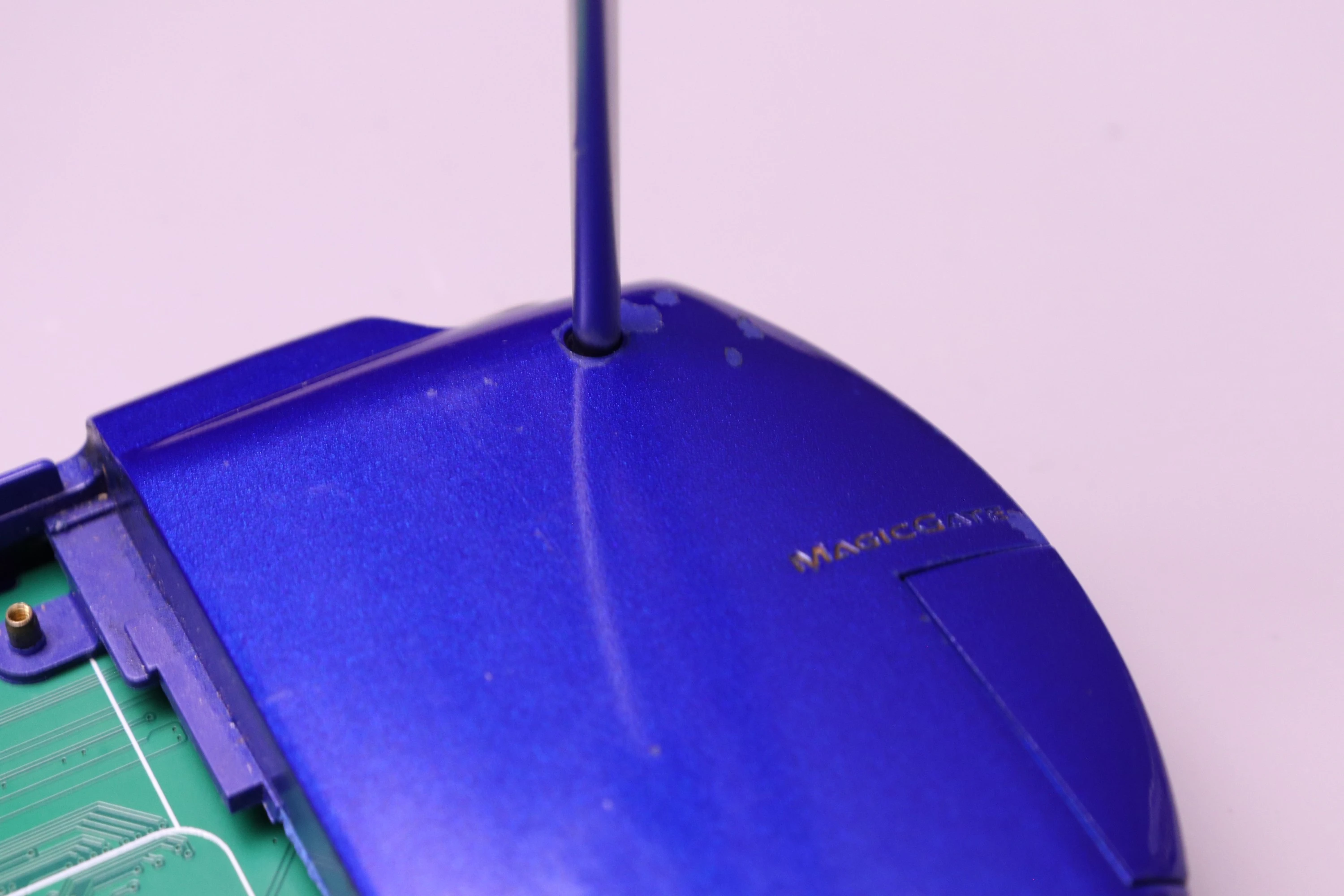
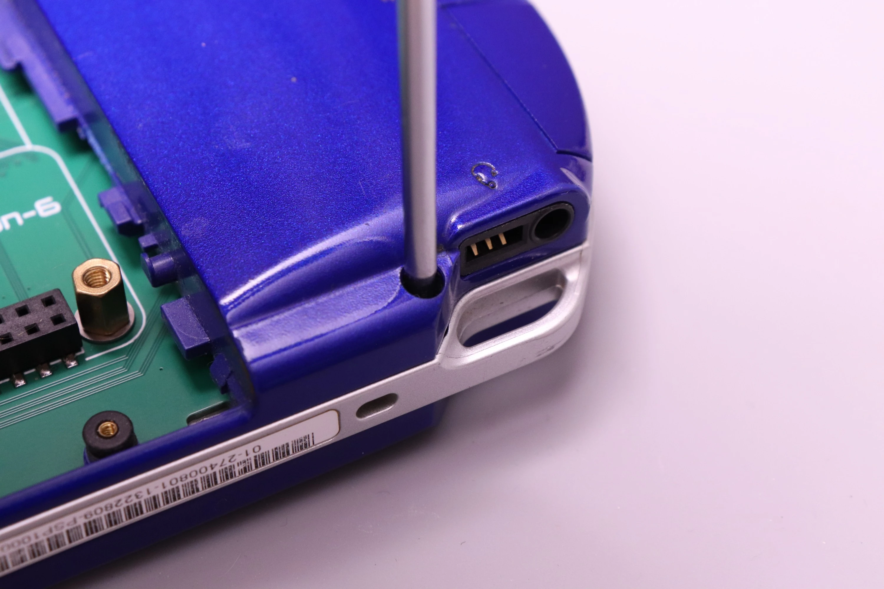
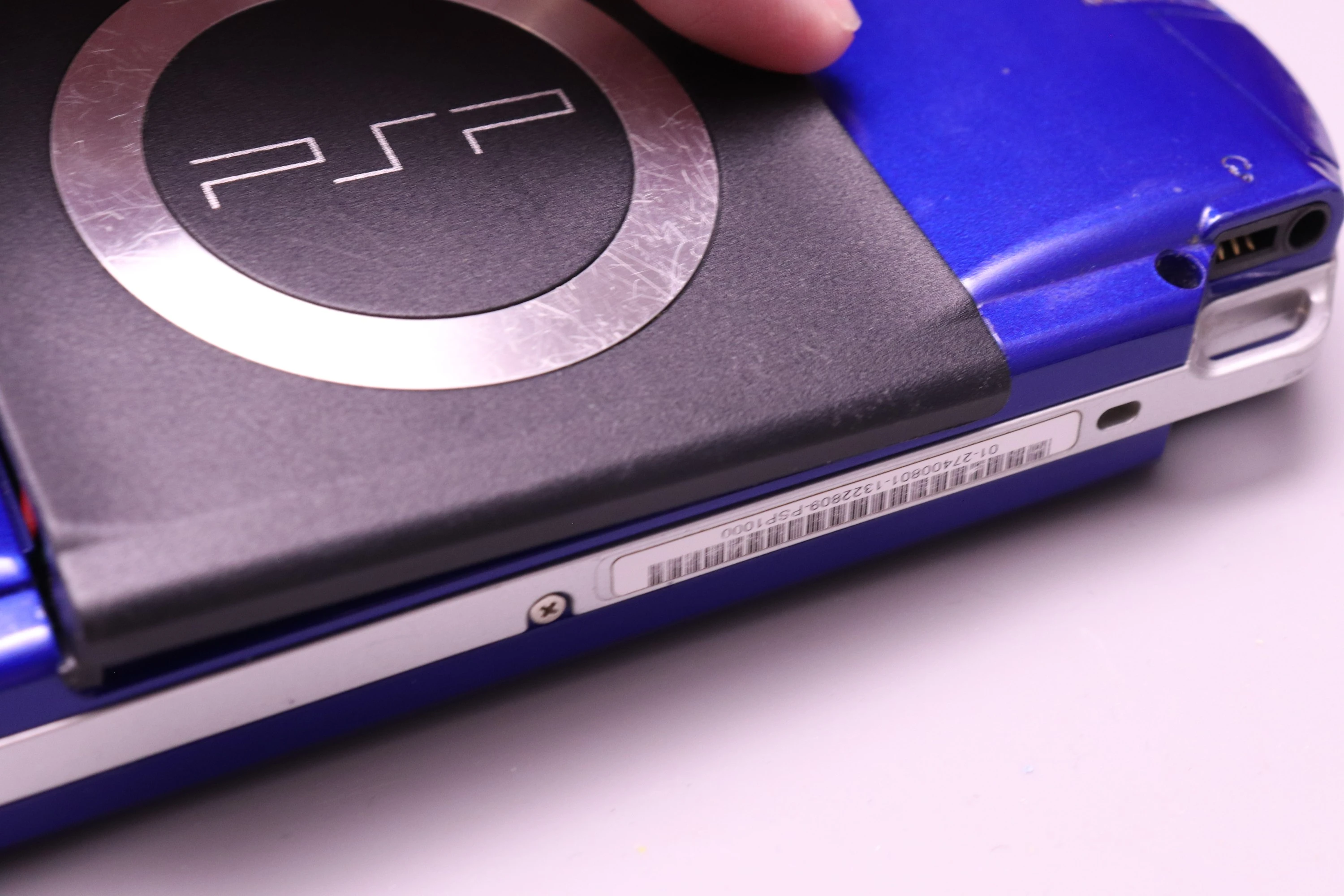
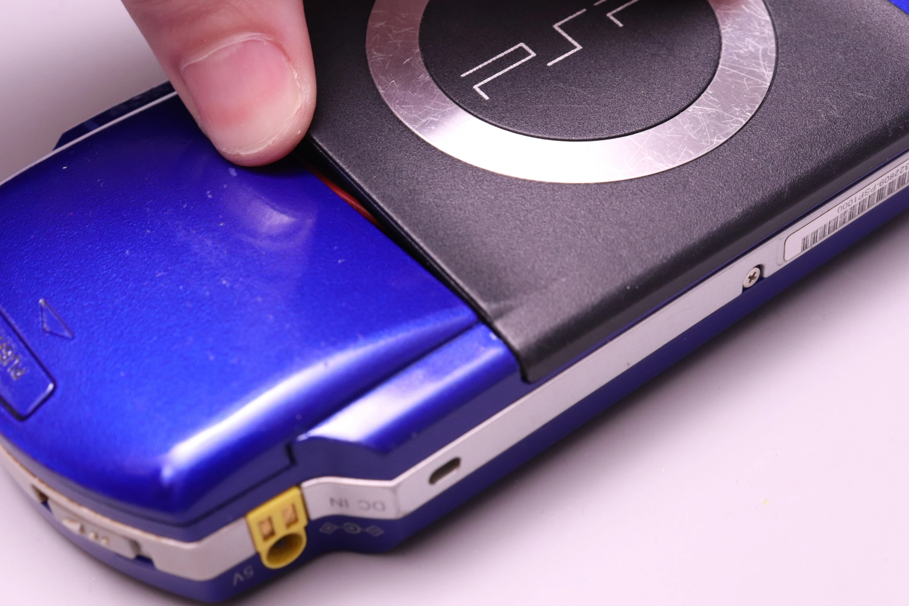
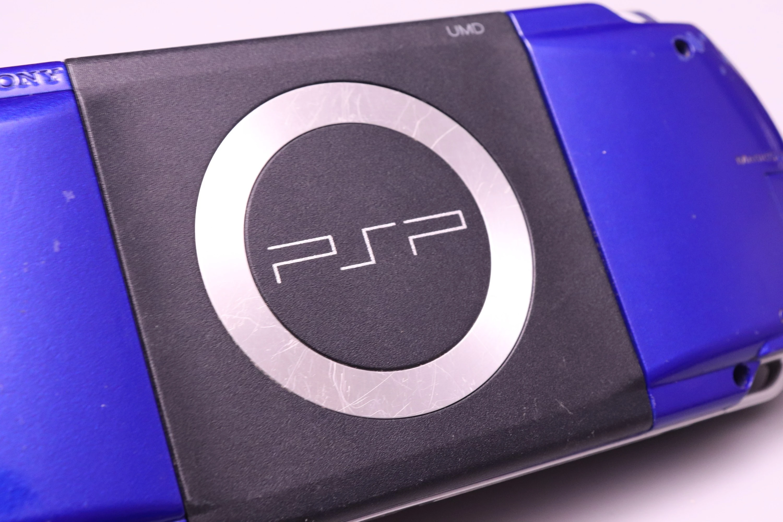
Finally, install the UMD Door. Start with the side closest to the headphone jack. Set it into the notch, and then rock the other side into place and let it pop into position.
 |
 |
 |
 |
Tito did an amazing job in his video, showing both the disassembly of the PSP and assembly of the PSPi kit.
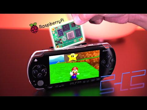
My earlier video also shows a quick installation of an earlier prototype.
MoBS also made a video showing the installation process, and he has a few other PSPi videos on his channel. Some of them show a process that differs slightly from what is needed currently because the PCB design changed slightly after the prototypes were made.