7. ATmega Firmware
The ATmega8 handles hardware interfacing on the PSPi 6 -- reading buttons, managing power, and controlling the backlight. All boards sold by othermod.com come with the firmware and bootloader pre-flashed and ready to use.
Boards running PCB version 1.5 or newer sold on from othermod.com have the bootloader installed and can update firmware without any wiring using the firmware update image.
- A MicroSD card
- The latest PSPi 6 Firmware Update image
- Flash the firmware update image to a MicroSD card.
- Shut the device down completely.
- Insert the MicroSD card.
- Hold the display button and power on. Keep holding for one full second until the WiFi LED begins blinking -- this puts the ATmega into bootloader mode.
- Wait for the update to complete. The process runs automatically.
- When the WiFi LED switches to fast blinking, the firmware has been verified and the update is complete. The device will power off on its own shortly after.
- Swap back to your regular MicroSD card.
If you have a self-manufactured board or a PCB version older than 1.5, the bootloader is not yet present and the ATmega must be flashed manually over SPI using avrdude. This requires physical access to the SPI test points on the board.
After completing this process, the board will have the bootloader installed and can receive future firmware updates using the method above -- no wiring required.
- Raspberry Pi or Arduino
- avrdude (
sudo apt install avrdude) - Wires or a pogo pin rig
You will need to connect to six test points on the PSPi board:

- 🔴 VCC
- ⚫ GND (use a ground pin on the 40-pin header on PCB versions earlier than 1.2)
- 🟢 Clock
- 🟠 MISO
- 🔵 MOSI
- 🟡 Reset
Connect the PSPi board to your Raspberry Pi GPIO pins:
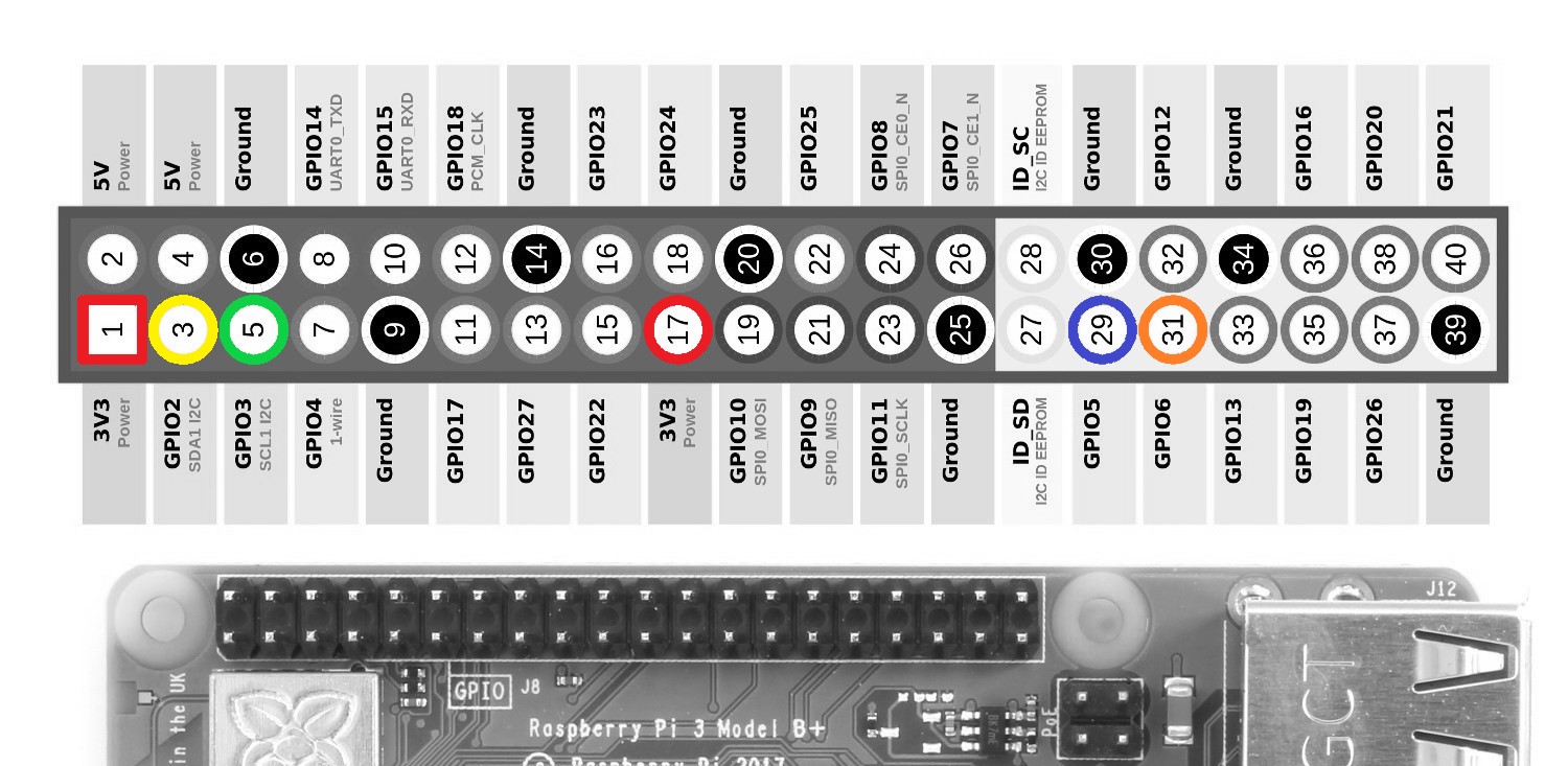
- 🔴 VCC to 3.3V (Pin 1 or 17)
- ⚫ GND to any GND pin (e.g. Pin 6)
- 🟢 Clock to GPIO3
- 🟠 MISO to GPIO6
- 🔵 MOSI to GPIO5
- 🟡 Reset to GPIO2
Configure the linuxgpio programmer in /etc/avrdude.conf (search for the linuxgpio entry, uncomment it, and set the pin numbers to match):
programmer
  id    = "linuxgpio";
  desc  = "Use the Linux sysfs interface to bitbang GPIO lines";
  type  = "linuxgpio";
  reset = 2;
  sck   = 3;
  mosi  = 5;
  miso  = 6;
;
Then flash the fuses and firmware together:
sudo avrdude -c linuxgpio -p m8 -U lfuse:w:0xA4:m -U hfuse:w:0xDA:m -U flash:w:combined.hex:i