Hardware
The hardware consists primarily of PVC pipes with incorporated 3D printed parts. 3 pipes are used in the final set up, three 120mm diameter and one 100mm tube. The 120mm first acts as an input tube and houses a small switch to detect the entry of glass bottles. The next houses the pi, camera, PCB and LCD screen and is where the classification takes place. The third acts as a housing for the 3D printed setup required to allow the motor to actuate the chute. The chute is created from the 100mm pipe and is actuated by the motor in order to direct glass to its appropriate location. Photos of the full setup are shown below. PICTURES OF SETUP
The most critical portions of this setup are enclosed in the case on the middle pipe. Here the Pi, PCB and LCD are held in the back portion and the camera and LEDs with associated PCB are held in the inner portion. The LEDs cast white light into the white interior of the tube and function to bring the standard colour values too zero to aid in colour classification. This portion of the set up is shown in more detail below.
The majority of the complexity in the assembly is embedded below the chute, this region enables the motor to turn the chute. This portion is where the majority of 3D printed pieces are embedded and is visualised here.
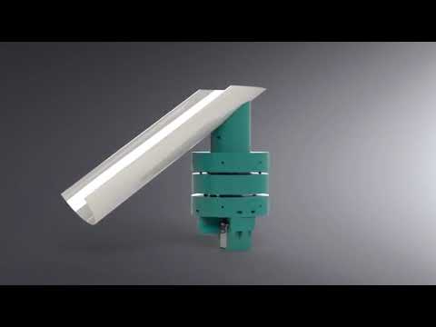
As can be seen there are 3 discs incorporated into the bottom of the pipe. The central disc extends up and slots around the output chute. The two external discs act to hold the central rotating portion in place, 3D printed bearings are included between each for ease of rotation. The central portion is actuated by a shaft which is controlled by the servo motor. This is held in a casing beneath the lowest disc. The files for each of these parts are included in the folder 3D Models. These files are print ready and a full assembly guide is also included below for anyone looking to recreate this project.
The STL files of the 3D models can be found in the hardware/3DModels/STL Files folder.
This project makes use of twp printed circuit boards manufactured at Glasgow University. If attempting to recreate this project it is strongly advised to make use of such a board in order to ... The main PCB brings everything together and inserts directly on to the raspberry Pi's inbuilt pins. The design for this board is shown below.


The second PCB is far simpler and used to power the surface mounted LEDs, it is designed around the camera in order to obtain an even light distribution and not negatively impact classification. Again the schematic is shown below.


All the files required to have these PCBs produced can be found in the hardware/PCB folder.