Home
Glassify is a low cost, easily integrated real time colour sorting system. Its primary purpose is to sort glass bottles of different colours to aid in the recycling process. Despite this it could be easily optimised for other colour sorting applications.
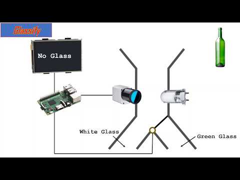
The UK alone recycles 752,000 tonnes of glass each year. This saves around 237 million kilograms of CO2 from being released into the atmosphere.
The process of making glass involves melting sand, soda ash and limestone at 1500oC, the use of recycled glass means the energy used to extract these materials can be saved. As a result recycled glass leads to a 20% reduction in air pollution and a 50% reduction in water pollution compared to making glass from scratch. For every tonne of glass recycled 1.2 tonnes of these materials is saved.
The level of waste recycled in the UK is substantially lower than the level of waste placed into recycling bins. 25% of waste put into recycled bins ends up in landfill, a primary cause for this is contamination.
Glass recycling is often overlooked when it comes to contamination in recycling however this should not be the case. Based on the country or even county you live in the glass recycling systems can vary hugely. Some regions require the user to separate by colour whilst others rely on this being carried out at a later stage.
Glass can be 100% recycled with no loss in quality. Glasses ability to be recycled without a drop in contamination is heavily dependant on a lack of contamination. This is because the variation of colour across glass is brought about through the addition of different impurities. Brown (amber) glass is created using carbon nickle and sulfer. These protect the contents from sunlight. Green glass is made using copper, iron and chromium. Clear glass is simply pure sand and limestone. By introducing impurities from a separate colour of glass into the stream the quality of the glass will swiftly diminish.
We propose a simple solution that could be integrated at any level in the recycling chain. Glassify is an incredibly low cost system which rapidly sorts glass by colour.
The hardware consists primarily of PVC pipes with incorporated 3D printed parts. 3 pipes are used in the final set up, three 120mm diameter and one 100mm tube. The 120mm first acts as an input tube and houses a small switch to detect the entry of glass bottles. The next houses the pi, camera, PCB and LCD screen and is where the classification takes place. The third acts as a housing for the 3D printed setup required to allow the motor to actuate the chute. The chute is created from the 100mm pipe and is actuated by the motor in order to direct glass to its appropriate location. Photos of the full setup are shown below. PICTURES OF SETUP
The most critical portions of this setup are enclosed in the case on the middle pipe. Here the Pi, PCB and LCD are held in the back portion and the camera and LEDs with associated PCB are held in the inner portion. The LEDs cast white light into the white interior of the tube and function to bring the standard colour values too zero to aid in colour classification. This portion of the set up is shown in more detail below.
The majority of the complexity in the assembly is embedded below the chute, this region enables the motor to turn the chute. This portion is where the majority of 3D printed pieces are embedded and is visualised here.
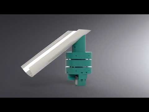
As can be seen there are 3 discs incorporated into the bottom of the pipe. The central disc extends up and slots around the output chute. The two external discs act to hold the central rotating portion in place, 3D printed bearings are included between each for ease of rotation. The central portion is actuated by a shaft which is controlled by the servo motor. This is held in a casing beneath the lowest disc. The files for each of these parts are included in the folder 3D Models. These files are print ready and a full assembly guide is also included below for anyone looking to recreate this project.
ASSEMBLY GUIDE
This project makes use of twp printed circuit boards manufactured at Glasgow University. If attempting to recreate this project it is strongly advised to make use of such a board in order to ... The main PCB brings everything together and inserts directly on to the raspberry Pi's inbuilt pins. The design for this board is shown below.


The second PCB is far simpler and used to power the surface mounted LEDs, it is designed around the camera in order to obtain an even light distribution and not negatively impact classification. Again the schematic is shown below.


All the files required to have either of these PCBs produced can be found in the hardware/PCB folder of this repository.
Our classification system utilises OpenCV to separate colours. Images of masked classified bottles.
The script itself consists of several threads. A switch at the top of the pipe is polled to determine when a bottle enters the system. When this is activated the LEDs around the camera turn on and the camera begins capturing and classifying images, this continues until a classification is made. At this point the motor reacts to the classified result. SEQUENCE DIAGRAM
Our team consists of Ross Crawford, Reuben Docea and Gergely Pogany, 3 Biomedical engineering Meng students from Glasgow University. Work has been distributed throughout the team in order to efficiently make use of the time available to us.
The original theoretical design process was carried out collectively. After this tasks were distributed to speed up production.
Ross –
- Modelling:
- Top disk
- Bottom disk
- Shaft
- Gears
- Switch Holder
Reuben –
- 3D printing aficionado
- Modelling:
- Central portion
- Servo Casing
- Bearings
- Pi Casing
- Stand
Gergerly –
- PCB design
- PCB soldering
Ross – Switch Polling and generating final script
Reuben – Classification and communication between threads
Gergerly – Motor, LCD and Menu
Below is a Gantt chart detailing the intended schedule for this project. This chart begins on February 15th as prior to this an alternative project was being pursued which had to be abandoned due to hardware limitations.
Due to the nature of the task we are undertaking the majority of issues are unpredictable. As a result aside from the pre-set plan and task distribution further aims and work was designated on a day by day basis during brief agile meetings each morning.
- PVC 120mm x 35mm Piping x3
- PVC 100mm x 35mm Piping
- Nuts (M4, M3 and M2)
- Bolts (M4, M3 and M2)
- 3D printer filament – PLA and PLTG
- Servomotor
- LCD screen (1602A)
- Raspberry Pi 3b (or other)
- Ribbon Cabling
- Solder
- Surface Mounted White LEDs x8
- 3D printer
- Small saw or good scissors
- Electric drill
- PCB manufacture method (optional but advised)
- Soldering equipment
Our social media presence focussed primarily on facebook and instagram as they allowed us to easily share our material with those it might interest through the use of hashtags and posting to groups.
In order to create the code to run Glassify the following libraries were used.