Realsense Viewer Manual
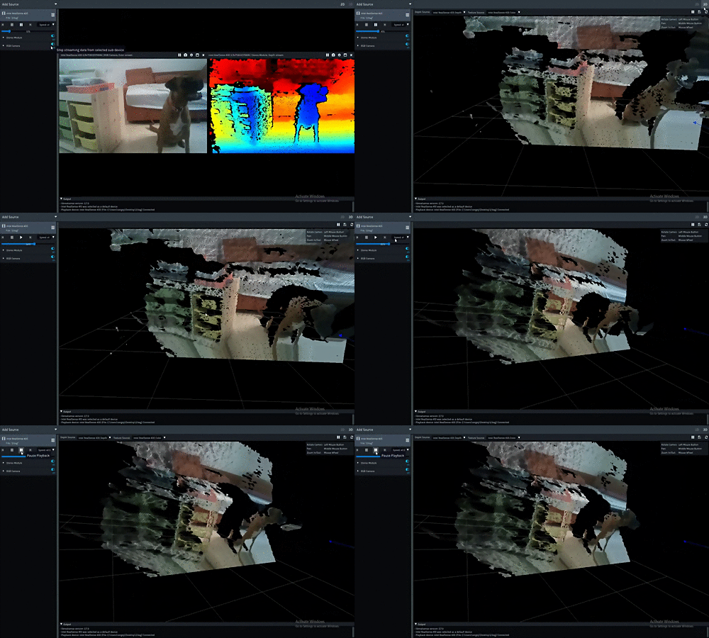
RealSense Viewer is the flagship tool providing access to most camera functionality through simple, cross-platform UI. The tool offers:
- Streaming from multiple RealSense devices at the same time
- Exploring pointcloud data in realtime or by exporting to file
- Recording RealSense data as well as playback of recorded files (Please refer to Record and Playback for further information)
- Access to most camera specific controls, including 3D-generation ASIC registers when available
This readme is organized as a reference: if you are looking for a specific control, button, or option, use the Table of Contents below to jump straight to it.
- Implementation Notes
- Command Line Parameters
- Global Toolbar & Menus
- Device Panel
- Sensor Controls
-
Sensor Options Reference
- Color / RGB image controls
- Exposure & gain controls
- Laser, emitter & illumination controls
- Depth processing & filtering options
- Depth range, units & calibration options
- Visual presets & hardware configuration
- HDR options
- Motion module (IMU) controls
- Safety camera controls
- Diagnostics / read-only telemetry
- Deprecated options
- Post-Processing & Embedded Filters
- Advanced Mode
- On-Chip / Self Calibration
- 2D Stream View
- 3D Point-Cloud Viewer
- Measurement Tool
- Recording & Playback
- Keyboard Shortcuts
You can get RealSense Viewer in form of a binary package on Windows and Linux, or build it from source alongside the rest of the library. The viewer is designed to be lightweight, requiring only a handful of embeded dependencies. Cross-platform UI is a combination of raw OpenGL calls, GLFW for cross-platform window and event management, and IMGUI for the interface elements. Please see COPYING for full list of attributions.
| Flag | Description |
|---|---|
--debug |
Turn on LibRS debug logs to console, regardless of other settings |
--sw-only |
Show only software devices: playback, DDS, etc. -- but not USB/HID/etc. |
The Add Source button (top-left) opens a popup listing every detected-but-not-yet-added device, plus a Load Recorded Sequence entry that opens a file dialog (filtered to *.bag / *.db3) for opening a previously recorded file for playback. Selecting a device row adds it to the current view.
The top-right toolbar has two view-mode buttons:
- 2D — tiled per-stream view. Each stream gets its own tile with a small per-tile toolbar (see 2D Stream View).
- 3D — point-cloud view (see 3D Point-Cloud Viewer).
Next to the view toggle, a rearrange-tiles icon (only enabled in 2D view) lets you drag one stream tile onto another to swap their positions; the arrangement is remembered per camera.
The gear icon opens the Settings menu; on non-embedded/fullscreen builds an additional power icon (tooltip "Exit the App") closes the application.
Clicking the gear icon opens a popup with:
-
Report Issue — opens a pre-filled GitHub issue (
github.com/realsenseai/librealsense/issues/new) including the connected device's information. - RS Store — opens the RealSense store website (https://store.realsenseai.com/).
- Settings — opens the Settings dialog.
- About — opens the About dialog (SDK version, license, and project links).
The Settings dialog has up to four tabs:
Playback & Record
- Radio buttons: Select filename automatically / Ask me every time — controls whether recordings get an auto-generated timestamped filename or prompt with a save dialog.
- Default recording folder — where auto-named recordings are written.
- ROS-bag compression radio buttons: Always Compress / Never Compress / Use device defaults.
Performance
- Font Samples / Font Size sliders.
- Use GLSL for Rendering / Use GLSL for Processing checkboxes (GLSL is required for some 3D features such as diffuse-lit shading and the Measurement tool).
- Enable Multisample Anti-Aliasing (MSAA) checkbox + MSAA Samples slider.
- Show Application FPS (rendering FPS) checkbox.
- Enable VSync checkbox.
- Fullscreen (F8) checkbox.
- Show Skybox in 3D View checkbox.
- Perform Occlusion Invalidation checkbox.
General
- Units of Measurement combo — Imperial System / Metric System (affects distances shown by the Measurement Tool and elsewhere).
- Output librealsense log to console / Output librealsense log to file checkboxes (with log file path and Minimal log severity combo).
- Commands.xml Path — path to the XML file describing raw hardware commands.
- FW logs XML file — path to the firmware-log-definitions XML, with a file-picker button.
- Restore Defaults, Export Settings, Import Settings buttons.
- Allow partial device initialization checkbox (takes effect after restart).
- Enable DDS checkbox + Domain ID field (takes effect after restart).
Updates (only in builds with update-checking enabled)
- SW/FW Updates From Server — Official Server / Custom Server radio buttons, with a text field for the custom URL.
The dialog closes with OK (save and close), Apply (save, stay open), or Cancel (discard changes).
Each connected device's panel header shows a row of icon buttons:
| Icon | Label | Behavior |
|---|---|---|
| Circle / stop | Record / Stop | Starts or stops recording this device to a .bag/.db3 file. See Recording & Playback. |
| Refresh | Sync | Toggles synchronization between this device's streams. |
| Info circle | Info | Shows/hides the device details panel (name, serial number, firmware version, USB type, etc.). |
| Bars | More | Opens the device "More" menu. |
| ✕ | (remove) | Removes the device from the current view (it can be re-added via Add Source). |
- Advanced Mode — toggles Advanced Mode (disabled while streaming; not available on D500 devices). Once enabled, the setting is stored in the device's flash and survives a camera reset.
- Hardware Reset — resets the device.
-
Switch to Dual-RGB Mode / Switch to Dedicated-RGB Mode — for D5x5 SKUs that support both a dedicated color sensor (3C) and dual-RGB configuration (2C); requires a hardware reset and the device re-enumerating under a different PID (
RS2_OPTION_SENSORS_CONFIG_MODE). -
Update Firmware — opens the firmware-update flow using a
.binimage you select. - Check For Updates — checks the update server for newer firmware/software.
- Update Unsigned Firmware... (D400 only) — flashes an unsigned/development firmware image.
- DDS Configuration (Ethernet-connected devices) — network configuration dialog.
- Auto-calibration entries — see On-Chip / Self Calibration.
Every physical sensor on the device (e.g. Stereo Module, RGB Camera, Motion Module, Tracking Module) gets its own collapsible section in the device panel.
At the top of each sensor's section:
- Resolution combo — sets the stream resolution.
- Frame Rate (FPS) combo — sets the streaming frame rate.
- Per-stream / per-format checkboxes — pick which streams (and pixel formats) to enable for that sensor.
These controls are locked while the sensor is streaming; hovering a locked control shows the tooltip "Can't modify while streaming".
Frequently used options are shown directly under Stream Selection without needing to open Controls: Visual preset, Emitter enabled, Enable auto exposure, and Auto Exposure Mode (depth auto-exposure mode).
Expanding a sensor's Controls section reveals every additional option the connected sensor and firmware report as supported (see the Sensor Options Reference below for what each one does), together with a text box hinting "Search controls...".
This is the fastest way to find a specific control by name: type any part of the control's name (case-insensitive) and the list live-filters to matching options only; clearing the box restores the full list. Color-image-specific options (Backlight compensation, Brightness, Contrast, Gamma, Hue, Saturation, Sharpness, White balance, Enable auto white balance) are always sorted to the end of the list.
If the device supports Advanced Mode, an Advanced Controls section appears below Controls; until Advanced Mode is turned on it shows a Turn on Advanced Mode button instead.
Each sensor section has an on/off toggle button that starts or stops streaming from that sensor. It is disabled (with an explanatory tooltip) when a dependent stream needs to be started first, or when a blocking embedded filter is enabled.
The options below are the raw sensor/firmware controls surfaced through rs2_option (include/librealsense2/h/rs_option.h). The Viewer displays a control's name and description exactly as reported by the connected sensor (rs2_get_option_name / rs2_get_option_description), so the exact set of controls you see depends on your specific camera model and firmware version — not every option below will appear on every device. Options are rendered as sliders, checkboxes, or dropdowns (for enumerated options) inside each sensor's Controls / Advanced Controls section, and can always be located with the Controls search box.
| Control | Description |
|---|---|
| Backlight compensation | Enable / disable color backlight compensation. |
| Brightness | Color image brightness. |
| Contrast | Color image contrast. |
| Gamma | Color image gamma setting. |
| Hue | Color image hue. |
| Saturation | Color image saturation setting. |
| Sharpness | Color image sharpness setting. |
| White balance | Manual white-balance value for the color image; setting it disables auto white balance. |
| Enable auto white balance | Enable / disable automatic white balance for the color image. |
| Power line frequency | Anti-flickering control: Off / 50 Hz / 60 Hz / Auto. |
| Digital gain | Depth digital gain: Auto / High / Low. Formerly named "Ambient light" (deprecated alias). |
| RGB TNR enabled | Enable / disable RGB Temporal Noise Reduction. |
| Sensors config mode | D5x5 only: 0 = dedicated color sensor (3C), 1 = dual RGB (2C). Requires a hardware reset; the device re-enumerates under a new PID. |
| Control | Description |
|---|---|
| Exposure | Controls the exposure time of the color camera. Setting any value disables auto exposure. |
| Gain | Color image gain. |
| Enable auto exposure | Enable / disable auto-exposure. |
| Auto exposure priority | Allows the sensor to dynamically adjust frame rate depending on lighting conditions. |
| Auto exposure converge step | Adjusts the convergence step size of the target exposure in the Auto-Exposure algorithm. |
| Auto exposure limit | Caps the auto-exposure exposure time (microseconds); if greater than frame time, it is clamped to frame time. Takes effect on the next streaming session. |
| Auto exposure limit toggle | Enable / disable the color image auto-exposure limit. |
| Auto gain limit | Caps the auto-exposure gain (16–248, clamped to that range). Takes effect on the next streaming session. |
| Auto gain limit toggle | Enable / disable the color image auto-gain limit. |
| Fisheye Auto Exposure Mode | Auto-exposure mode for fisheye (tracking-camera) sensors: Static, Anti-Flicker, or Hybrid. |
| Auto Exposure Mode (depth) | Depth-sensor auto-exposure algorithm: Regular or Accelerated. |
| Receiver Gain | Exposure time of the Avalanche Photo Diode in the receiver (L500). |
| Auto RX sensitivity | Enables receiver sensitivity to auto-adjust with ambient light, bounded by the Receiver Sensitivity control. |
| Receiver sensitivity | Manual receiver sensitivity to incoming light — both projected and ambient (same as APD on L515). |
| Control | Description |
|---|---|
| Laser power | Power of the laser emitter (mW); 0 means the projector is turned off. |
| Emitter enabled | Emitter select: 0 disables all emitters, 1 enables the laser, 2 enables auto laser, 3 enables the LED. |
| Emitter on/off | When supported, switches the emitter state every frame (0 disabled, 1 enabled). |
| Emitter always on | Keeps the laser on constantly (Global Shutter SKUs only). |
| Emitter frequency | Selects emitter (laser projector) frequency: 57 kHz or 91 kHz. |
| LED power | Power of the LED (light emitting diode); 0 means the LED is off. |
| Accuracy | Number of patterns projected per frame; higher values improve accuracy but affect Depth FPS. |
| Transmitter frequency | Trades effective range for sharpness by changing the transmitter frequency. |
| Vertical binning | Enables vertical binning, increasing the maximum sensed distance. |
These map directly to the algorithms described in Post-Processing Filters; they are listed here as raw options for lookup purposes.
| Control | Description |
|---|---|
| Filter option | Legacy control selecting which depth filter profile to apply. |
| Confidence threshold | Confidence-level threshold used by the depth algorithm to decide whether a pixel gets a valid range or is marked invalid. |
| Filter magnitude | Generic post-processing filter magnitude parameter (meaning depends on the specific filter — see Post-Processing Filters). |
| Filter smooth alpha | Generic post-processing exponential-moving-average alpha parameter. |
| Filter smooth delta | Generic post-processing step-size / edge-preservation threshold. |
| Holes fill | Post-processing hole-filling mode. |
| Histogram equalization enabled | Perform histogram equalization post-processing on the depth data. |
| Noise filtering | Controls edges and background noise. |
| Noise estimation | Indicates the amount of noise on the IR image. |
| Invalidation bypass | Enable / disable pixel invalidation. |
| Post-processing sharpening | Amount of sharpening applied to the post-processed image. |
| Pre-processing sharpening | Amount of sharpening applied to the pre-processed image. |
| Rotation | Rotates depth/IR frames by 0°, 90°, 180°, or -90°. |
| Embedded filter enabled | Enable / disable a firmware (embedded) post-processing filter. |
| Disparity shift | Embedded filter: stereo disparity shift (pre-stream only). |
| Threshold | Embedded filter: merge threshold in millimeters (pre-stream only). |
| Downscale ratio | Embedded filter: secondary-frame downscale ratio (pre-stream only). |
| Readout shaping | IR/depth sensor readout shaping (0–100%); higher values slow the sensor readout to avoid dropped frames. |
| Enable IR reflectivity | Enables data collection for calculating IR pixel reflectivity. |
| Stream filter | Selects which stream a multi-stream-aware filter should process. |
| Stream format filter | Selects which stream format a multi-stream-aware filter should process. |
| Stream index filter | Selects which stream index a multi-stream-aware filter should process. |
| Zero order point x / Zero order point y | Deprecated. |
| Zero order enabled | Deprecated. Toggle for Zero-Order mode. |
| Control | Description |
|---|---|
| Depth units | Number of meters represented by a single depth unit. |
| Depth offset | Offset from the sensor to the depth origin, in millimeters. |
| Min distance | Minimal distance to the target. This is not the same as minimum sensing distance (min-Z) — for lowering min-Z, see Improved Close Range Depth. |
| Max distance | Maximum distance to the target. |
| Stereo baseline | Distance in millimeters between the first and second imagers on stereo-based depth cameras (read-only). |
| Region of interest | The rectangular area used from the streaming profile. |
| Motion range | Motion vs. range trade-off — lower values favor motion sensitivity, higher values favor depth range. |
| Enable max usable range | Turns on/off automatic adjustment of the maximum usable depth range given ambient light in the scene. |
| Alternate IR | When enabled, the IR image holds the amplitude of the depth correlation instead of the standard IR image. |
| Thermal compensation | Depth thermal compensation, for selected D400 SKUs. |
| Detection distance | Enables firmware calculation of per-detection distance (meters) on the object-detection stream. |
| Gyro sensitivity | Gyro sensitivity level (61.0 / 30.5 / 15.3 / 7.6 / 3.8 milli-deg/sec). |
| Control | Description |
|---|---|
| Visual preset | Provides access to several recommended sets of option presets for the depth camera. See D400 Series Visual Presets. |
| Hardware preset | Hardware stream configuration. |
| Inter-cam sync mode | Imposes an inter-camera hardware synchronization mode (applicable to D400/L500/Rolling-Shutter SKUs, and D500's None / RGB Master / PWM Master / External Master modes). |
| Global time enabled | Disables/enables global timestamp synchronization. |
| Host performance | Optimizes device settings for how capable the host is of keeping up with the workload: Default, Low (larger USB transactions, better stability on weak hosts), or High (smaller USB transactions, fewer frame drops on strong hosts). |
| Frames queue size | Number of frames the user is allowed to keep per stream; holding more than this causes frame drops. |
| Error polling enabled | Disables/enables device error-handling polling. |
| Output trigger enabled | Enable / disable a trigger pulse output from the camera to an external device on every depth frame. |
| Sensor mode | Deprecated. Resolution mode: VGA / XGA / QVGA. |
| Color scheme | Color scheme used for depth data visualization. |
| Texture source | Selects which stream's data textures the point cloud (mirrors the Texture button in the 3D viewer toolbar). |
These back the HDR Configuration dialog described below.
| Control | Description |
|---|---|
| HDR enabled | Enable / disable HDR (High Dynamic Range) merge. |
| Sequence name | Name of the current HDR exposure sequence. |
| Sequence size | Number of exposure/gain steps in the HDR sequence. |
| Sequence id | HDR sequence step ID; 0 means "not HDR", sequence IDs for HDR configuration start from 1. |
| Control | Description |
|---|---|
| Enable motion correction | Enable / disable automatic correction of motion (IMU) data. |
| Enable mapping | Enable an internal map (tracking cameras). |
| Enable relocalization | Enable appearance-based relocalization. |
| Enable pose jumping | Enable position jumping. |
| Enable dynamic calibration | Enable dynamic calibration. |
| Enable map preservation | Preserve the previous map when starting. |
| Freefall detection enabled | Enable / disable automatic sensor shutdown when a free-fall is detected (on by default). |
| Control | Description |
|---|---|
| Safety preset active index | Sets / gets the currently active safety preset index. |
| Safety mode | Safety camera operation mode: Run / Standby / Service. |
These are read-only values shown in the Controls list, mostly temperature sensors:
| Control | Description |
|---|---|
| Asic temperature | Current ASIC temperature. |
| Projector temperature | Current projector temperature. |
| Motion module temperature | Current motion-module temperature. |
| LDD temperature | LDD (laser-diode driver) temperature. |
| MC temperature | MC temperature. |
| MA temperature | MA temperature. |
| APD temperature | APD (avalanche photo diode) temperature. |
| Humidity temperature | Humidity sensor temperature, in degrees Celsius. |
| OHM temperature | Temperature of the Optical Head sensor. |
| SOC PVT temperature | Temperature of the PVT SoC. |
| Safety MCU temperature | Temperature of the safety-camera MCU. |
| Left IR temperature | Temperature of the left IR sensor. |
| Total frame drops | Total number of detected frame drops across all streams. |
The following are retained for backward compatibility and should not be used in new workflows: Ambient light (use Digital gain instead), Sensor mode, Zero order point x/y, Zero order enabled, Trigger camera accuracy health, Reset camera accuracy health.
Each depth sensor's section has a Post-Processing tree listing every filter the SDK recommends for that sensor (e.g. Decimation, Threshold, Spatial, Temporal, Hole Filling, Rotation, Sequence ID, HDR Merge), each with its own enable/disable toggle button and, when expanded, its own option sliders. A separate Embedded-Filters tree lists the equivalent firmware/hardware-side filters (e.g. embedded decimation, temporal, and close-range filters) reported by the device, each with the same enable/disable pattern.
For what each filter algorithm actually does — including exact parameter ranges and defaults — see doc/post-processing-filters.md, which covers the Decimation, Spatial Edge-Preserving, Temporal, Holes Filling, and Rotation filters in detail.
Two additional filters are build-specific:
-
Improved Close Range Depth — this is the control to use for improving minimum sensing distance (min-Z): the closest distance at which a stereo depth camera can still produce valid depth. Regular stereo cameras bottom out around ~12 cm and short-range cameras (D401, D405) around ~2 cm; enabling this filter lowers that floor without any firmware or SDK changes. It is only available in builds with
BUILD_WITH_CLOSE_RANGE_DEPTH, and shows an "unavailable" tooltip when the required native library isn't present. The threshold is computed automatically from the camera's calibration (focal length × baseline / 105); to override that computed value or use the improver outside the Viewer, see examples/enhanced-depth-range/README.md, which documents itsmin_z_threshold_mm/min_z_thresholdparameter. - Face Detection : OpenVINO — only available in OpenVINO-enabled builds, attached to the RGB sensor.
There is no separate "reorder filters" or "reset all filters" control — filters run in the SDK-recommended insertion order, and each filter's parameters are reset individually from within that filter's own controls.
When a D45x device has the HDR enabled option visible (requires Advanced Mode), an HDR Config button next to it opens the HDR Configuration window:
- Preset ID text field.
- Auto HDR checkbox — enables auto exposure for HDR; when off, manual exposure and gain are used for each step.
- A list of exposure/gain steps (2–6 items) with + / - buttons to add/remove steps; each step shows Iterations and Controls (exposure/gain) fields.
- Load defaults, Load from File, Save to File buttons.
- OK (apply and close), Apply (apply, stay open), Cancel (discard and close).
A related control, Set ROI, appears next to Enable auto exposure on ROI-capable sensors while streaming — it lets you draw a custom region of interest directly on the frame for the auto-exposure algorithm to target.
Advanced Mode exposes low-level ASIC/algorithm registers on D400-family devices, beyond the normal sensor options. It is toggled from the device's "More" menu (or via the Turn on Advanced Mode button shown in place of the Advanced Controls section until enabled) — see the screenshot below. The setting is stored on the device's flash and persists across camera resets.
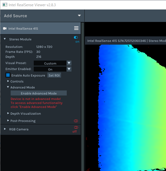
Once enabled, the Advanced Controls section (per depth sensor) exposes the following groups. Each numeric field also has an inline edit-mode toggle (pencil icon) to type an exact value instead of dragging its slider:
| Group | Fields |
|---|---|
| Depth Control | DS Second Peak Threshold, DS Neighbor Threshold, DS Median Threshold, Estimate Median Increment, Estimate Median Decrement, Score Minimum Threshold, Score Maximum Threshold, DS LR Threshold, Texture Count Threshold, Texture Difference Threshold |
| Rsm | RSM Bypass, Disparity Difference Threshold, SLO RAU Difference Threshold, Remove Threshold |
| Rau Support Vector Control | Min West, Min East, Min WE Sum, Min North, Min South, Min NS Sum, U Shrink, V Shrink |
| Color Control | Disable SAD Color, Disable RAU Color, Disable SLO Right Color, Disable SLO Left Color, Disable SAD Normalize |
| Rau Color Thresholds Control | Diff Threshold Red, Diff Threshold Green, Diff Threshold Blue |
| SLO Color Thresholds Control | Diff Threshold Red, Diff Threshold Green, Diff Threshold Blue |
| SLO Penalty Control | K1 Penalty, K2 Penalty, K1 Penalty Mod1, K1 Penalty Mod2, K2 Penalty Mod1, K2 Penalty Mod2 |
| HDAD | Ignore SAD, AD Lambda, Census Lambda |
| Color Correction | Color Correction 1 – 12 |
| Depth Table | Depth Units, Depth Clamp Min, Depth Clamp Max, Disparity Mode, Disparity Shift |
| AE Control | Mean Intensity Set Point (hidden on D457 and D500-family devices) |
| Census Enable Reg | u-Diameter, v-Diameter |
| Disparity Modulation | A Factor |
For programmatic access to these same controls (the Advanced Mode C/C++ API), see doc/rs400/rs400_advanced_mode.md.
Reached from the device's "More" menu.
D400 devices:
- On-Chip Calibration
- Focal Length Calibration (disabled on D421)
- Tare Calibration
- UV-Mapping Calibration — improves UV-mapping accuracy against a specific calibration target.
- Calibration Data
- Recover Logs from Flash
D500 devices:
- On-Chip Calibration
- Dry Run On-Chip Calibration
- Focal Length Calibration
- Tare Calibration
- Calibration Data
If a device supports no auto-calibration at all, the menu shows greyed-out On-Chip Calibration and Tare Calibration entries.
Each flow opens its own wizard window with a Calibrate (or flow-specific) button to start, a More Options... / Less Options... expander revealing tuning parameters (number of frames to average, max iteration steps, subpixel accuracy level), target-size fields (width/height in millimeters, where applicable), a health-check readout once calibration completes, and Retry / Abort controls, plus Commit / Discard buttons on D500 to apply or reject the new calibration.
In the default 2D (tiled) view, each stream tile has its own small toolbar:
| Icon | Behavior |
|---|---|
| Graph | Opens/closes a graph view of the stream's values over time. |
| List | Shows/hides frame metadata. |
| Crosshair/grid | Shows/hides a crosshair overlay. |
| Ruler (depth streams) | Shows/hides a color-map ruler/legend. |
| Polygon | Shows/hides Safety Zones overlay. |
| Play/Pause | Pauses/resumes this specific sensor. |
| Camera | Saves a snapshot of the current frame to an image file. |
| Info circle | Shows/hides a stream info overlay. |
| Maximize/restore | Maximizes this tile to full-screen, or restores the tiled layout. |
| ✕ | Stops this sensor. |
The 3D view's header bar has the following controls:
| Button | Behavior |
|---|---|
| Resume / Pause | Pauses or resumes all streams. |
| Reset | Resets the 3D camera to its initial viewpoint. |
| Lock / Unlock | Locks or unlocks the point cloud and texture data together. |
| Source | Opens a dropdown to pick which depth stream feeds the point cloud. |
| Texture | Opens a dropdown to pick which stream textures the point cloud. |
| Shading | Opens a dropdown: Raw Point-Cloud, Flat-Shaded Mesh, or With Diffuse Lighting (the last two require GLSL rendering, see Settings dialog). |
| Measure | Toggles the Measurement Tool on/off (requires GLSL rendering and processing to be enabled). |
| Export | Opens the export dialog (see below); disabled if there's no point-cloud data yet. |
| Point Size | Only shown for Labeled Point Cloud data: Small / Medium / Large. |
| S. Zones | Shows/hides the Safety Zones overlay in the 3D view. |
Export dialog — currently supports exporting to PLY, with:
- Meshing checkbox — connects each group of 3 adjacent points into faces.
- Normals checkbox — calculates vertex normals and adds them to the PLY (requires Meshing).
- Textual / Binary encoding radio buttons.
-
Export (opens a save dialog and writes the
.plyfile) / Cancel.
Mouse & keyboard camera controls in the 3D view:
- Left-drag — rotate the view.
- Middle-drag, right-drag, or Ctrl + left-drag — pan the view.
- Mouse wheel — zoom in/out.
- W / A / S / D — dolly the camera forward / left / back / right.
- R — reset the camera to its default pose.
Enabled/disabled via the Measure button in the 3D viewer toolbar (requires GLSL rendering and processing). While enabled, click on the point cloud surface to place points:
- Clicking two points measures the distance between them.
- Holding Shift while clicking additional points extends the chain into a polygon, so the tool reports an enclosed area instead of a single distance.
Distances and areas are shown as floating labels and connecting rulers in the unit system selected under Settings → General → Units of Measurement.
Recording: use the per-device Record button (see Device header icons). Depending on Settings → Playback & Record, the file is either auto-named and saved to the configured default recording folder, or you're prompted with a save dialog (.bag, or .db3 in ROS2-bag builds). The Record button's tooltip explains why it's disabled if applicable (e.g. "Start streaming to enable recording").
Playback: when the active "device" is a loaded recording, its panel shows playback transport controls instead of streaming controls:
- Stop
- Play / Pause
- Step Forward (disabled for formats that don't support stepping)
- Repeat — toggles looping playback.
- Speed combo — x0.25, x0.5, x1, x1.5, x2.
- Seek bar — a draggable progress slider with elapsed/total time.
| Key | Effect |
|---|---|
| F8 | Toggle fullscreen. |
| W / A / S / D | Dolly the 3D camera forward / left / back / right. |
| R | Reset the 3D camera to its default pose. |
| Space | Pause/resume all streaming while hovering the viewport. |
| Ctrl + left-drag (mouse) | Pan the 3D view (alternate to middle/right-drag). |
| Shift (held while clicking, in the Measurement Tool) | Chain more than 2 points to measure an area instead of a distance. |