3.Implementation
Table shows the APB pins used to interface to external devices.
| Signals | Source | Description |
|---|---|---|
| pclk | Clock source | Clock. The rising edge of PCLK times all transferon the APB. |
| preset_n | System bus equivalent | Reset. The APB reset signal is active low. This signal is normally connected directly to the system bus reset signal |
| paddr | APB bridge | Address. This is the APB address bus.It can be up to 32 bits wide and is a data access or an instruction access. |
| pprot | APB bridge | Protection type. This signal indicates the normal, privileged, or secure protection level of the transaction and whether the transaction is a data access or an instruction access. |
| pselx | APB bridge | Select. The APB bridge unit generates this signal to each peripheral bus slave. It indicates that the slave device is selected and that a data transfer is required. There is a pselx signal for each slave. |
| penable | APB bridge | Enable. This signal indicates the second and subsequent cycle of an APB transfer. |
| pwrite | APB bridge | Direction. This signal indicates an APB write access when HIGH and an APB read access when LOW. |
| pwdata | APB bridge | Write data. This bus is driven by the peripheralbus bridge unit during the write cycle when pwrite is HIGH. This bus can be up to 32 bits wide. |
| pstrb | APB bridge | Write strobes. This signal indicates when byte lanes to update during a write transfer. There is one write strobe for each eight bits of the write data bus. Therefore, pstrb[n] corresponds to pwdata[(8n+7):(8n)]. Write strobes must not be active during a read transfer. |
| pready | Slave interface | Ready. The Slave uses this signal to extend an APB transfer. prdata Slave interface Read Data.The selected slave drives this bus during read cycles when pwrite is LOW. This bus can be up to 32-bits wide. |
| pslverr | Slave interface | This signal indicates a transfer failure. APB peripherals are not required to support the pslverr pin. This is true for both existing and new APB peripheral designs. Where a peripheral does not include this PIN then the appropriate input to the APB bridge is tied LOW. |
Hdl top is synthesizable, where generation of the clock and reset is done. Instantiation of the apb interface handle, master agent bfm handle and slave agent bfm handle is done as shown in Figure .
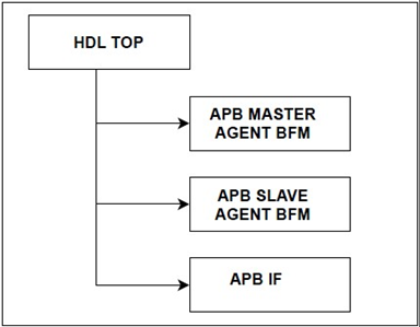
Fig. 3.1-HDL Top
Importing the global packages Passing Signals: pclk, preset_n Declaration of signals: paddr, pwrite, pwdata, pstrb, penable, pready, prdata, pslverr, pprot are declared as logic type.
Instantiates the below two interfaces here
a) apb master driver bfm and
b) apb master monitor bfm.
Instantiates the apb master assertions and binds it with the apb master monitor bfm handle and maps the signals of apb master assertions with the apb interface signals. The apb interface signals are passed to the apb master driver and monitor bfm in instantiations.
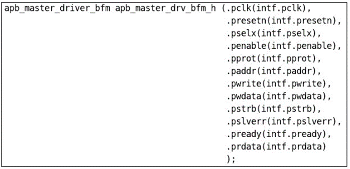
Fig.3.2- APB driver bfm instantiation in apb master agent bfm code snippet
Above Fig. are the code snippets of instantiations of apb master driver and monitor bfm
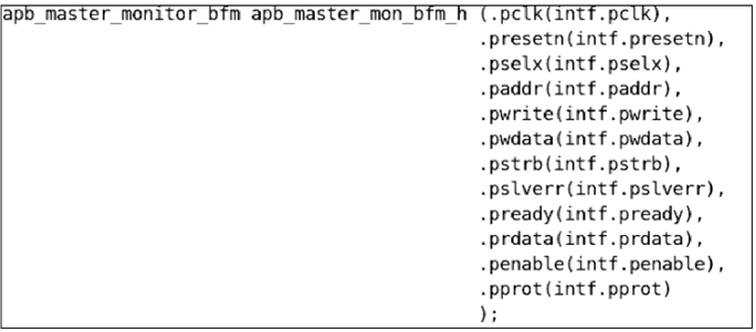
Fig.3.3- APB monitor bfm instantiation in apb master agent bfm code snippet
Apb master driver bfm is an interface where it will get the signals from the apb interface. It has a method drive_to_bfm which will be called by the apb master driver proxy which drives the paddr and pwdata data to the apb interface. fig.3.2 gives the reference of the instantiation of apb master driver bfm.
Apb master monitor bfm is an interface where it will get the signals from the apb interface. It has a method sample_data which will be called by the apb master monitor proxy which samples the paddr, pselx, pwdata and apb_avip_architectural_documentprdata data from the apb interface. After sampling the data, the apb master monitor bfm interface sends the data to the apb master monitor proxy using the output port of sample_data task. Fig.3.3 gives the reference of the instantiation of apb master monitor bfm.
Instantiates the below two interfaces here
1.apb slave driver bfm and
2.apb slave monitor bfm.
Instantiates the apb slave assertions and binds it with the apb slave monitor bfm handle and maps the signals of apb slave assertions with the apb interface signals. The apb interface signals are passed to the apb slave driver and monitor bfm in instantiations
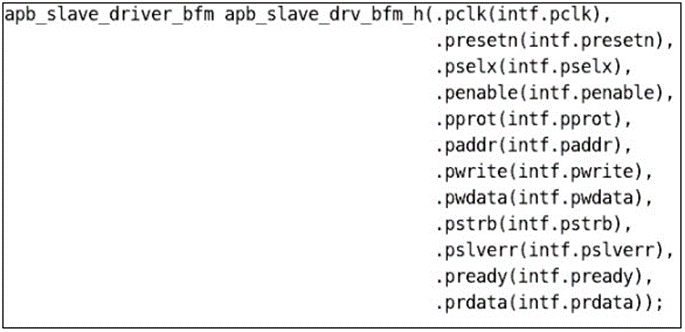
Fig.3.4- APB slave driver bfm instantiation in apb slave agent bfm code snippet
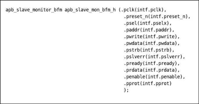
Fig.3.5 APB slave monitor bfm instantiation in apb slave agent bfm code snippet
APB slave driver bfm is an interface where it will get the signals from the apb interface. It has a method drive_to_bfm which will be called by the apb slave driver proxy which drives the prdata data to the apb interface. fig.3.4 gives the reference for the instantiation of apb slave driver bfm.
APB slave monitor bfm is an interface where it will get the signals from the apb interface. It has a method sample_data which will be called by the apb slave monitor proxy which samples the pwdata and prdata from the apb interface. After sampling the data, the apb slave monitor bfm interface sends the data to the apb slave monitor proxy using the output port of sample_data task. fig.3.5 gives the reference for the instantiation of apb slave monitor bfm.
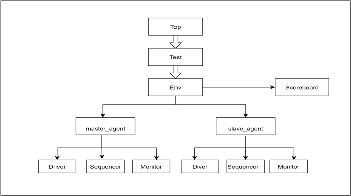
Fig.3.6- HVL Top
In top test is running by using the run_test(“test_name”) method, which will start the whole tb components.
Environment has the below components a. apb_scoreboard b. apb_virtual_sequencer c. apb_master_agent d. apb_slave_agent In the build phase, env_cfg handle will be called and create the memory for the above declared components. In the connect phase, the apb_master_monitor_proxy is connected to apb_scoreboard and apb_slave_monitor_proxy to apb_scoreboard using analysis port and analysis fifo as shown in fig
A scoreboard is a verification component that contains checkers and verifies the functionality of a design. The scoreboard is implemented by extending uvm_ scoreboard.
The purpose of the scoreboard in the APB-AVIP project is to
1.Compare the PWDATA, PADDR, PWRITE and
PRDATA data from the slave and master
2.Keep track of pass and failure rates identified in the comparison process
3.Report comparison success/failures result at the end of the simulation
The scoreboard consists of two analysis fifo’s which receive the packets from the analysis port of the monitor class. fig. 3.7 shows the connection between the analysis port and analysis fifo.
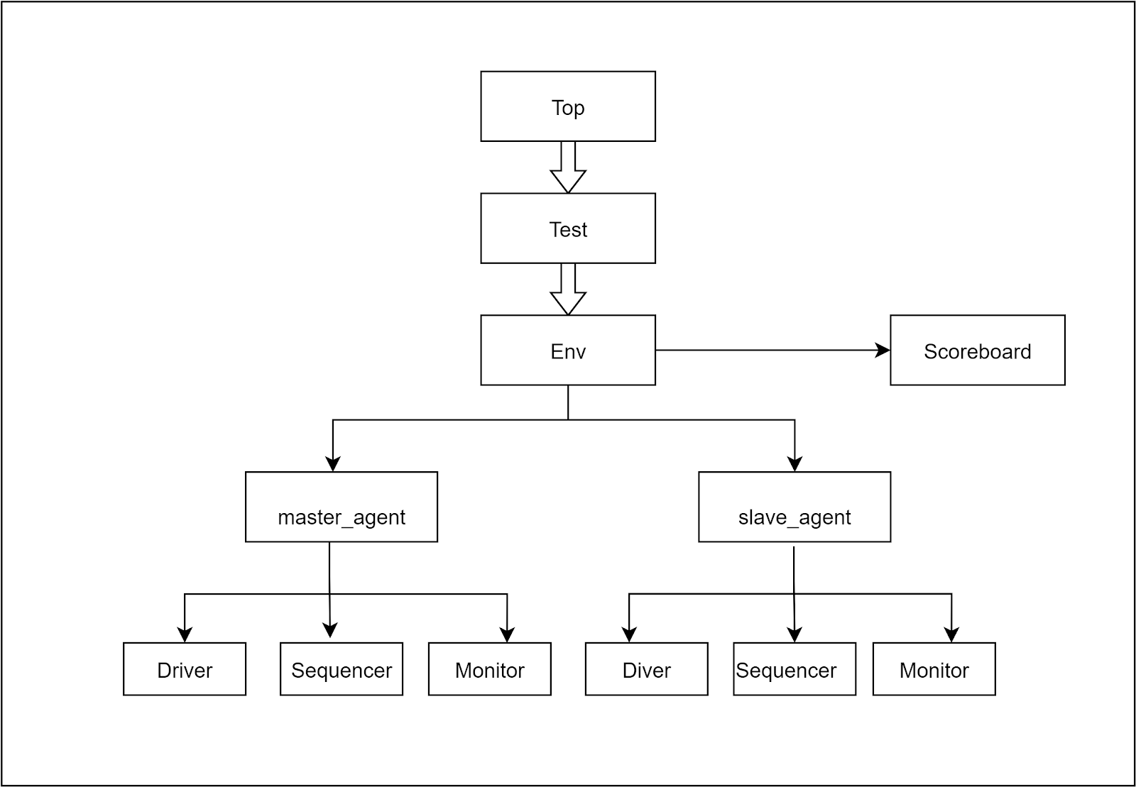
Fig.3.7- Connection of the analysis ports of the monitor to the scoreboard analysis fifo
In the monitor proxy class of master and slave, two analysis ports are declared. Fig 3.8 shows the declaration of master analysis port and slave analysis port in the master monitor proxy and slave monitor proxy.

Fig.3.8- Shows the declaration of slave and master analysis port in the slave and master monitor proxy
In the scoreboard, two analysis fifo’s are declared. Fig 3.9 shows the declaration of master analysis fiifo and slave analysis fifo in the scoreboard.
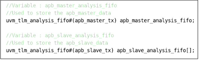
Fig.3.9- shows the declaration of master and slave analysis fifo in the scoreboard
In the constructor, create objects for the two declared analysis fifo’s.
Fig 3.10 shows the creation of the master and slave analysis port.

Fig.3.11- shows the creation of the master and slave analysis port
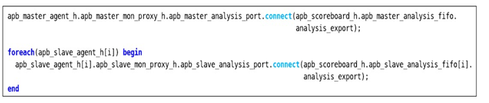
In connect phase of the environment class, the analysis port of both master and slave monitor proxy class is connected to the analysis export of the master and slave fifo in the scoreboard. shows the connection made between the monitor analysis port and the scoreboard fifo’s in the connect phase of the env class.
Fig Connection done between the analysis port and analysis fifo export in the env class
In the run phase of the scoreboard, the get() method is used to get the data packet from the monitor write() method. Fig 3.12 shows the use of the get() method to get the transaction from the monitor analysis port.
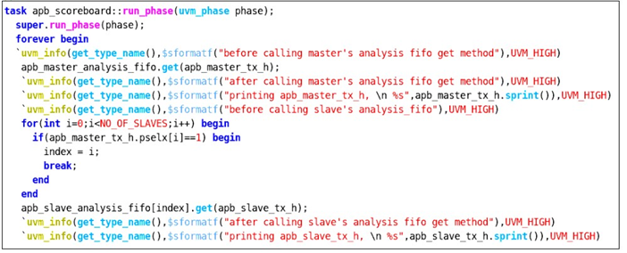
Fig 3.12 Use of get method to get the packet from monitor analysis port
The Comparison of the paddr, pwrite, pwdata and prdata from the master monitor and slave monitor is done in the run phase. Fig 3.13 shows the comparison of the master pwdata with slave pwdata.
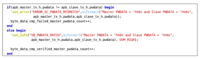
Fig 3.13 The comparison of the master pwdata with slave pwdata
Similarly, the comparison is done for the signals as well. Fig 3.14 explains the flow chart of the run phase in the scoreboard.
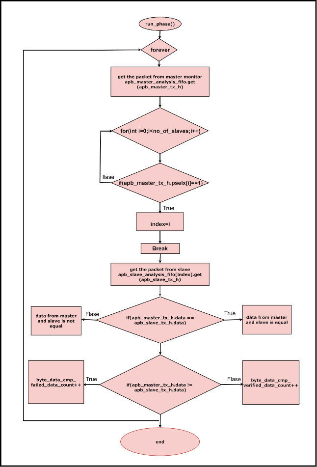
Fig 3.14 Flow chart of the scoreboard run phase
In the run phase, inside the forever loop, the scoreboard master analysis fifo gets the transaction from the master monitor analysis port using the get() method. Whenever the packet is received the transaction counter i.e, master_tx_count will be incremented.
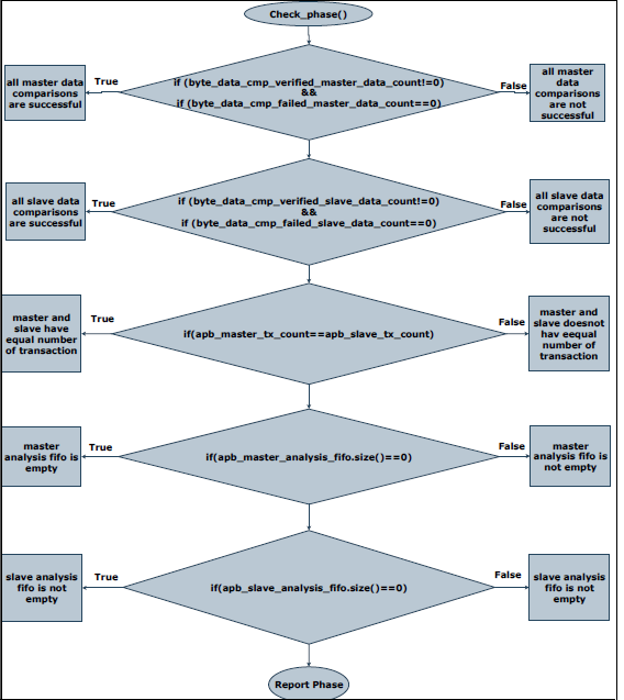
Fig 3.15 Flow chart of the scoreboard report phase
In virtual sequencer , declaring the handles for environment_configuration, master_sequencer and slave_sequencer. In the build phase, environment_configuration and creating the memory for master_sequencer and slave_sequencer.
APB master agent component is a class extending from uvm_agent. It gets the apb master agent config handle and based on that we will create and connect the components. It creates the apb master sequencer and apb master driver only if the apb master agent is active which will depend on the value of is_active variable declared in the apb master agent configuration file. The apb master coverage is created in build_phase if the has_ coverage variable is 1 which is declared in the apb master agent configuration file. Please refer to figure 3.16 for the apb master agent build_phase code snippet.
APB master agent build phase has creation of,
a. apb master sequencer
b. apb master driver proxy
c. apb master monitor proxy
d. apb master coverage components.
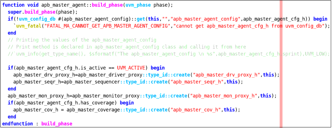
Fig 3.16 APB master agent build phase code snippet
APB master agent configuration handles declared in the above created components will be mapped here in the connect phase. The apb master driver proxy and apb master sequencer are connected using TLM ports if the apb master agent is active. The apb master coverage’s analysis_export will be connected to apb master monitor proxy’s master_analysis_port in connect_phase.
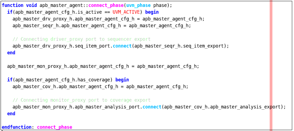
Fig 3.17 APB master agent connect phase code snippet
APB master sequencer component is a parameterised class of type apb master transaction, extending uvm_sequencer. APB sequencer sends the data from the apb master sequences to the apb driver proxy.
APB master driver proxy component is a parameterised class of type apb master transaction, extending uvm_driver. It gets the apb master agent config handle and based on the configurations we will drive and sample the paddr, pselx, pwdata and prdata signals respectively. It gets the master transaction into the apb driver proxy using get_next_item() method.
As the apb driver bfm interface cannot access the class based apb master transaction data, so we have to convert that into struct data type. Similarly, it converts the apb master configuration values into struct data type. APB master driver proxy will call the converter class to convert the master transaction packet and master configuration packet into struct data packet and struct configuration packet respectively (declared in apb global package) and then will pass it to apb master driver bfm using drive_to_bfm method declared in apb master driver bfm. The drive to bfm method starts the drive_to_bfm (data_packet, configuration packet) which is declared in apb driver bfm.
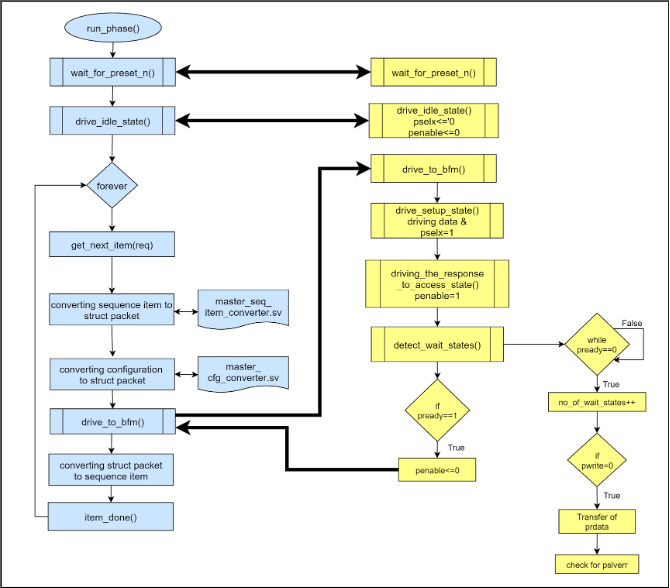
Fig 3.18 Flowchart of communication between apb master driver proxy and apb master driver bfm
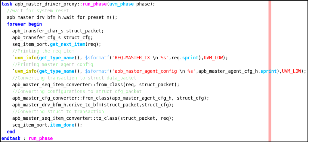
Fig 3.19 run phase of apb master driver proxy code snippet
APB master monitor proxy component is a class extending uvm_monitor. It gets the apb master agent config handle and based on the configurations we will sample the pwdata and prdata signals. It declares and creates the apb master analysis port to send the sampled data.
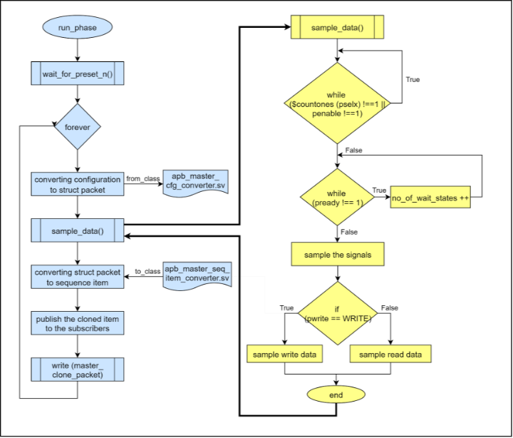
Fig 3.20 Flowchart of apb master monitor proxy and apb master monitor bfm communication
APB slave agent component is a class extending uvm_agent. It gets the apb slave agent configuration and based on that we will create and connect the components. It creates the apb slave sequencer and apb slave driver only if the apb slave agent is active which will depend on the value of is_active variable declared in the apb slave agent configuration file. The apb slave coverage is created in build_phase if has_covergae variable is 1 which is declared in the apb slave agent configuration file.
APB slave agent build phase has creation of,
a.apb slave sequencer
b.apb slave driver proxy
c.apb slave monitor proxy
d.apb slave coverage components.
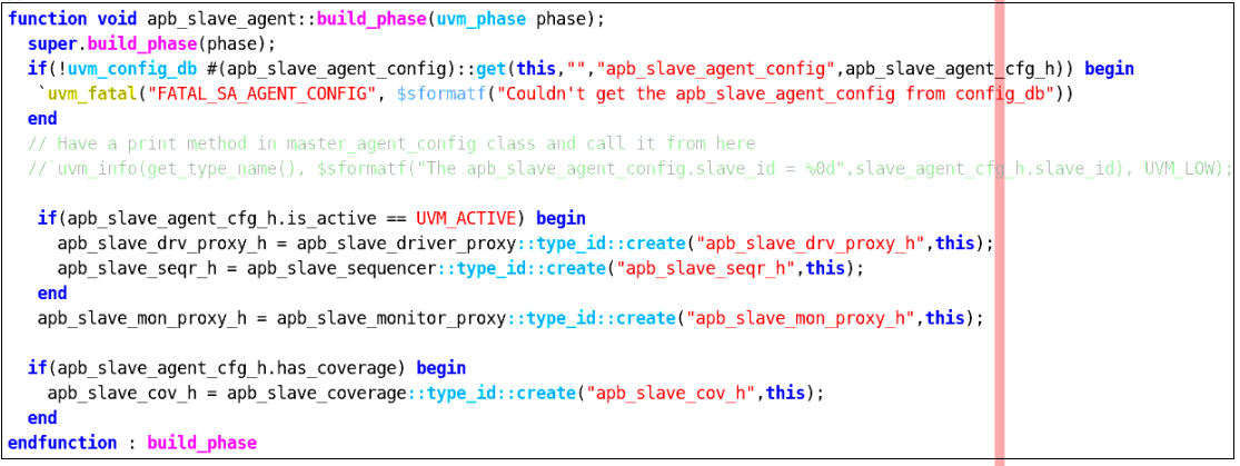
Fig 3.21 APB slave agent build phase code snippet
APB slave sequencer component is a parameterised class of type apb slave transaction, extending uvm_sequencer. APB sequencer sends the data from the apb slave sequences to the apb driver proxy.
APB slave driver proxy component is a parameterised class of type apb slave transaction, extending uvm_driver. It gets the apb slave agent config handle and based on the configurations we will drive and sample the pwdata and prdata signals respectively. It gets the slave transaction into the apb driver proxy using get_next_item() method.
As the apb driver bfm interface cannot access the class based apb slave transaction data, so we have to convert that into struct data type. Similarly, it converts the apb slave configuration values into struct data type. APB slave driver proxy will call the converter class to convert the slave transaction packet and slave configuration packet into struct data packet and struct configuration packet respectively(declared in apb global package) and then will pass it to apb slave driver bfm using drive to bfm method declared in apb slave driver bfm. The drive to bfm method starts the drive_to_bfm (data_packet, configuration packet) which is declared in apb driver bfm.
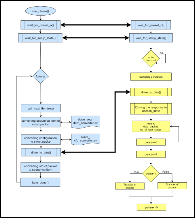
Fig 3.23 Flowchart of apb slave driver bfm and slave driver proxy communication
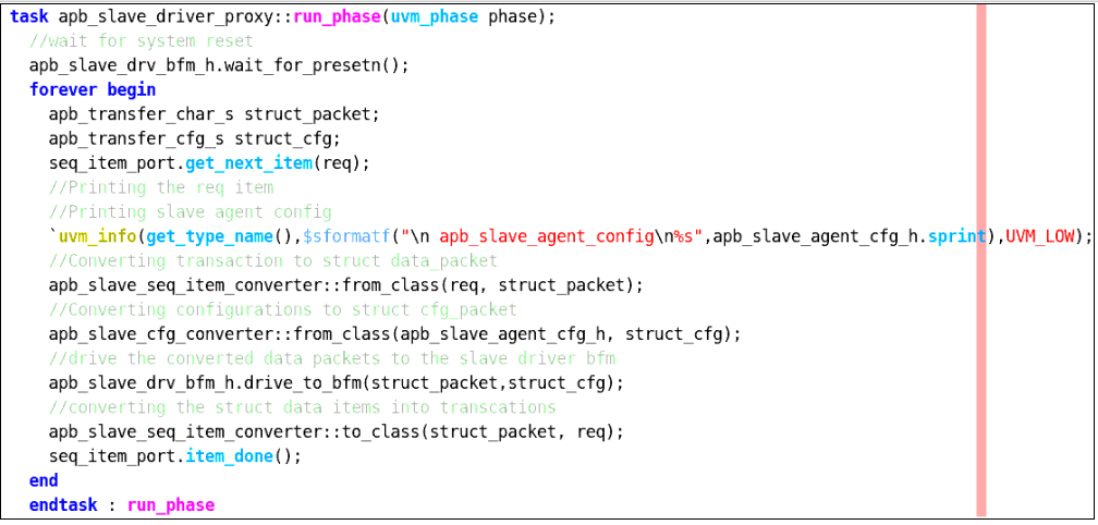
Fig 3.24 APB slave driver proxy run phase code snippet
APB slave monitor proxy component is a class extending uvm_monitor. It gets the apb slave agent config handle and based on the configurations we will sample the pwdata and prdata signals. It declares and creates the apb slave analysis port to send the sampled data. The apb slave monitor proxy will get the sampled data from apb master monitor bfm as shown in figure 3.25.
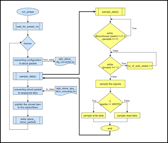
Fig 3.25 Flowchart of apb slave monitor bfm and slave monitor proxy communication
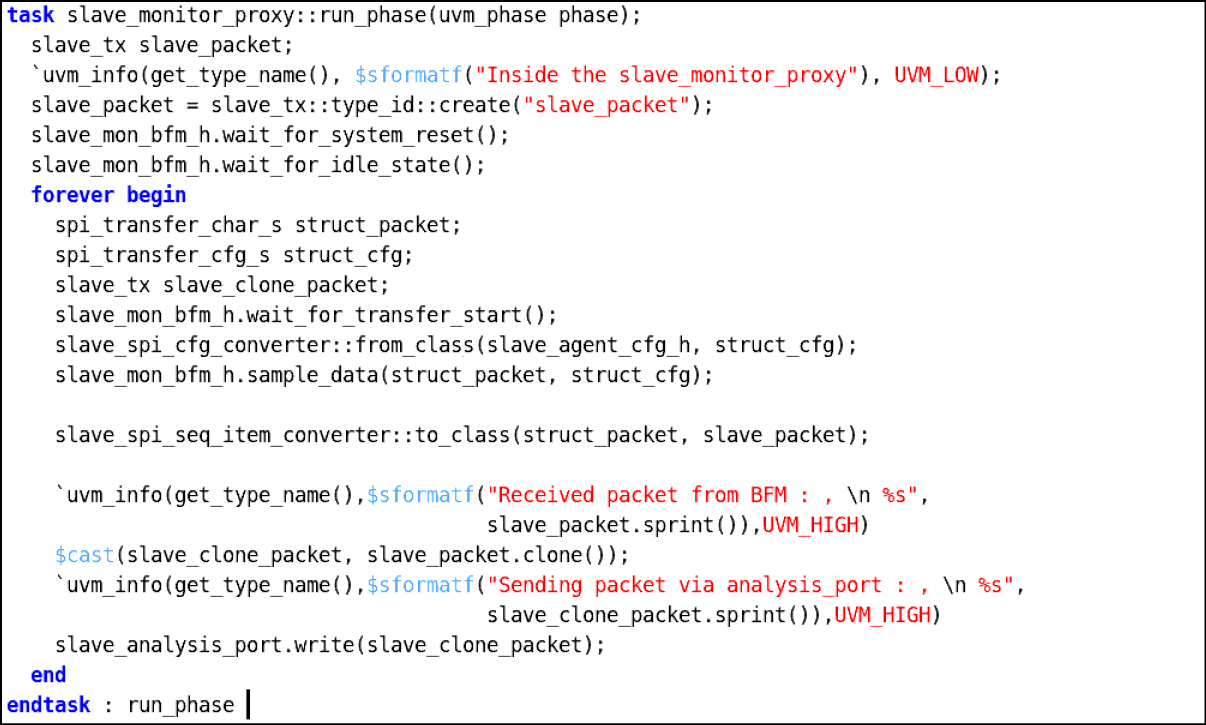
Fig 3.26 run phase of apb slave monitor proxy code snippet
There are predefined UVM verbosity settings built into UVM (and OVM). These settings are included in the UVM src/uvm_object_globals.svh file and the settings are part of the enumerated uvm_verbosity type definition. The settings actually have integer values that increment by 100 as shown below table
Table 3.2 UVM verbosity Priorities
| Verbosity | Default Value |
|---|---|
| UVM_NONE | 0(Highest Priority) |
| UVM_LOW | 100 |
| UVM_MEDIUM | 200 |
| UVM_HIGH | 300 |
| UVM_FULL | 400 |
| UVM_DEBUG | 500(Lowest Priority) |
Table 3.3 Descriptions of each Verbosity level
| Verbosity | Description |
|---|---|
| UVM_NONE | UVM_NONE is level 0 and should be used to reduce report verbosity to a bare minimum of vital simulation regression suite messages. |
| UVM_LOW | UVM_LOW is level 100 and should be used to reduce report verbosity and only shows important messages |
| UVM_MEDIUM | UVM_MEDIUM is level 200 and should be used as the default $display command. If the verbosity isn’t selected then, these messages will print by default as UVM_MEDIUM. This verbosity setting should not be used for any debugging messages or for standard test-passing messages. |
| UVM_HIGH | UVM_HIGH is level 300 and should be used to increase report verbosity by showing both failing and passing transaction information, but does not show annoying UVM phase status information after it has been established that the UVM phases are working properly |
| UVM_FULL | UVM_FULL is level 400 and should be used to increase report verbosity by showing UVM phase status information as well as both failing and passing transaction information. |