Pico Debug Build Notes
pico_debug is designed for hand-soldered construction. I soldered mine up in a few steps.
- pico_debug PCB
- 2x Raspberry Pi Pico (headerless version)
- 3x 6mm Tactile Switch (optionally, choose different colours for each function)
- 1x 220ohm resistor
- 1x 3mm LED, any colour
- Optional 3x2 header
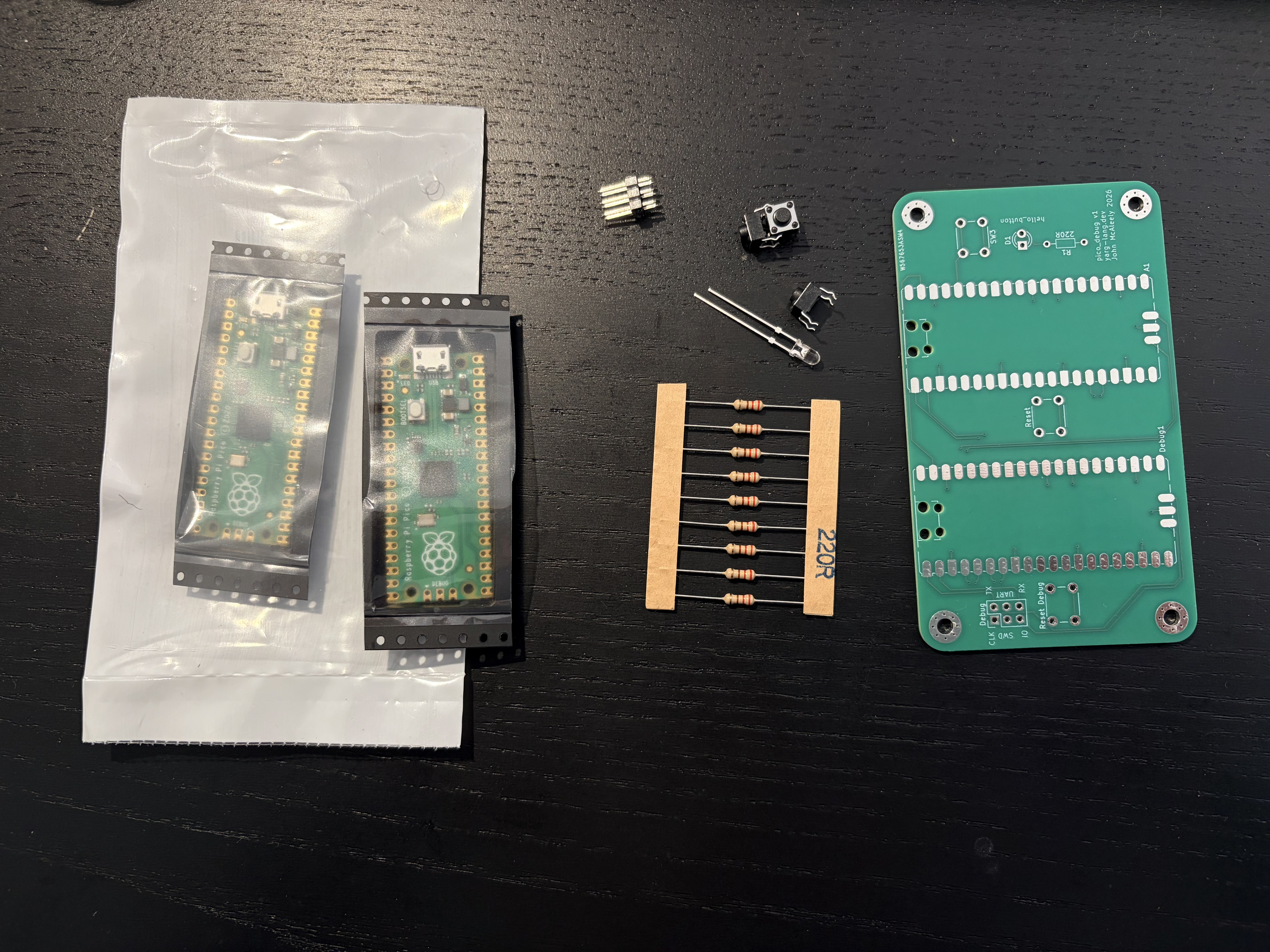
Note: only one of the resistors is needed!
-
I soldered in approximate height order, starting with the two Picos. I tested each after soldering, by plugging its USB into a host PC, and checking it presented the RPI-RP2 USB drive.
-
After adding the resistor, I then added each button. The two reset buttons can be tested with the Pico's again connected via USB, and seeing that the drive is removed and restarts when the button is pressed.
-
I added the LED, and if I fitted it, the header.
-
Any Yarg image with hello_led.ya can be used to test the LED comes on when the button is pressed. I used 0.4.0.
-
I flashed the debug Pico with the latest debug probe firmware, and confirmed it presented a USB serial port to the host PC on boot. This will show the
yarg>prompt if you've flashed Yarg on the target Pico.
- Optionally, you can fit the 2x3 header, and test debugging the debug pico. You will need a debug probe to do that. I have found no practical use for this.
Your board will look something like this:
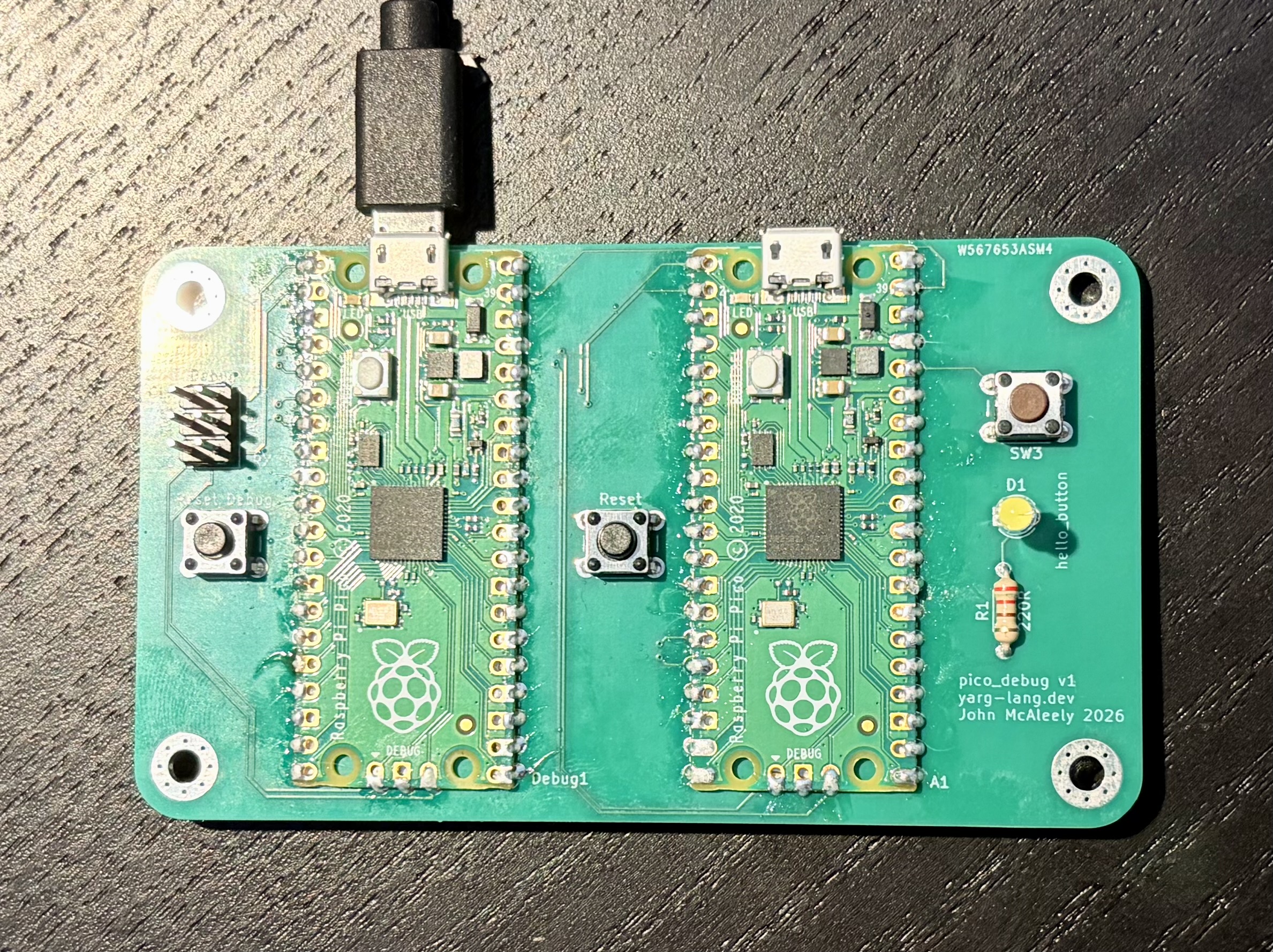
This is complete, and ready for use.