Pico Debug Usage Notes
pico-debug provides a Pico for development ('target Pico') which has UART 0 (on pins 1-3) and the SWD debug connection permanently wired to a second pico ('debug pico'). This second pico can be loaded with debug probe firmware from Raspberry Pi. This firmware will expose two USB connections: Serial and CMIS-DAP. Serial can be used with any suitable terminal emulator, and bi-directionally echos the UART0 output from the target pico. the CMIS-DAP connection can be used with OpenOCD and other debuggers to flash firmware, breakpoint, step etc the target Pico. VSCode's Pico plugin will use it without any configuration steps.
The serial connection from the debug pico has the advantage of remaining connected when the target pico is reset. Unlike the USB serial available on the target pico, this will provide UART 0 traffic from boot, without having to wait for Host-Pico USB negotiation.
Your board will look something like this (the labels have been revised on some versions):
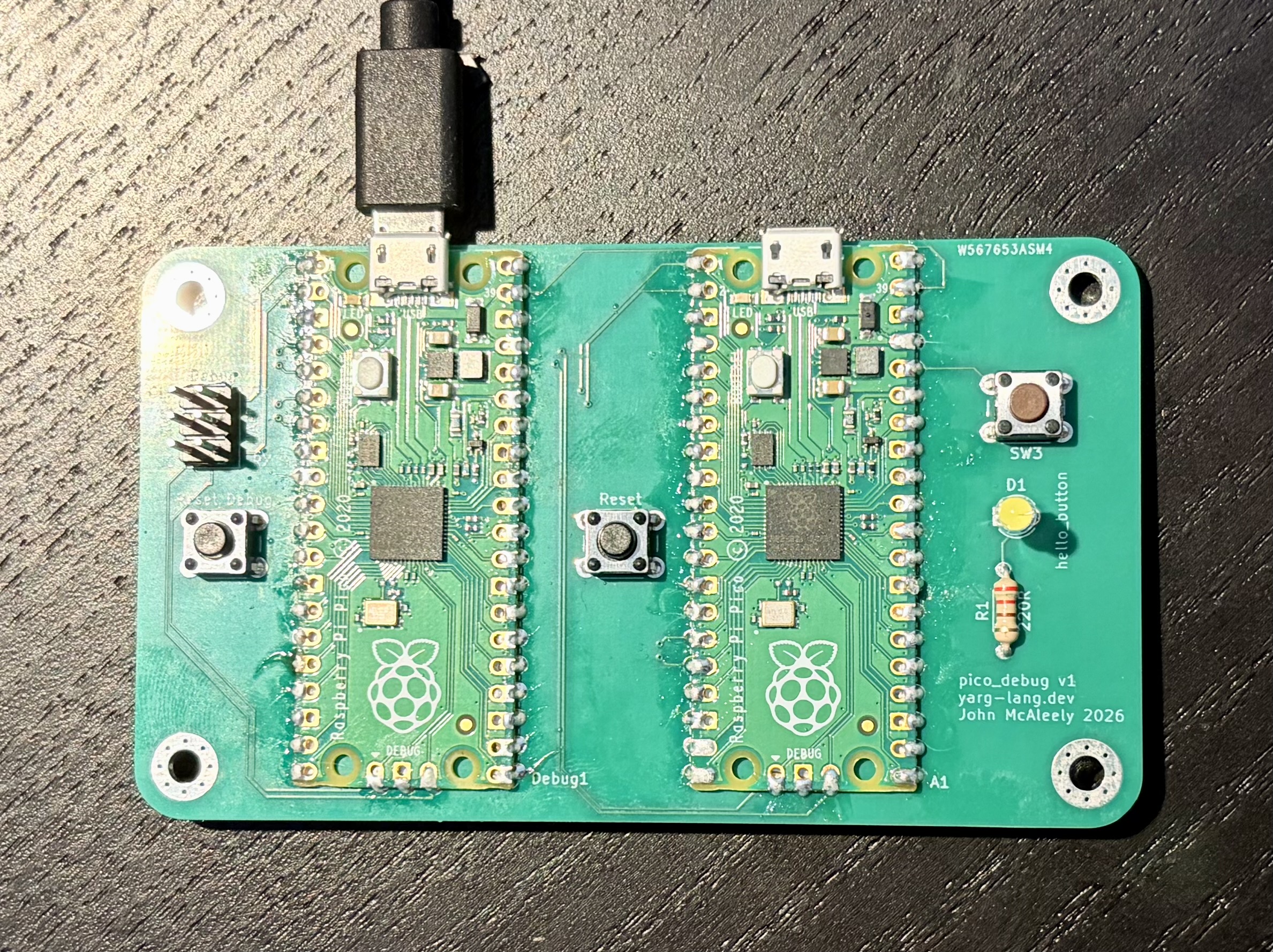
From left to right:
- The 3x2 header can be used to debug the debug pico if required. This is optional, and may not be populated
- Reset button for Debug Pico
- Debug Pico (note USB connector at the top)
- Reset button for Target Pico
- Target Pico (note USB connector at the top)
- hello_button circuit - switch attached to GPIO 11 (Pin 15), and LED+Resistor attached to GPIO 12 (Pin 16)
The picos can be used independently, and both may have their USB connection present to the same Host PC. It is reasonable to use the 'bootsel' and 'reset' buttons on the target pico to load firmware via the RPI-RP2 USB interface. However, the typical intended usage is to connect the debug pico USB to the host, and leave the target pico USB unconnected. This setup can be used via OpenOCD to flash and inspect the target Pico in a debugger.
The board can also be used with the debug pico unconnected, and only the target pico in use. In this case the debug pico is unpowered and not in use.
The circuit 'hello_button' is attached to the target pico. This connects a switch to GPIO 11, and an LED (plus resistor) to GPIO 12. Yarg's hardware test suite uses this to exercise externally trigered interrupts, but the circuit can be used for any purpose.