Assembly Guide
All pin numbers below are GPIO numbers and match src/main.cpp. The PN5180 and TFT use separate SPI buses.
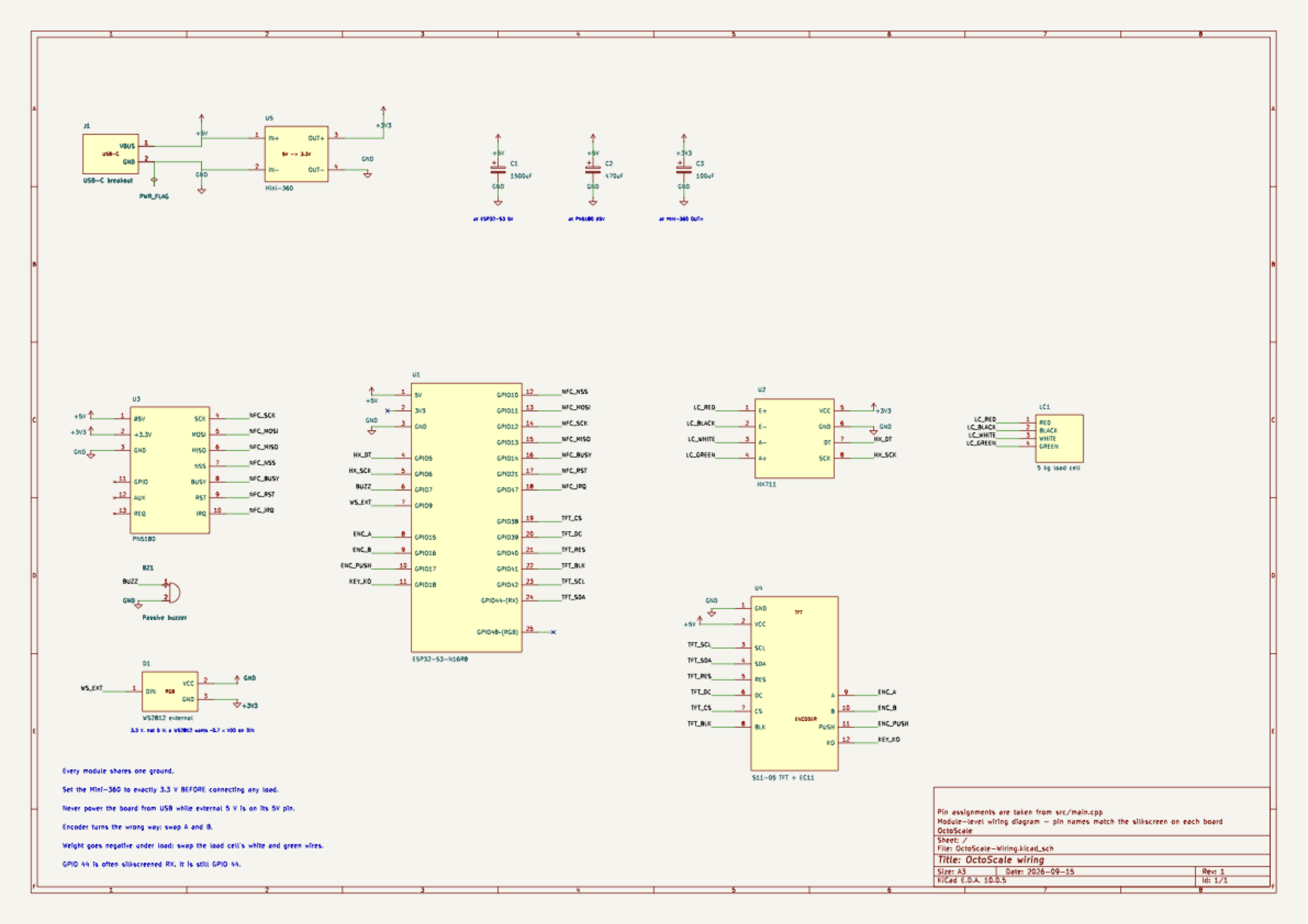
Every pin in the diagram carries the name printed on the module itself, so a symbol can be compared against the board in hand without translating part numbers. Signals are joined by net labels rather than long lines: NFC_SCK at the ESP32-S3 and NFC_SCK at the PN5180 are the same wire.
The KiCad source is in hardware/OctoScale-Wiring/ along with the module symbol library; the schematic passes ERC with no errors or warnings.
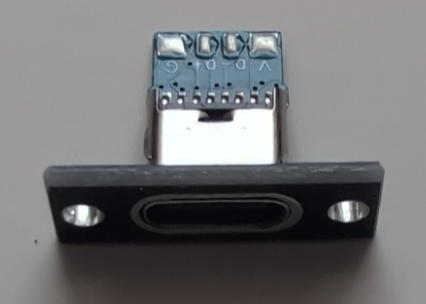
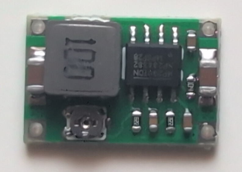
Power enters through the USB-C breakout. The 5 V rail powers the ESP32-S3, PN5180 RF section, and TFT. The Mini-360 converts 5 V to 3.3 V for the HX711, PN5180 logic, and external WS2812. Everything shares one ground.
Before connecting any load, feed the Mini-360 with 5 V and adjust OUT+ to exactly 3.3 V with a multimeter.
Then fit the three electrolytic capacitors. All mount with short leads directly at the points they buffer — a few centimetres of wire undoes most of the benefit — and all are polarised, so check the negative stripe before powering up.
| Capacitor | Across | Purpose |
|---|---|---|
| 470 uF | PN5180 #5V and GND
|
RF field current spikes |
| 1500 uF | ESP32-S3 5V and GND
|
WiFi transmit bursts |
| 100 uF | Mini-360 OUT+ and GND
|
the 3.3 V rail (HX711, PN5180 logic) |
The 470 uF one is what lets the PN5180 raise an RF field at all; without it the reader only detects tags sporadically. The other two keep the supply steady under load. Note the third sits at the converter output, not at the ESP32-S3's 3V3 pin — that pin is an output of the board's own regulator and feeds nothing here.
Warning
Never power the ESP32-S3 from USB while external 5 V is connected to its 5V/VBUS/VIN
pin. Disconnect the external supply for the first USB flash and any later recovery flash.
| Component | Pin | ESP32-S3 / rail |
|---|---|---|
Load cell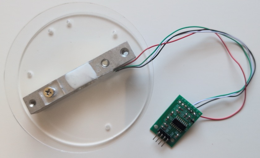
|
red / black / white / green | HX711 E+ / E- / A- / A+
|
| HX711
|
VCC, GND, DT, SCK
|
3.3 V, GND, GPIO 5, GPIO 6 |
PN5180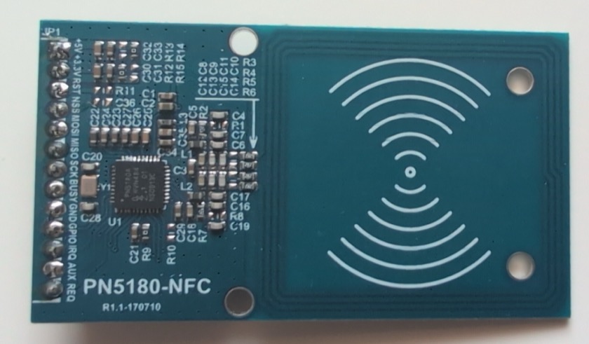
|
+5V, +3.3V, GND
|
5 V, 3.3 V, GND |
| PN5180
|
SCK, MOSI, MISO, NSS
|
GPIO 12, 11, 13, 10 |
| PN5180
|
BUSY, RST, IRQ
|
GPIO 14, 21, 47 |
TFT/encoder module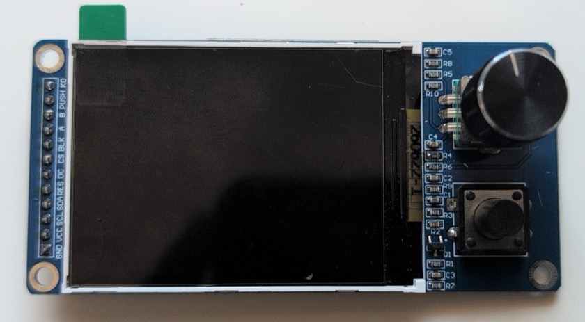
|
VCC, GND
|
5 V, GND |
| TFT
|
SCL, SDA, CS, DC, RES, BLK
|
GPIO 42, 44, 38, 39, 40, 41 |
| Encoder/buttons
|
A, B, PUSH, KO
|
GPIO 15, 16, 17, 18; other switch legs to GND |
Buzzer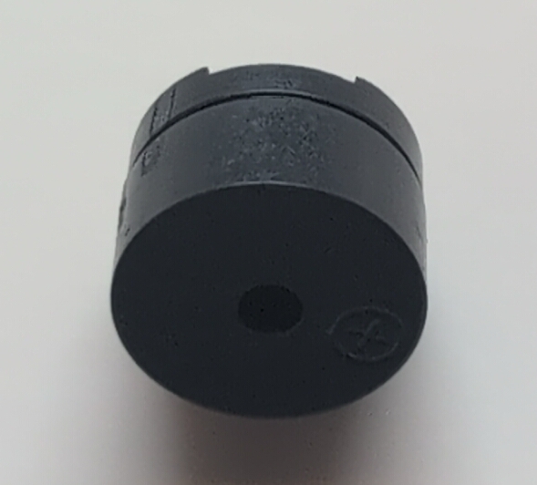
|
+, -
|
GPIO 7, GND |
External WS2812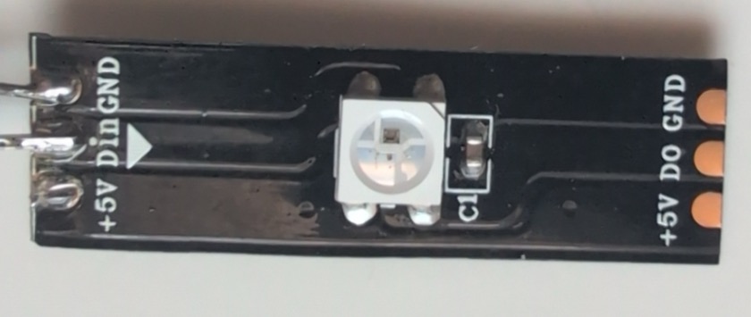
|
DIN, VCC, GND
|
GPIO 9, 3.3 V, GND |
GPIO 44 is often labelled RX; it is still GPIO 44. If encoder rotation is reversed, swap A and B. If weight becomes negative when loaded, swap the load-cell white and green wires. PN5180 GPIO, AUX, and REQ remain unconnected.
Mounting order is printed part, board, spacer, screw. Component names are embossed on the printed parts. The external WS2812 has no dedicated seat: solder its wires, test it, then glue it inside OctoScaleLit.stl behind the front opening. Use transparent filament for OctoScaleLEDCover.stl; sparse infill makes the diffuser cloudy.
Continue with the Setup Guide for build, flash, and first-time configuration.